EP2345558B1 - Dispositif de serrage pour un support de véhicule automobile ou pour un attelage - Google Patents
Dispositif de serrage pour un support de véhicule automobile ou pour un attelage Download PDFInfo
- Publication number
- EP2345558B1 EP2345558B1 EP11000188.0A EP11000188A EP2345558B1 EP 2345558 B1 EP2345558 B1 EP 2345558B1 EP 11000188 A EP11000188 A EP 11000188A EP 2345558 B1 EP2345558 B1 EP 2345558B1
- Authority
- EP
- European Patent Office
- Prior art keywords
- clamping
- clamping device
- tie rod
- thread section
- motor vehicle
- Prior art date
- Legal status (The legal status is an assumption and is not a legal conclusion. Google has not performed a legal analysis and makes no representation as to the accuracy of the status listed.)
- Active
Links
Images


Classifications
-
- B—PERFORMING OPERATIONS; TRANSPORTING
- B60—VEHICLES IN GENERAL
- B60R—VEHICLES, VEHICLE FITTINGS, OR VEHICLE PARTS, NOT OTHERWISE PROVIDED FOR
- B60R9/00—Supplementary fittings on vehicle exterior for carrying loads, e.g. luggage, sports gear or the like
- B60R9/08—Supplementary fittings on vehicle exterior for carrying loads, e.g. luggage, sports gear or the like specially adapted for sports gear
- B60R9/10—Supplementary fittings on vehicle exterior for carrying loads, e.g. luggage, sports gear or the like specially adapted for sports gear for cycles
-
- B—PERFORMING OPERATIONS; TRANSPORTING
- B60—VEHICLES IN GENERAL
- B60D—VEHICLE CONNECTIONS
- B60D1/00—Traction couplings; Hitches; Draw-gear; Towing devices
- B60D1/48—Traction couplings; Hitches; Draw-gear; Towing devices characterised by the mounting
- B60D1/52—Traction couplings; Hitches; Draw-gear; Towing devices characterised by the mounting removably mounted
-
- B—PERFORMING OPERATIONS; TRANSPORTING
- B60—VEHICLES IN GENERAL
- B60D—VEHICLE CONNECTIONS
- B60D1/00—Traction couplings; Hitches; Draw-gear; Towing devices
- B60D1/58—Auxiliary devices
- B60D1/62—Auxiliary devices involving supply lines, electric circuits or the like
- B60D1/64—Couplings or joints therefor
-
- B—PERFORMING OPERATIONS; TRANSPORTING
- B60—VEHICLES IN GENERAL
- B60R—VEHICLES, VEHICLE FITTINGS, OR VEHICLE PARTS, NOT OTHERWISE PROVIDED FOR
- B60R9/00—Supplementary fittings on vehicle exterior for carrying loads, e.g. luggage, sports gear or the like
- B60R9/06—Supplementary fittings on vehicle exterior for carrying loads, e.g. luggage, sports gear or the like at vehicle front or rear
Definitions
- the invention relates to a tensioning device for a motor vehicle carrier, in particular a bicycle carrier, or a trailer hitch, with a tie rod and a nut assembly screwed onto this, which is rosbetätigbar and having a tie rod threaded portion of the tie rod first intermeshing threaded portion to them along a Clamping axis axially to an abutment body towards a clamping position or away from this in a release position to be adjusted, wherein between the abutment body and the nut assembly, a spacer body is arranged.
- Such a tensioning device is provided for example in a motor vehicle carrier for transporting bicycles, which has a coupling holder for attachment to a trailer coupling of the motor vehicle.
- a pivotable bracket is provided which can be tensioned by means of the tensioning device in its position of use, in which it is substantially perpendicular to the base frame of the motor vehicle carrier. When not in use, you can flip the bar so that it takes up little space.
- a motor vehicle carrier is for example in DE 10 2008 012 689 described.
- DEU 9214916.2 discloses a tensioning device according to the preamble of claim 1. Clamping devices of this type are also used, for example, to attach bicycles to the aforementioned bracket.
- clamps are arranged on the bracket, for example, from which project spacer rods, which in turn hold clamps.
- the clamps can cling in their staple position or clamping position, for example, frame parts of the bike to be held.
- the spacer is for example a washer.
- the spacer body has a spacer body threaded portion opposite to the first rotational direction of rotation, with a coaxial with the first threaded portion second threaded portion of the nut assembly meshes, and that between the spacer body and a counter-support, in particular the abutment body, a counter to a rotary actuator effective frictional engagement and / or positive locking is present, so that the nut assembly simultaneously screwed in a rotary actuator on the spacer body and the tie rod and thereby changed a distance to the abutment body along the clamping axis.
- a basic idea of the invention is that in a rotational actuation of the nut assembly not only the movement stroke is used, which is present between the tie rod threaded portion and the first threaded portion of the nut assembly, but also the further movement stroke or the further axial adjustment by the Use spacer body threaded portion and the meshing with this second threaded portion of the nut assembly.
- the pitch of the threaded sections can be designed so that a certain self-locking exists.
- first and second threaded sections on one and the same component of the nut arrangement, for example a nut.
- An embodiment of the invention may also provide that the first threaded portion is disposed on a nut of the nut assembly, while the second threaded portion is provided on a screw body of the nut assembly, which is rotatably connected to the mother.
- the screw body for example, have a polygonal or other rotational resistance providing recording in which the mother is rotatably, but at least with a not too large rotational play, added. This makes it possible, for example, to use a conventional nut, for example with an M8 or M10 thread.
- the screw body can for example be formed by a sleeve body or having a sleeve body, which is penetrated by the tie rod. On the outer circumference of the sleeve body of the spacer body threaded portion is arranged.
- this sleeve body can also be integrally connected to the nut or be formed by a single component.
- the nut assembly has a radially outwardly projecting projection in front of the sleeve body, for example a collar, an annular projection or ring segment projections, which are provided for supporting on the abutment body.
- the support surface of the nut assembly is increased with respect to the abutment body.
- the first threaded portion of the nut assembly is formed for example by a right-hand thread or has a right-hand thread, while the second threaded portion forms a left-hand thread. It is understood that the reverse arrangement can be made.
- first and second threaded sections prefferably have different pitches, wherein equal pitches are preferred.
- first and the second threaded portion have different diameters. It is understood that a coaxial arrangement can be made, in which the two threaded portions are arranged one behind the other and can also have the same diameter in this embodiment. However, this is not shown in the embodiment according to the drawing.
- the spacer body and the abutment body expediently have mutually matching form-fitting contours, for example form-fitting receptacles and positive-fit projections, or also rotational stops.
- the rotation stops it should be noted that, for example, they can optionally enable a small amount of rotational play.
- a beating tensioning movement may be possible, so that, for example, a rotational play is utilized in the circumferential direction, as it were Get momentum to tension or release the tensioner.
- the aforementioned frictional engagement which is also possible between the spacer and the counter-support, in particular the abutment body, can be realized, for example, by a plastic coating, a rubber coating or the like. This can be provided on the spacer body and / or on the counter-stop, in particular on the abutment body.
- the abutment body expediently has, for the positive retention of the spacer body, at least one projection which projects radially with respect to the tie rod or a plurality of star-shaped projections for engagement in recesses of the spacer body.
- the spacer body has such projections or such a projection which engages correspondingly in a receptacle or in a plurality of receptacles of the abutment body.
- a combination of the aforementioned form-fitting contours is possible, in which the spacer body and the abutment body each have projections and respective receptacles.
- At least one form-fitting contour of the abutment body or the nut arrangement is expediently formed by a reinforcing rib.
- a reinforcing rib of the respective body for example, the abutment body or a component of the nut assembly is amplified, and the reinforcing function of this rib is additionally used to form-fit or a rotation stop between on the one hand the nut assembly and on the other hand, to provide the abutment body.
- abutment body is the preferred counterweight for the spacer body. But it is also possible that this is held against rotation by other components, for example, from another component of the motor vehicle carrier or the trailer coupling, with respect to the spacer body is rotatably, but can undergo axial displacement along the clamping axis, that is axially displaceable ,
- a support surface area of the nut arrangement for supporting on the abutment body is provided, for example, on a conical receptacle.
- the abutment body expediently has a conical projection region which engages in the abovementioned conical receptacle.
- the first threaded portion of the nut assembly is expediently an internally threaded portion, while the second threaded portion is an externally threaded portion. It is understood that the reverse configuration can also be made.
- the tie rod is expediently fixed in terms of rotation with respect to the abutment body.
- the abutment body itself firmly fixes the tie rod.
- the tie rod is fixed in rotation in the vicinity of the abutment body, so that the abutment body itself does not have to provide rotational strength.
- the tie rod expediently comprises a clamping bolt.
- the clamping bolt expediently has at its end remote from the tie rod threaded portion an abutment projection which is supported on the abutment body at least indirectly or directly.
- the abutment body is expediently penetrated by the tie rod. But it is also possible that the tie rod forms part of the abutment body. For example, the tie rod or the threaded portion of the same before the other area of the abutment body.
- the tensioning device comprises a tensioning clamp, wherein the tensioning clamp with the nut arrangement is adjustable between a clamping position and a release position.
- the clamp with the nut assembly is solved or clamped.
- the clamp can, for example, form the abutment body.
- a jaw of the clamp of the abutment body can be arranged between the clamping bracket and the abutment body.
- another component such as a spacer sleeve or the like, is arranged between the clamping bracket and the abutment body.
- the clamp is expediently designed as a clamp.
- the clamping clip expediently has a pivot bearing for a component to be clamped, which is received by the clamping clip.
- the component is rotatable relative to the clamping bracket in the release position of the clamping device, while in the clamping position, a rotational resistance is present.
- the pivot bearing can be adjusted so to speak between a rotational fixing position and a release position by means of the clamping device.
- the rotary bearing has a plug-in receptacle for the component to be clamped.
- a plug-in receptacle for the component to be clamped.
- the exciting part is, for example, a rod or a bracket of a motor vehicle carrier.
- the bracket is for example U-shaped.
- the bracket can be adjusted between a use position in which it protrudes in front of a frame of the motor vehicle carrier, and a rest position.
- the clamping device sets the bracket at least in the position of use when it is in its cocked position.
- a handle body is suitably rotatably connected to the mother. It is also possible that the nut is designed as a handle body.
- the handle body for example, have a screw extension, which penetrates into the spacer body. But it is also possible that, conversely, the spacer body penetrates into the screw extension.
- the handle body has a knob.
- the handle body may also be configured as a handwheel.
- a motor vehicle carrier e.g. a rear carrier or a bicycle carrier, at least one of the tensioning devices according to the invention.
- the motor vehicle carrier can be configured, for example, as a drawer which can be pulled out of a rear of the motor vehicle. But it is also possible that the motor vehicle carrier has a holder for attachment to the motor vehicle, e.g. a coupling bracket for attaching a trailer hitch.
- the invention may also find application in roof rack systems or tailgate carrier systems that require frequent loosening and clamping.
- an application field of the invention is a trailer coupling, for example an actuating device with which the trailer coupling can be locked or unlocked.
- FIG. 1 illustrated motor vehicle carrier 10 has a base frame 11, in which protrude from a cross member 12, two side members 13, so that a total of a U-shaped configuration is formed.
- a pivot frame 14 is pivotally mounted, the two adjacent, advantageously parallel to, the longitudinal members 13 extending pivot carrier 15, at the free ends 16, a bracket 17 is pivotally mounted by means of pivot bearings 18.
- the pivot bearings 18 make it possible to pivot the bracket 17 in a non-use position, in which the bracket 17 is pivoted to the pivot supports 15, or in the in FIG. 1 shown use position in which the bracket 17 protrudes angularly from the pivot frame 14, in the present case at right angles.
- a license plate carrier 19 is mounted, so that overall, the pivot frame 14 has a U-shaped configuration.
- the number plate carrier 19 and the cross member 12 each form the bases that face each other.
- two light carrier 20 are arranged laterally, which are aligned in the position of use substantially with the license plate carrier 19, i. laterally protrude from this and form a total of a kind of transverse structure, however, are pivoted in their non-use position in the direction of the two pivot support 15, so that the space requirement is low.
- bearings 21 for pivotally supporting carrier components are not shown in the drawing, in particular grooves for parking bicycles. These grooves can be pivoted into a position of use in which they project laterally in front of the base frame 11, like the two light carriers 20, and into a non-use position in which they are arranged in the intermediate space between the two longitudinal members 13.
- the bracket 17 has a U-shaped configuration, wherein legs 23 of the bracket 17 are received in the pivot bearings 18. On the legs 23 two clamps 24 are fixed in the drawing, the free ends of tie rods 25a, 25b are penetrated.
- the tie rods 25a, 25b penetrate spacer tubes 26a, 26b and furthermore clamps 27, which are expediently spring-loaded in their open position.
- the clamping brackets 27 can each be closed with clamping nuts 28, which are screwed onto the tie rods 25a, 25b. With the clamps 27, for example, frames of bicycles can be stapled, which are parked on the motor vehicle carrier 10.
- the motor vehicle carrier is exemplarily designed as a rear carrier. Now you could make such a rear carrier in the manner of a drawer, which is extendable from the rear of a motor vehicle.
- the motor vehicle carrier 10 is detachably connectable to a motor vehicle 90. In its position of use, it is attached to a rear 91 of the motor vehicle 90.
- the motor vehicle carrier 10 has a holder 22 for attachment to a trailer coupling 92 of the motor vehicle.
- the two pivot bearings 18 are designed similar here. They are adjustable with a clamping device 40a between a clamping position, in which they fix the bracket 17 in a rotationally fixed manner, and a release position, in which the bracket 17 is pivotable with respect to the pivoting frame 14.
- the pivoting frame 14 can be pivoted away from the rear 91, so that, for example, a luggage space provided on the rear 91 of the motor vehicle 90 can be loaded more easily, although the motor vehicle carrier 10 is fastened to the motor vehicle 90.
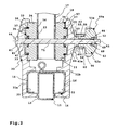
- the tensioning device 40a is in the FIGS. 1 and 2 shown while the FIGS. 3 and 4 show a nearly identical, but deviating in details tensioning device 40b.
- different components of the clamping devices 40a, 40b are indicated with the lowercase letters a or b, while the same components or similar components have the same reference numerals.
- the tensioning device 40a is used in the motor vehicle carrier primarily in the two pivot bearings 18, but could - just like the tensioning device 40b - even without further application in the two tie rods 25a, 25b, as well as the clamping nut 28 having holding devices, which is apparent from the following detailed description:
- the pivot bearings 18 each comprise two clamping brackets 30 whose clip legs 31a, 31b are fastened to the pivot supports 15. For attachment to the pivot carrier 15 receptacles 32 on the opposite clip legs 31a, 31b are provided.
- bearing mounts 33 in which bearing body 34 of a pivot bearing 35 are mounted rotatably.
- the bearing body 34 have a plug-in receptacle 36 for insertion of free ends of the bracket 17.
- the bearing body 34 are designed like a disk.
- the plug-in receptacle 36 is formed, for example, by semi-cylindrical receptacles on the bearing bodies 34, which lie opposite each other and thus form a total of a cylindrical plug-in receptacle.
- the bracket 17 is formed by a substantially cylindrical tube, the free ends are inserted into the plug receptacles 36.
- the bearing bodies 34 furthermore have annular projections 37, which engage in corresponding ring receptacles 38 on the two clip legs 31, quite specifically the bearing receptacles 33.
- the bearing body 34 may be rotated relative to the staple legs 31, but axially removed therefrom.
- Preferably 37 form fit contours 39 are provided on the ring receivers 38 and / or the annular projections, for example, serrations or the like, which engage with each other when the pivot bearings 18 are tensioned, so the bracket 17 thus rotatably establish.
- the positive locking contours 39 are disengaged, so that the bracket 17 can be pivoted relative to the pivot frame 14.
- the tensioning and loosening of the tensioning devices 40a, 40b is particularly simple according to the invention and proceeds very quickly, at the same time a firm hold or a secure tensioning position being achievable.
- the tensioning devices 40a, 40b each have a tie rod 41 onto which a nut arrangement 42a, 42b is screwed.
- the tie rods 41 further penetrate spacers 43a, 43b, which is arranged between the nut assembly 42a, 42b and a support projection 44 of the tie rod 41.
- the tie rod 41 of the clamping device 40a also penetrates the two clip legs 31a, 31b, the bearing body 34 and further (optionally) a respective free end of the bracket 17th
- the tie rod 41 also forms part of the pivot bearing 18, insofar as it provides a bearing axis 71. Thus, therefore pivots the bracket 17 pivotally mounted on the tie rods 41.
- the tie rods 41 have at a free end on a support projection 44, for example a kind of screw head or screw plate, and a tie rod threaded portion 46 on a rod portion 45.
- the tie rods 41 form clamping bolt 47th
- anti-rotation devices 50 are provided which hold the tie rods 41 against rotation when the nut 48 is screwed.
- the anti-rotation devices 50 as Polygonal contours designed, which are inserted into matching, they form-fitting receiving form-fitting receptacles.
- Such a form-fitting receptacle is provided, for example, on the clamping clip 30, for example on the clip leg 31a, in the region of the insertion opening for insertion or insertion of the tie rod 41.
- the two clip legs 31a, 31b by tightening the nut 48 on the clamping bolt 47 and the tie rod 41 or clamp together so that they act on the two bearing body 34 in the direction of the bracket 17 and this in the pivot bearing 35 and Swivel bearing 18 is held against rotation.
- a handle body 51 a, 51 b which is rotatably connected to the nut 48.
- the nut 48 is a conventional nut, i. on the outside, it has, for example, a hexagonal contour, which is received positively in a form-locking receptacle 52.
- the tie rod 41 penetrates the handle body 51a, 51b and held in the form-fitting receptacle 52 rotatably held nut 48 and is in the embodiment in front of a free end 53 of the handle body 51a, 51b, when the handle body 51a, 51b is screwed onto the tie rod 41.
- a handle body may be provided in a clamping device according to the invention, in which the tie rod or its screw engages in a blind hole-like receptacle, i. does not protrude in front of the end face of the handle body.
- the configuration chosen in the exemplary embodiments is very easy to assemble, since the nut 48 is merely inserted into the form-locking receptacle 52 and then unscrews the handle body 51a, 51b onto the tie rod 41.
- the handle body 51a, 51b which is designed knob-like, can be comfortably grasped and rotated by a user by hand. While the handle body 51a is configured as a rotary knob 54 having substantially round gripping recesses on its outer circumference, the handle body 51b has a star-shaped configuration, i.e., a circular shape. its outer circumference is essentially triangular. It is understood that the configuration of the handle body 51a, 51b is shown only by way of example.
- the spacer 43a, 43b is additionally used to enlarge or reduce a clamping distance between the clip leg 31b, which in this respect forms an abutment body 57.
- a screw body 55 is screwed into the spacer body 43a, 43b, so to speak.
- the screw body 55 is configured as a sleeve body 56.
- the screw body 55 is presently an integral part of the handle body 51a, 51b, i. with this one piece.
- the screw body 55 forms a screw extension 72 of the handle body 51a, 51b.
- the handle body 51a, 51b provides a rotationally fixed connection between the nut 48 on the one hand and the screw body 55 on the other hand.
- the screw body 55 has on its outer circumference on a threaded portion 58 which forms a second threaded portion of the nut assembly 42a or 42b extent.
- the second threaded portion 58 meshes with a spacer threaded portion 59 of the spacer 43a, 43b.
- the spacer body threaded portion 59 is provided on a sleeve portion 60 of the spacer 43a, 43b.
- the threaded portions 58, 59 have a different rotational direction than the threaded portions 46, 49.
- the two threaded portions 46, 49 right-hand thread in a conventional manner, while the threaded portions 58, 59 are left-hand threads. This allows the following functionality:
- the clamping along a tensioning axis 61 with the aid of the tensioning devices 40a, 40b according to the invention is much faster and more comfortable than with a conventional tensioning technique.
- the spacer body 43a, 43b is held against rotation, for example, from the outside, a rotation lock 62 act on him.
- the rotation lock could, for example, with axial play or axial mobility in a groove, not shown in the drawing on the spacer body 43a engage.
- an alternative solution is chosen:
- a collar-like projection 63 is arranged on the sleeve portion 60 of the spacer 43a, 43b. Furthermore, the spacer 43a, 43b on its side facing the abutment body 57 has a receptacle 64 for a projection 65 of the abutment body 57.
- the projection 65 is conical, the receptacle 64 to match also.
- the projection 63 protrudes in the manner of a collar radially in front of the sleeve portion 60 and is also arranged on the end face thereof.
- the spacer 43a, 43b has a wide support base for supporting on the abutment body 57th
- This support base which thus has a conical support surface area, is also used to prevent rotation.
- This support base which thus has a conical support surface area, is also used to prevent rotation.
- the clip legs 31a, 31b each have a reinforcing structure.
- reinforcing ribs 66 extend in a star shape away from a passage opening through which the tie rod 41 is inserted.
- the reinforcing ribs 66 initially have the function of reinforcing the plate-like regions of the clip legs 31a, 31b, so that the mechanical loading capacity of the configuration is increased.
- the reinforcing ribs 66 are namely projections 77 and thus form-fitting contours 67, which are provided for engagement in corresponding positive locking contours 68 on the spacers 43a, 43b ,
- the form-fitting contours 68 are at the spacers 43 a frontally provided on the projection 63 grooves.
- the positive locking contours 68 are configured as slots into which the reinforcing ribs 66 can engage.
- the form-fitting contours 68 present recesses 78th
- an anti-rotation of the spacer body with respect to the abutment body in a tensioning device according to the invention can also be realized by different form fit.
- bolt-like projections and matching holes on the spacer body and the abutment body or vice versa could be provided.
- one of the two nut assemblies 42a, 42b could easily be used instead of the clamping nut 28, which allow a faster tightening or loosening the clamps 24 and clamps 27.
- the invention can be used with advantage.
- a socket of a trailer hitch which can be quickly and effectively fastened by means of a tensioning device according to the invention at the rear of the motor vehicle, the coupling arm or any other suitable location and is also easily removable again.
- a further field of application could also be a locking or clamping of the ball neck with respect to a vehicle-fixed mount, wherein the ball neck can be removed, for example, from the holder or at this movable, in particular pivotally mounted.
- the release and clamping by means of a clamping device according to the invention can be used with advantage.
Landscapes
- Engineering & Computer Science (AREA)
- Mechanical Engineering (AREA)
- Transportation (AREA)
- Clamps And Clips (AREA)
Claims (15)
- Dispositif de serrage pour un support de véhicule automobile (10), en particulier un support de bicyclettes, ou pour un accouplage de remorque (92), comprenant un tirant (41) et un ensemble d'écrous (42a ; 42b) pouvant être vissé sur ledit tirant, lequel ensemble d'écrous peut être actionné par rotation et qui présente une première section filetée (49) venant en prise avec une section filetée de tirant (46) du tirant (41) afin de déplacer ladite section filetée le long d'un axe de serrage (61) de manière axiale en direction d'un corps de contre-palier (57), dans une position serrée ou dans une position desserrée à distance de ce dernier, sachant qu'est disposé entre le corps de contre-palier (57) et l'ensemble d'écrous (42a ; 42b) un corps d'espacement (43a ; 43b), caractérisé en ce que le corps d'espacement (43a ; 43b) présente une section filetée de corps d'espacement (59) présentant une direction de rotation opposée à la première direction de rotation, une deuxième section filetée (58) de l'ensemble d'écrous (42a ; 42b) coaxiale par rapport à la première section filetée (49) venant en prise avec ladite section filetée de corps d'espacement, et en ce qu'est présent entre le corps d'espacement (43a ; 43b) et une contre-bouterolle (70), en particulier le corps de contre-palier (57), un élément de liaison de friction et/ou un élément de complémentarité de forme agissant contre l'actionnement par rotation, de sorte que l'ensemble d'écrous (42a ; 42b) se visse dans le cas d'un actionnement par rotation simultanément le long du corps d'espacement (43a ; 43b) et du tirant (41), modifiant ainsi l'espacement par rapport au corps de contre-palier (57) le long de l'axe de serrage (61).
- Dispositif de serrage selon la revendication 1, caractérisé en ce que la première section filetée (49) est prévue au niveau d'un écrou (48) de l'ensemble d'écrous (42a ; 42b) et la deuxième section filetée (58) est prévue au niveau d'un corps à visser (55) de l'ensemble d'écrous (42a ; 42b), relié de manière solidaire en rotation à l'écrou (48), et/ou en ce que la première section filetée (49) de l'ensemble d'écrous (42a ; 42b) forme un filetage droit et la deuxième section filetée (58) un filetage gauche, et/ou en ce que la première section filetée (49) de l'ensemble d'écrous (42a ; 42b) est une section filetée intérieure et la deuxième section filetée (58) une section filetée extérieure ou inversement, et/ou en ce qu'au moins une des sections filetées (46, 48, 58, 59) présente un dispositif de blocage automatique.
- Dispositif de serrage selon la revendication 1 ou 2, caractérisé en ce que le corps à visser (55) comprend un corps de douille (56) traversé par le tirant (41), au niveau de la périphérie extérieure duquel est disposée la section filetée de corps d'espacement (59), et/ou en ce que l'ensemble d'écrous (42a ; 42b) présente une partie faisant saillie dépassant radialement vers l'extérieur d'une section de douille (60), en particulier un col ou une partie faisant saillie annulaire, destinée à venir en appui au niveau du corps de contre-palier (57).
- Dispositif de serrage selon l'une quelconque des revendications précédentes, caractérisé en ce que des contours de complémentarité de forme (67, 68) et/ou des butées rotatives s'adaptant les uns aux autres sont prévus au niveau du corps d'espacement (43a ; 43b) et du corps de contre-palier (57), et/ou en ce qu'au moins un contour de complémentarité de forme (67, 68) du corps de contre-palier (57) ou de l'ensemble d'écrous (42a ; 42b) est formé par une nervure de renforcement (66).
- Dispositif de serrage selon l'une quelconque des revendications précédentes, caractérisé en ce que le corps de contre-palier (57) présente aux fins du maintien par complémentarité de forme du corps d'espacement (43a ; 43b) au moins une partie faisant saillie (77) s'étendant radialement par rapport au tirant (41) ou plusieurs parties faisant saillie en forme d'étoile destinées à venir en prise avec des évidements (78) du corps d'espacement (43a ; 43b).
- Dispositif de serrage selon l'une quelconque des revendications précédentes, caractérisé en ce qu'une zone de surface d'appui de l'ensemble d'écrous (42a ; 42b) est prévue pour venir en appui au niveau du corps de contre-palier (57) au niveau d'un logement (64) conique.
- Dispositif de serrage selon l'une quelconque des revendications précédentes, caractérisé en ce que le tirant (41) est fixé de manière solidaire en rotation par rapport au corps de contre-palier (57), et/ou en ce que le tirant (41) comprend un boulon de serrage (47) ou est formé par un boulon de serrage (41), et/ou en ce que le corps de contre-palier (57) est traversé par le tirant (41), ou en ce que le tirant (41) constitue une partie intégrante du corps de contre-palier (57).
- Dispositif de serrage selon l'une quelconque des revendications précédentes, caractérisé en ce qu'il présente une bride de serrage (30), sachant que la bride de serrage (30) peut être déplacée avec l'ensemble d'écrous (42a ; 42b) entre une position fixe et une position débloquée et/ou sachant que la bride de serrage (30) constitue le corps de contre-palier (57) et/ou que la bride de serrage (30) est configurée sous la forme d'un collier de fixation.
- Dispositif de serrage selon la revendication 8, caractérisé en ce que la bride de serrage (30) comprend un palier rotatif (35) pour un élément logé par la bride de serrage (30), devant être serré, lequel est fixé par rapport à la bride de serrage (30) de manière à pouvoir tourner dans la position desserrée du dispositif de serrage (40a ; 40b) ou de manière solidaire en rotation dans la position serrée de ce dernier.
- Dispositif de serrage selon la revendication 9, caractérisé en ce que le palier rotatif (35) présente un logement d'enfichage (36) pour l'élément devant être serré, et/ou en ce que le tirant (41) constitue un axe de palier (71) du palier rotatif (35).
- Dispositif de serrage selon l'une quelconque des revendications précédentes, caractérisé en ce que l'élément devant être serré est une tige ou un étrier (17) d'un support de véhicule automobile (10).
- Dispositif de serrage selon l'une quelconque des revendications précédentes, caractérisé en ce qu'un corps de poignée (51a; 51 b) est relié de manière solidaire en rotation à l'écrou (48), ou en ce que l'écrou (48) est réalisé sous la forme d'un corps de poignée (51 a ; 51 b).
- Dispositif de serrage selon la revendication 12, caractérisé en ce que le corps de poignée (51a; 51b) présente un prolongement à visser (72), qui pénètre dans le corps d'espacement (43a ; 43b) ou dans lequel le corps d'espacement (43a ; 43b) pénètre, et/ou en ce que le corps de poignée (51 a, 51 b) présente un bouton rotatif (54).
- Support de véhicule automobile (10), en particulier support arrière et/ou un support de bicyclettes, comprenant au moins un dispositif de serrage (40a ; 40b) selon l'une quelconque des revendications précédentes, sachant que le support de véhicule (10) est ou présente de préférence un tiroir éjectable d'un hayon de véhicule automobile (90), et/ou sachant que le support de véhicule automobile (10) présente de manière appropriée un support (22) destiné à être fixé au niveau du véhicule automobile (90), en particulier un support d'attelage destiné à être fixé au niveau d'un attelage de remorque (92).
- Attelage de remorque (92) en particulier dispositif d'actionnement de l'attelage de remorque (92), comprenant au moins un dispositif de serrage (40a ; 40b) selon l'une quelconque des revendications 1 à 13.
Applications Claiming Priority (1)
| Application Number | Priority Date | Filing Date | Title |
|---|---|---|---|
| DE202010001015U DE202010001015U1 (de) | 2010-01-16 | 2010-01-16 | Spannvorrichtung für einen Kraftfahrzeug-Träger oder für eine Anhängekupplung |
Publications (2)
| Publication Number | Publication Date |
|---|---|
| EP2345558A1 EP2345558A1 (fr) | 2011-07-20 |
| EP2345558B1 true EP2345558B1 (fr) | 2013-04-17 |
Family
ID=43919771
Family Applications (1)
| Application Number | Title | Priority Date | Filing Date |
|---|---|---|---|
| EP11000188.0A Active EP2345558B1 (fr) | 2010-01-16 | 2011-01-12 | Dispositif de serrage pour un support de véhicule automobile ou pour un attelage |
Country Status (2)
| Country | Link |
|---|---|
| EP (1) | EP2345558B1 (fr) |
| DE (1) | DE202010001015U1 (fr) |
Cited By (1)
| Publication number | Priority date | Publication date | Assignee | Title |
|---|---|---|---|---|
| KR101673808B1 (ko) * | 2015-09-11 | 2016-11-08 | 현대자동차주식회사 | 차량용 자전거 캐리어 장치 |
Families Citing this family (1)
| Publication number | Priority date | Publication date | Assignee | Title |
|---|---|---|---|---|
| DE102012010049B4 (de) * | 2012-05-22 | 2015-11-26 | Springer Gmbh | Beidseitiger Schwenkarm für ein Werkstückhalteelement, insbesondere einen Werkstückgreifer insbesondere zum Halten und/oder Transportieren von Karosserieteilen im Kraftfahrzeug-Rohbau |
Family Cites Families (7)
| Publication number | Priority date | Publication date | Assignee | Title |
|---|---|---|---|---|
| DE3100595A1 (de) * | 1981-01-10 | 1982-07-29 | Herbert E. 7850 Lörrach Weichbrodt | Einrichtung zur kontinuierlichen nivellierung von maschinen, teleskopen, werkstuecken, behaeltern und anderen gegenstaenden |
| DE9214916U1 (de) * | 1992-11-03 | 1993-12-02 | Erich Uebler Autozubehörfabrik, 8821 Möhrendorf | Vorrichtung zur beabstandeten Halterung eines Fahrrads am Heckgepäckträger eines Kraftfahrzeugs |
| DE9303486U1 (de) * | 1993-03-10 | 1993-04-29 | Eufab Handelsgesellschaft für Auto- und Zweiradzubehör mbH, 5600 Wuppertal | Hecklastenträger |
| EP1095820B1 (fr) * | 1999-10-25 | 2003-10-08 | Thule Sweden AB | Porte-charges |
| ITMI20042297A1 (it) * | 2004-11-29 | 2005-02-28 | Davide Agnetti | Dispositivo per la movimentazione di componenti ottiche in sistemi ottici |
| DE102008012689A1 (de) | 2008-03-05 | 2009-09-17 | Westfalia-Automotive Gmbh | Lastenträger |
| DE202008009677U1 (de) * | 2008-07-18 | 2008-09-18 | Mft Transport Systeme Gmbh | Fahrzeugheckträger für Fahrräder mit integrierter Heckleuchtenanordnung |
-
2010
- 2010-01-16 DE DE202010001015U patent/DE202010001015U1/de not_active Expired - Lifetime
-
2011
- 2011-01-12 EP EP11000188.0A patent/EP2345558B1/fr active Active
Cited By (2)
| Publication number | Priority date | Publication date | Assignee | Title |
|---|---|---|---|---|
| KR101673808B1 (ko) * | 2015-09-11 | 2016-11-08 | 현대자동차주식회사 | 차량용 자전거 캐리어 장치 |
| US9855896B2 (en) | 2015-09-11 | 2018-01-02 | Hyundai Motor Company | Bicycle carrier apparatus for vehicle |
Also Published As
| Publication number | Publication date |
|---|---|
| DE202010001015U1 (de) | 2011-05-26 |
| EP2345558A1 (fr) | 2011-07-20 |
Similar Documents
| Publication | Publication Date | Title |
|---|---|---|
| EP2804801B1 (fr) | Colonne de direction pour un véhicule automobile | |
| EP1671527B1 (fr) | Elément de liason | |
| DE10147588B4 (de) | Befestigungskloben zur Halterung von Gegenständen an einer Profilschiene | |
| EP3409502A1 (fr) | Masse d'alourdissement de roue pour un véhicule utilitaire | |
| EP2292471B1 (fr) | Dispositif de fixation doté d'un étrier | |
| DE102009039822A1 (de) | Befestigungseinrichtung mit einer Spannmutteranordnung | |
| DE102009022622A1 (de) | Kraftfahrzeuganbaukomponente, insbesondere Lastenträger oder Anhängerkupplung | |
| DE2239853B2 (de) | Haltevorrichtung fuer aussenrueckblickspiegel von kraftfahrzeugen o.dgl. | |
| EP2345558B1 (fr) | Dispositif de serrage pour un support de véhicule automobile ou pour un attelage | |
| EP2497701A1 (fr) | Plateforme pivotante pour un véhicule articulé | |
| EP1544003B1 (fr) | Dispositif d'attelage pour véhicules automobiles | |
| DE202016101843U1 (de) | Sperrbalken | |
| DE602005000229T2 (de) | Vorrichtung zur lösbaren Verriegelung eines Endstückes auf einer Struktur mit verstellbarer Position | |
| DE102013211404B3 (de) | Haltevorrichtung zum Halten eines Fahrrads | |
| DE102011083358A1 (de) | Spannvorrichtung, insbesondere für einen Dachträger eines Kraftfahrzeugs | |
| EP2292469B1 (fr) | Dispositif de fixation doté d'un étrier | |
| DE202017103040U1 (de) | Trägeranordnung für ein Fahrzeug | |
| DE10309087A1 (de) | Befestigungseinrichtung für Kraftfahrzeug-Scheinwerfer | |
| EP3362340B1 (fr) | Dispositif de retenue et moyen d'emballage adapté | |
| DE202005011163U1 (de) | Heckträger, insbesondere für Fahrräder | |
| EP1634774B1 (fr) | Porte-charge pour un dispositif d'attelage rétractable | |
| DE102024127813A1 (de) | Höhenverstellbarer Lenkervorbau-Adapter mit Verdrehfunktion | |
| DE202005011162U1 (de) | Heckträger, insbesondere für Fahrräder | |
| DE202005002938U1 (de) | Vorrichtung zur zusätzlichen Transportsicherung von Fahrrädern an Kraftfahrzeug-Gepäckträgern | |
| DE202006014301U1 (de) | Gepäckträger |
Legal Events
| Date | Code | Title | Description |
|---|---|---|---|
| PUAI | Public reference made under article 153(3) epc to a published international application that has entered the european phase |
Free format text: ORIGINAL CODE: 0009012 |
|
| AK | Designated contracting states |
Kind code of ref document: A1 Designated state(s): AL AT BE BG CH CY CZ DE DK EE ES FI FR GB GR HR HU IE IS IT LI LT LU LV MC MK MT NL NO PL PT RO RS SE SI SK SM TR |
|
| AX | Request for extension of the european patent |
Extension state: BA ME |
|
| 17P | Request for examination filed |
Effective date: 20111207 |
|
| GRAP | Despatch of communication of intention to grant a patent |
Free format text: ORIGINAL CODE: EPIDOSNIGR1 |
|
| RIC1 | Information provided on ipc code assigned before grant |
Ipc: B60R 9/06 20060101AFI20121026BHEP Ipc: B60R 9/058 20060101ALI20121026BHEP Ipc: B60D 1/52 20060101ALI20121026BHEP Ipc: B60D 1/64 20060101ALI20121026BHEP Ipc: B60R 9/10 20060101ALI20121026BHEP |
|
| GRAS | Grant fee paid |
Free format text: ORIGINAL CODE: EPIDOSNIGR3 |
|
| GRAA | (expected) grant |
Free format text: ORIGINAL CODE: 0009210 |
|
| AK | Designated contracting states |
Kind code of ref document: B1 Designated state(s): AL AT BE BG CH CY CZ DE DK EE ES FI FR GB GR HR HU IE IS IT LI LT LU LV MC MK MT NL NO PL PT RO RS SE SI SK SM TR |
|
| REG | Reference to a national code |
Ref country code: GB Ref legal event code: FG4D Free format text: NOT ENGLISH |
|
| REG | Reference to a national code |
Ref country code: CH Ref legal event code: EP |
|
| REG | Reference to a national code |
Ref country code: IE Ref legal event code: FG4D Free format text: LANGUAGE OF EP DOCUMENT: GERMAN |
|
| REG | Reference to a national code |
Ref country code: AT Ref legal event code: REF Ref document number: 607051 Country of ref document: AT Kind code of ref document: T Effective date: 20130515 |
|
| REG | Reference to a national code |
Ref country code: DE Ref legal event code: R096 Ref document number: 502011000601 Country of ref document: DE Effective date: 20130613 |
|
| REG | Reference to a national code |
Ref country code: LT Ref legal event code: MG4D |
|
| REG | Reference to a national code |
Ref country code: NL Ref legal event code: VDEP Effective date: 20130417 |
|
| PG25 | Lapsed in a contracting state [announced via postgrant information from national office to epo] |
Ref country code: PT Free format text: LAPSE BECAUSE OF FAILURE TO SUBMIT A TRANSLATION OF THE DESCRIPTION OR TO PAY THE FEE WITHIN THE PRESCRIBED TIME-LIMIT Effective date: 20130819 Ref country code: NO Free format text: LAPSE BECAUSE OF FAILURE TO SUBMIT A TRANSLATION OF THE DESCRIPTION OR TO PAY THE FEE WITHIN THE PRESCRIBED TIME-LIMIT Effective date: 20130717 Ref country code: SI Free format text: LAPSE BECAUSE OF FAILURE TO SUBMIT A TRANSLATION OF THE DESCRIPTION OR TO PAY THE FEE WITHIN THE PRESCRIBED TIME-LIMIT Effective date: 20130417 Ref country code: IS Free format text: LAPSE BECAUSE OF FAILURE TO SUBMIT A TRANSLATION OF THE DESCRIPTION OR TO PAY THE FEE WITHIN THE PRESCRIBED TIME-LIMIT Effective date: 20130817 Ref country code: LT Free format text: LAPSE BECAUSE OF FAILURE TO SUBMIT A TRANSLATION OF THE DESCRIPTION OR TO PAY THE FEE WITHIN THE PRESCRIBED TIME-LIMIT Effective date: 20130417 Ref country code: ES Free format text: LAPSE BECAUSE OF FAILURE TO SUBMIT A TRANSLATION OF THE DESCRIPTION OR TO PAY THE FEE WITHIN THE PRESCRIBED TIME-LIMIT Effective date: 20130728 Ref country code: FI Free format text: LAPSE BECAUSE OF FAILURE TO SUBMIT A TRANSLATION OF THE DESCRIPTION OR TO PAY THE FEE WITHIN THE PRESCRIBED TIME-LIMIT Effective date: 20130417 Ref country code: GR Free format text: LAPSE BECAUSE OF FAILURE TO SUBMIT A TRANSLATION OF THE DESCRIPTION OR TO PAY THE FEE WITHIN THE PRESCRIBED TIME-LIMIT Effective date: 20130718 Ref country code: SE Free format text: LAPSE BECAUSE OF FAILURE TO SUBMIT A TRANSLATION OF THE DESCRIPTION OR TO PAY THE FEE WITHIN THE PRESCRIBED TIME-LIMIT Effective date: 20130417 |
|
| PG25 | Lapsed in a contracting state [announced via postgrant information from national office to epo] |
Ref country code: RS Free format text: LAPSE BECAUSE OF FAILURE TO SUBMIT A TRANSLATION OF THE DESCRIPTION OR TO PAY THE FEE WITHIN THE PRESCRIBED TIME-LIMIT Effective date: 20130417 Ref country code: LV Free format text: LAPSE BECAUSE OF FAILURE TO SUBMIT A TRANSLATION OF THE DESCRIPTION OR TO PAY THE FEE WITHIN THE PRESCRIBED TIME-LIMIT Effective date: 20130417 Ref country code: PL Free format text: LAPSE BECAUSE OF FAILURE TO SUBMIT A TRANSLATION OF THE DESCRIPTION OR TO PAY THE FEE WITHIN THE PRESCRIBED TIME-LIMIT Effective date: 20130417 Ref country code: HR Free format text: LAPSE BECAUSE OF FAILURE TO SUBMIT A TRANSLATION OF THE DESCRIPTION OR TO PAY THE FEE WITHIN THE PRESCRIBED TIME-LIMIT Effective date: 20130417 Ref country code: CY Free format text: LAPSE BECAUSE OF FAILURE TO SUBMIT A TRANSLATION OF THE DESCRIPTION OR TO PAY THE FEE WITHIN THE PRESCRIBED TIME-LIMIT Effective date: 20130417 Ref country code: BG Free format text: LAPSE BECAUSE OF FAILURE TO SUBMIT A TRANSLATION OF THE DESCRIPTION OR TO PAY THE FEE WITHIN THE PRESCRIBED TIME-LIMIT Effective date: 20130717 |
|
| PG25 | Lapsed in a contracting state [announced via postgrant information from national office to epo] |
Ref country code: CZ Free format text: LAPSE BECAUSE OF FAILURE TO SUBMIT A TRANSLATION OF THE DESCRIPTION OR TO PAY THE FEE WITHIN THE PRESCRIBED TIME-LIMIT Effective date: 20130417 Ref country code: SK Free format text: LAPSE BECAUSE OF FAILURE TO SUBMIT A TRANSLATION OF THE DESCRIPTION OR TO PAY THE FEE WITHIN THE PRESCRIBED TIME-LIMIT Effective date: 20130417 Ref country code: DK Free format text: LAPSE BECAUSE OF FAILURE TO SUBMIT A TRANSLATION OF THE DESCRIPTION OR TO PAY THE FEE WITHIN THE PRESCRIBED TIME-LIMIT Effective date: 20130417 Ref country code: EE Free format text: LAPSE BECAUSE OF FAILURE TO SUBMIT A TRANSLATION OF THE DESCRIPTION OR TO PAY THE FEE WITHIN THE PRESCRIBED TIME-LIMIT Effective date: 20130417 |
|
| PLBE | No opposition filed within time limit |
Free format text: ORIGINAL CODE: 0009261 |
|
| STAA | Information on the status of an ep patent application or granted ep patent |
Free format text: STATUS: NO OPPOSITION FILED WITHIN TIME LIMIT |
|
| PG25 | Lapsed in a contracting state [announced via postgrant information from national office to epo] |
Ref country code: RO Free format text: LAPSE BECAUSE OF FAILURE TO SUBMIT A TRANSLATION OF THE DESCRIPTION OR TO PAY THE FEE WITHIN THE PRESCRIBED TIME-LIMIT Effective date: 20130417 Ref country code: NL Free format text: LAPSE BECAUSE OF FAILURE TO SUBMIT A TRANSLATION OF THE DESCRIPTION OR TO PAY THE FEE WITHIN THE PRESCRIBED TIME-LIMIT Effective date: 20130417 Ref country code: IT Free format text: LAPSE BECAUSE OF FAILURE TO SUBMIT A TRANSLATION OF THE DESCRIPTION OR TO PAY THE FEE WITHIN THE PRESCRIBED TIME-LIMIT Effective date: 20130417 |
|
| 26N | No opposition filed |
Effective date: 20140120 |
|
| REG | Reference to a national code |
Ref country code: DE Ref legal event code: R097 Ref document number: 502011000601 Country of ref document: DE Effective date: 20140120 |
|
| BERE | Be: lapsed |
Owner name: WESTFALIA - AUTOMOTIVE G.M.B.H. Effective date: 20140131 |
|
| PG25 | Lapsed in a contracting state [announced via postgrant information from national office to epo] |
Ref country code: LU Free format text: LAPSE BECAUSE OF FAILURE TO SUBMIT A TRANSLATION OF THE DESCRIPTION OR TO PAY THE FEE WITHIN THE PRESCRIBED TIME-LIMIT Effective date: 20140112 |
|
| REG | Reference to a national code |
Ref country code: CH Ref legal event code: PL |
|
| REG | Reference to a national code |
Ref country code: DE Ref legal event code: R082 Ref document number: 502011000601 Country of ref document: DE Representative=s name: BREGENZER, MICHAEL, DIPL.-ING., DE Ref country code: DE Ref legal event code: R082 Ref document number: 502011000601 Country of ref document: DE Representative=s name: PATENTANWAELTE BREGENZER UND REULE PARTNERSCHA, DE |
|
| PG25 | Lapsed in a contracting state [announced via postgrant information from national office to epo] |
Ref country code: CH Free format text: LAPSE BECAUSE OF NON-PAYMENT OF DUE FEES Effective date: 20140131 Ref country code: LI Free format text: LAPSE BECAUSE OF NON-PAYMENT OF DUE FEES Effective date: 20140131 |
|
| REG | Reference to a national code |
Ref country code: IE Ref legal event code: MM4A |
|
| REG | Reference to a national code |
Ref country code: DE Ref legal event code: R082 Ref document number: 502011000601 Country of ref document: DE Representative=s name: PATENTANWAELTE BREGENZER UND REULE PARTNERSCHA, DE |
|
| PG25 | Lapsed in a contracting state [announced via postgrant information from national office to epo] |
Ref country code: BE Free format text: LAPSE BECAUSE OF NON-PAYMENT OF DUE FEES Effective date: 20140131 Ref country code: IE Free format text: LAPSE BECAUSE OF NON-PAYMENT OF DUE FEES Effective date: 20140112 |
|
| PG25 | Lapsed in a contracting state [announced via postgrant information from national office to epo] |
Ref country code: MC Free format text: LAPSE BECAUSE OF FAILURE TO SUBMIT A TRANSLATION OF THE DESCRIPTION OR TO PAY THE FEE WITHIN THE PRESCRIBED TIME-LIMIT Effective date: 20130417 |
|
| GBPC | Gb: european patent ceased through non-payment of renewal fee |
Effective date: 20150112 |
|
| PG25 | Lapsed in a contracting state [announced via postgrant information from national office to epo] |
Ref country code: GB Free format text: LAPSE BECAUSE OF NON-PAYMENT OF DUE FEES Effective date: 20150112 |
|
| REG | Reference to a national code |
Ref country code: FR Ref legal event code: PLFP Year of fee payment: 6 |
|
| PG25 | Lapsed in a contracting state [announced via postgrant information from national office to epo] |
Ref country code: MT Free format text: LAPSE BECAUSE OF FAILURE TO SUBMIT A TRANSLATION OF THE DESCRIPTION OR TO PAY THE FEE WITHIN THE PRESCRIBED TIME-LIMIT Effective date: 20130417 |
|
| PG25 | Lapsed in a contracting state [announced via postgrant information from national office to epo] |
Ref country code: SM Free format text: LAPSE BECAUSE OF FAILURE TO SUBMIT A TRANSLATION OF THE DESCRIPTION OR TO PAY THE FEE WITHIN THE PRESCRIBED TIME-LIMIT Effective date: 20130417 |
|
| PG25 | Lapsed in a contracting state [announced via postgrant information from national office to epo] |
Ref country code: HU Free format text: LAPSE BECAUSE OF FAILURE TO SUBMIT A TRANSLATION OF THE DESCRIPTION OR TO PAY THE FEE WITHIN THE PRESCRIBED TIME-LIMIT; INVALID AB INITIO Effective date: 20110112 Ref country code: TR Free format text: LAPSE BECAUSE OF FAILURE TO SUBMIT A TRANSLATION OF THE DESCRIPTION OR TO PAY THE FEE WITHIN THE PRESCRIBED TIME-LIMIT Effective date: 20130417 |
|
| REG | Reference to a national code |
Ref country code: FR Ref legal event code: PLFP Year of fee payment: 7 |
|
| REG | Reference to a national code |
Ref country code: AT Ref legal event code: MM01 Ref document number: 607051 Country of ref document: AT Kind code of ref document: T Effective date: 20160112 |
|
| PG25 | Lapsed in a contracting state [announced via postgrant information from national office to epo] |
Ref country code: AT Free format text: LAPSE BECAUSE OF NON-PAYMENT OF DUE FEES Effective date: 20160112 |
|
| REG | Reference to a national code |
Ref country code: FR Ref legal event code: PLFP Year of fee payment: 8 |
|
| PG25 | Lapsed in a contracting state [announced via postgrant information from national office to epo] |
Ref country code: MK Free format text: LAPSE BECAUSE OF FAILURE TO SUBMIT A TRANSLATION OF THE DESCRIPTION OR TO PAY THE FEE WITHIN THE PRESCRIBED TIME-LIMIT Effective date: 20130417 |
|
| PG25 | Lapsed in a contracting state [announced via postgrant information from national office to epo] |
Ref country code: AL Free format text: LAPSE BECAUSE OF FAILURE TO SUBMIT A TRANSLATION OF THE DESCRIPTION OR TO PAY THE FEE WITHIN THE PRESCRIBED TIME-LIMIT Effective date: 20130417 |
|
| PGFP | Annual fee paid to national office [announced via postgrant information from national office to epo] |
Ref country code: FR Payment date: 20211202 Year of fee payment: 12 |
|
| PG25 | Lapsed in a contracting state [announced via postgrant information from national office to epo] |
Ref country code: FR Free format text: LAPSE BECAUSE OF NON-PAYMENT OF DUE FEES Effective date: 20230131 |
|
| PGFP | Annual fee paid to national office [announced via postgrant information from national office to epo] |
Ref country code: DE Payment date: 20260128 Year of fee payment: 16 |