EP2345765B1 - Water saving disc - Google Patents
Water saving disc Download PDFInfo
- Publication number
- EP2345765B1 EP2345765B1 EP08877784.2A EP08877784A EP2345765B1 EP 2345765 B1 EP2345765 B1 EP 2345765B1 EP 08877784 A EP08877784 A EP 08877784A EP 2345765 B1 EP2345765 B1 EP 2345765B1
- Authority
- EP
- European Patent Office
- Prior art keywords
- water
- cylinder
- water saving
- wall
- air
- Prior art date
- Legal status (The legal status is an assumption and is not a legal conclusion. Google has not performed a legal analysis and makes no representation as to the accuracy of the status listed.)
- Active
Links
Images


Classifications
-
- E—FIXED CONSTRUCTIONS
- E03—WATER SUPPLY; SEWERAGE
- E03C—DOMESTIC PLUMBING INSTALLATIONS FOR FRESH WATER OR WASTE WATER; SINKS
- E03C1/00—Domestic plumbing installations for fresh water or waste water; Sinks
- E03C1/02—Plumbing installations for fresh water
- E03C1/08—Jet regulators or jet guides, e.g. anti-splash devices
- E03C1/084—Jet regulators with aerating means
-
- B—PERFORMING OPERATIONS; TRANSPORTING
- B05—SPRAYING OR ATOMISING IN GENERAL; APPLYING FLUENT MATERIALS TO SURFACES, IN GENERAL
- B05B—SPRAYING APPARATUS; ATOMISING APPARATUS; NOZZLES
- B05B15/00—Details of spraying plant or spraying apparatus not otherwise provided for; Accessories
- B05B15/60—Arrangements for mounting, supporting or holding spraying apparatus
- B05B15/65—Mounting arrangements for fluid connection of the spraying apparatus or its outlets to flow conduits
-
- B—PERFORMING OPERATIONS; TRANSPORTING
- B05—SPRAYING OR ATOMISING IN GENERAL; APPLYING FLUENT MATERIALS TO SURFACES, IN GENERAL
- B05B—SPRAYING APPARATUS; ATOMISING APPARATUS; NOZZLES
- B05B7/00—Spraying apparatus for discharge of liquids or other fluent materials from two or more sources, e.g. of liquid and air, of powder and gas
- B05B7/02—Spray pistols; Apparatus for discharge
- B05B7/04—Spray pistols; Apparatus for discharge with arrangements for mixing liquids or other fluent materials before discharge
- B05B7/0416—Spray pistols; Apparatus for discharge with arrangements for mixing liquids or other fluent materials before discharge with arrangements for mixing one gas and one liquid
- B05B7/0425—Spray pistols; Apparatus for discharge with arrangements for mixing liquids or other fluent materials before discharge with arrangements for mixing one gas and one liquid without any source of compressed gas, e.g. the air being sucked by the pressurised liquid
-
- Y—GENERAL TAGGING OF NEW TECHNOLOGICAL DEVELOPMENTS; GENERAL TAGGING OF CROSS-SECTIONAL TECHNOLOGIES SPANNING OVER SEVERAL SECTIONS OF THE IPC; TECHNICAL SUBJECTS COVERED BY FORMER USPC CROSS-REFERENCE ART COLLECTIONS [XRACs] AND DIGESTS
- Y02—TECHNOLOGIES OR APPLICATIONS FOR MITIGATION OR ADAPTATION AGAINST CLIMATE CHANGE
- Y02A—TECHNOLOGIES FOR ADAPTATION TO CLIMATE CHANGE
- Y02A20/00—Water conservation; Efficient water supply; Efficient water use
- Y02A20/40—Protecting water resources
- Y02A20/411—Water saving techniques at user level
Definitions
- This invention relates to a water saving aerator attached to the water delivery devices such as a water tap (including a general water tap and a special purpose water tap for laboratory use) and a shower head for saving the amount of the water flow and aerating the water for generating bubble foam water.
- a water tap including a general water tap and a special purpose water tap for laboratory use
- a shower head for saving the amount of the water flow and aerating the water for generating bubble foam water.
- the water saving is required in many settings including ordinary homes and in commercial facilities.
- One of the water saving methods is attaching a water saving disc to the water delivery devices such as a water tap.
- the water saving disc in the prior art is attached to the water delivery devices by installing the pillar-shaped disc inside of the water tap. The amount of the water flow is decreased by narrowing the water flow diameter with the water saving disc even if the opening diameter of the water tap is large.
- the basic shape of the conventional water saving disc is a pillar-shape corresponding to the cylindrical water pipe and the through-hole penetrates from the upper surface to the lower surface of the pillar-shape water saving disc.
- the number of the through-hole is not limited to one, and two or three through-holes can be arranged in the conventional water saving disc.
- the conventional water saving disc described in the JP H09-095985 comprises a pillar-shaped water saving disc and at least three through-holes formed through from the upper surface to the lower surface.
- These through-holes can have a certain skew relative to each other.
- the distance between the through-holes on the upper surface is small, and the distance between the through-holes on the lower surface becomes large corresponding to its height.
- the large flange is formed on the upper surface edge, so the conventional water saving disc can be installed in the water tap.
- Three through-holes are formed through the water saving disc, and these though holes are arranged in a concentric circle.
- US 3 664 589 A describes an aerating device for entraining air in water flowing through a conduit.
- NL 7206 141 A describes a water diffuser in which water drops are discharged directly after diffusing.
- US 3286935 A describes a combined liquid spray and aerator.
- the conventional aeration mechanism utilizes the side hole formed in the side wall for aerating the outer air into the water flow running in front of the hole. In this conventional aeration mechanism, only a small amount of air can be aerated to the water flow and an insufficient quality level of the bubble foam water is obtained.
- the conventional water saving disc described in JP H09-095985 has the following problem.
- the conventional water saving disc utilizes the through-hole having the small diameter smaller than that of the water tap, so the passage diameter of the water flow becomes small.
- the water flow coming from such a small through-hole becomes very fast and strong water flow because of the high water pressure provided in the water tap, and sometimes, the water flow becomes too strong to use.
- the water flow from the through-hole with small diameter becomes intensely strong, and sometimes the water flow becomes so strong as to cause pain when putting a hand in the water flow. This problem has occurred when utilizing the small diameter through-hole smaller than that of the water tap.
- the conventional water saving disc described in the JP Utility model 3114347 can aerate the small amount of air near the side hole to the water flow running through the water tap, and only a small amount of air can be aerated to the outer surface of the water flow, so the generated bubble foam water includes an insufficient amount of air.
- the present invention provides a water saving aerator having the features of claim 1.
- the diffuser object is extended from and suspended from the lower surface of the water saving disc, the diffuser object comprising a diffuser plate having certain skew from the center highest portion to the peripheral lowest portion, and the diffuser plate is located in the place facing the through-hole of the water saving disc.
- the diffuser object diffuses the water flow coming from the through-hole in the peripheral direction.
- the first cylinder covers the diffuser object from the outside, the water pass is formed between the outer wall of the diffuser object and the inner wall of the first cylinder, and the water flow diffused by the diffuser object is received by the inner wall of the first cylinder and led to the lower water pass.
- the above-mentioned configuration of the invention of the water saving aerator can obtain the water saving effect by decreasing the total water outflow cross-sectional area to be less than the water tap inflow cross-sectional area, weaken the water flow appropriately by the diffuser object and lead the water down along the inner surface of the first cylinder.
- the speed of the water flow can be adjusted appropriately.
- the present invention of a water saving aerator further comprises an air cavity connected to the outer air that is provided in the first cylinder under the water saving disc.
- the water flow is injected to the air in the air cavity from the through-hole of the water saving disc and the water flow is led to the diffuser object through the air present in the air cavity, the bubble foam water is generated by aerating the air into the water flow injected by the water saving disc, diffusing the water flow in the peripheral direction by the diffuser object, and leading the water flow to the lower water pass by the first cylinder.
- the water saving aerator further comprises a second cylinder covering the first cylinder from the outside and providing a gap between the inner wall of the second cylinder and the outer wall of the first cylinder.
- the water saving aerator further comprises an air intake hole formed on the upper portion of the wall of the first cylinder higher than the diffuser object; wherein the ventilation pass for ventilating the outer air is formed by the gap between the inner wall of the second cylinder and the outer wall of the first cylinder to the air cavity via the air intake hole, and the air flow blown into the air cavity through the ventilation pass via the air intake hole is obtained by utilizing the low air pressure decreased by the water flow and the air flow from the air cavity to the water pass.
- the above-mentioned configuration of the invention of the water saving aerator it can obtain the bubble foam water by aerating a lot of air into the water in the water saving aerator.
- the water flow is injected from the through-hole of the water saving disc to the air present in the air cavity, the injected water flow, not to touch the inner wall of the first cylinder, hits the diffuser object directly for diffusing and aerating the air, as a result, the high quality bubble foam water can be generated by aerating a lot of air into the water flow.
- the airtightness of the first cylinder is enhanced by contacting the lower surface of the water saving disc and the upper surface of the first cylinder in order to limit the water inflow opening to the air cavity as the through-hole and limit the ventilation air inflow opening of the air cavity as the air intake hole.
- the water saving aerator further comprises; a fastening object for pulling up and fixing the second cylinder to the water tap; a flange formed on the upper surface of the first cylinder for contacting the lower surface of the water saving disc; a flange stopper formed on the inner wall of the second cylinder facing to the flange of the first cylinder, wherein the three components such as the flange of the first cylinder, the flange stopper of the second cylinder and the lower surface of the water saving disc are fastened and pulled up by the fastening object, and the upper surface of the water saving disc is pressed to the water tap.
- the water saving aerator further comprises a gasket inserted between the upper surface of the water saving disc and the water tap, wherein the water saving disc is pulled up, the gasket is deformed between the upper surface of the water saving disc and the water tap, and the fine airtightness between the upper surface and the water tap can be enhanced by pressing the outer edge of the gasket to the inner wall of the first cylinder.
- the water saving disc is pressed to the outflow opening of the water tap tightly, there is no water leaking from the side portion of the water saving disc by the water pressure provided by the water tap.
- the fastening object comprises an inner flange facing to the upper edge of the second cylinder, and a gasket inserted between the inner flange of the fastening-up object and the upper edge of the second cylinder, wherein the gasket is deformed by being pressed by the upper edge of the second cylinder, and the friction force is generated between the outer edge of the first gasket and the inner wall of the fastening object.
- the friction force is generated between the inner edge of the gasket and the outer wall of the water tap.
- the friction force is generated between the outer edge of the gasket and the inner wall of the fastening-up object.
- the friction force is generated between the inner edge of the gasket and the outer wall of the water tap, and the water saving aerator is installed and fixed firmly to the water tap without dropping off.
- the water saving aerator of the present invention can achieve the sufficient water saving effect by narrowing down the water flow cross-sectional area from the water flow cross-sectional area, and it can decrease the speed of the water flow moderately with the diffuser object and turn the water flow along toward the inner wall of the first cylinder and moderate the speed of the water flow appropriately.
- the water saving aerator of the present invention can make high quality bubble foam water by aerating the air to the water flow appropriately.
- the air intake is conducted via the intake hole utilizing the air pressure difference generated by the water flow.
- the water flow runs through the center portion of the water saving aerator keeping distance from the intake hole in order to prevent the water flow flushing back from the intake hole.
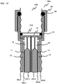
- FIG.1 is a schematic view of the water saving aerator 100 in embodiment 1.
- the water saving aerator 100 shown in Embodiment 1 can save water and generate the bubble foam water.
- the water saving aerator 100 of the present invention includes the water saving disc 10, the diffuser object 20, the first cylinder 30, the second cylinder 40, the fastening object 50, the first gasket 60 and the second gasket 61.
- Fig.1 all components such as the water saving disc 10, the diffuser object 20, the first cylinder 30, the second cylinder 40, the fastening object 50, the first gasket 60 and the second gasket 61 are shown in the cross-section view.
- the water tap 200 is shown by the front view, not by the cross-sectional view.
- the air cavity 70 and the water pass 71 and the ventilation pass 72 are formed as the space between the above-mentioned components.
- Fig.2 is an exploded view showing the water saving disc 10 and the diffuser object 20
- Fig.3 is an exploded view showing the first cylinder 30
- Fig.4 is an exploded view showing the second cylinder 40
- Fig.5 is an exploded view showing the fastening object 50.
- the basic shape is a plan as disc shape, and the diameter of the water saving disc 10 is the same as that of the outer edge of the outflow opening 210 of the water tap 200. Therefore, the water saving disc 10 is selected corresponding to the shape and the size of the outflow opening of the water tap 200.
- most of the water taps are standardized according to use. For example, in most cases, the shape and the size of the water taps used in the same facility or used in the same school are unified.
- the water saving disc 10 comprises at least one through-hole 11 penetrating from upper surface to the bottom surface.
- the water saving disc 10 covers the outflow opening 210 of the water tap 200 by the upper surface and injects the water flow from the through-hole 11.
- the through-hole 11 is a hole penetrating the pillar in the vertical direction, so the water flow goes straight in the vertical direction.
- the angle of the through-hole 11 is not limited to the vertical direction; a skewed angle can be possible as long as the water flow hits the diffuser plate 21 of the diffuser object 21.
- the water saving effect can be achieved by narrowing the outflow cross-sectional area of the water flow to be smaller than the inflow cross-sectional area of the water flow by covering the opening 210 of the water tap 200 by the water saving disc 10.
- the diffuser object 20 is a structure extended from the lower surface of the water saving disc 10 as shown in Fig.2 .
- the diffuser object 20 is suspended from the lower surface of the water saving disc 10 and the diffuser object 20 is hit by the water flow from the through-hole 11.
- the diffuser object 20 comprises a diffuser plate 21 that diffuses the water flow in the peripheral direction, an extension object 22 extended from the lower surface of the water saving disc 10, a lower object 23 extended from the lower portion of the diffuser plate 21.
- the diffuser plate 21 is a plate having certain skew for receiving the water flow coming from the through-hole 11 and diffusing the water flow in the peripheral direction.
- the diffuser plate 21 has about a 45 degree angle for receiving the water flow coming from the through-hole 11 and diffusing the water flow to the peripheral direction.
- the extension object 22 is a bridge portion for connecting the lower surface of the water saving disc 10 and the diffuser plate 21.
- the shape of the extension object 22 is not limited to this example. In this configuration, the shape of the extension object 22 is a thin pillar-shape. However, the number of the extension object 22 is not limited to one. Two or more extension objects 22 can be used. In addition, the extension object 22 is not necessary as the independent module if the diffuser plate 21 is connected directly to the lower surface of the water saving disc 10.
- the lower object 23 is the structure facing to the inner surface of the first cylinder 30 for forming the water pass 71 for the water flow running along the inner surface of the first cylinder 30.
- the water flow coming from the through-hole 11 of the water saving disc 10 is diffused by the diffuser object 20 in the peripheral direction and goes into the water pass 71 along the inner surface of the first cylinder 30.
- the water pass 71 is formed between the lower object 23 and the inner surface of the first cylinder 30.
- the first cylinder 30 is a structure for covering the outer edge of the diffuser object 20.
- the first cylinder 30 receives the diffused water from the diffuser object 20 and leads the water down along the inner surface.
- the first cylinder 30 comprises a flange 31 at the upper edge, a cylinder object 32 extended from the flange 31, plurality of air intake holes 33 in the upper side wall of the cylinder object 32 and an inner space 34 in the cylinder object 32.
- the upper surface of the flange 31 is covered by the water saving disc 10, and the diffuser object 20 is present within the inner wall of the first cylinder 30.
- the space 34 between the lower surface of the water saving disc 10 and the upper surface of the diffuser plate 21 forms the air cavity 70.
- the gap between the inner wall of the cylinder 32 and the lower object 23 of the diffuser object 20 in the space 34 in the cylinder object 32 forms the water pass 71.
- the water flow coming from the water tap 200 via the through-hole 11 of the water saving disc 10 is diffused by the diffuser object 20 in the peripheral direction and goes into the water pass 71.
- the first cylinder 30 achieves two functions. One is the function for providing the water pass for the water flow diffused by the diffuser object 20, the other is the function for generating the bubble foam water by cooperating with the second cylinder 40 as described later.
- the air intake hole 33 is located in the upper portion of the wall of the first cylinder 30 higher than the diffuser plate 21 of the diffuser object 20 when the diffuser object 20 is combined with the first cylinder 30.
- the second cylinder 40 covers the outer surface of the first cylinder 30 and forms the ventilation pass 72 between the inner surface of the second cylinder 40 and the outer surface of the first cylinder 30.
- the second cylinder 40 comprises a upper cylinder object 41, a upper edge 42 of the upper cylinder object 41, an external thread 43 formed on the outer surface of the upper cylinder object 41, a flange stopper 44 formed in the upper cylinder object 41, an inner space 45 of the upper cylinder object 41, a lower cylinder object 46, a corrugated outer surface 47 formed on the outer wall of the lower cylinder object 46 and an inner space 48 of the lower cylinder object 46.
- the second cylinder 40 supports the flange 31 with the flange stopper 44.
- the second cylinder 40 covers the first cylinder 30, and the water saving disc 10 and the flange 31 of the first cylinder 30 are located in the space 45 in the upper cylinder object 41 of the second cylinder 40.
- the cylinder object 32 of the first cylinder 30 is located in the space 48 of the lower cylinder object 46 of the second cylinder 40.
- the ventilation pass 72 ventilating the outer air to the intake hole 33 is formed between the outer surface of the cylinder object 32 and the inner surface of the lower cylinder object 46 as described later.
- This ventilation pass 72 runs through from the opening of the lower surface of the water saving aerator 100 via the gap between the outer surface of the first cylinder 30 and the inner surface of the second cylinder 40 to the air intake hole 33 around the upper portion of the first cylinder 30.
- Fig.6 is a schematic view showing the water flow and the air flow running through the water saving aerator 100.
- the narrowing water flow is injected from the opening 210 of the water tap 200 to the air cavity 70 via the through-hole 11 of the water saving disc 10.
- the water flow hits the diffuser plate 21 of the diffuser object 20, and the water flow is diffused by the diffuser plate 21.
- the water flow diffused by the diffuser plate 21 of the diffuser object 20 in the peripheral direction goes into the water pass 71 formed between the inner surface of the first cylinder 30 and the lower object 23 of the diffuser object 20.
- the air pressure of the air cavity 70 in the first cylinder 30 is decreased by the water flow.
- the ventilation force at the air intake hole 33 around the upper portion of the first cylinder 30 is provided by the decrease of the inner air pressure of the air cavity 70.
- the air intake hole 33 is connected to the atmosphere via the ventilation pass 72, the outer air enters the air cavity 70 of the first cylinder 30 via the air intake hole 33.
- the water saving aerator 100 receives the water flow from the water tap 200, narrows down the water flow with the water saving disc 10, injects the water flow to the air in the air cavity 70, and diffuses the injected water flow in the peripheral direction with the diffuser object 20. In this manner, the water saving aerator 100 generates the high quality bubble foam water by mixing the air into the water flow running through the water pass 71.
- the airtightness is required between each component.
- the fine airtightness is required at least at the following two portions.
- the fine airtightness is required between these two components, because if there is not enough fine airtightness, the water flow leaks from not only the through-hole 11 of the water saving disc 10 but also the side gap on the upper surface of the water saving disc 10, and a water leaking problem can be caused by the water pressure of the water tap 200.
- the fastening object 50 covers the outer surface of the second cylinder 40 and fastens the second cylinder 40, the first cylinder 30 and the water saving disc 10 as a whole by pressing them to each other in the vertical direction, and the upper surface of the water saving disc 10 is pressed to the opening 210 of the water tap 200.
- the fastening object 50 comprises a cylinder object 51, an inner flange 52 of the upper edge of the cylinder object 51, an internal thread 53 and an inner space 54 of the cylinder object 51.
- the second gasket 61 is inserted between the upper surface of the water saving disc 10 and the outflow opening 210 of the water tap 200 when fastening them with the fastening object 50.
- the effect of the airtightness between the upper surface of the water saving disc 10 and the outflow opening 210 of the water tap 200 by the second gasket 61 is described below.
- Fig.7 is a schematic view showing the status for attaching the upper surface of the water saving disc 10 to the water tap 210 of the water pipe 200 with the fastening object 50.
- the internal thread 53 in the inner surface of the fastening-up object 50 and the external thread 43 in the upper portion of the second cylinder 40 are screwed together.
- the second cylinder 40 is pulled up by this screwing.
- the fastening-up object 50 is fixed to the target water tap by the first gasket 60 and becomes a stable base.
- the flange stopper 44 on the inner surface of the second cylinder 40 to support the lower surface of the flange 31 of the first cylinder 30.
- the flange stopper 44 of the second cylinder 40 are pulled up together and the flange 31 of the first cylinder 30 is pulled up by the flange stopper 44 in turn.
- the flange 31 of the first cylinder 30 is pulled up, the water saving disc 10 is pulled up by the flange 31 in turn.
- the second gasket 61 is inserted between the upper surface of the water saving disc 10 and the outflow opening 210 of the water tap 200, so the second gasket 61 deforms and expands in the peripheral direction by being pressed by the upper surface of the water saving disc 10 and the outflow opening 210 of the water tap 200.
- the space around the water saving disc 10 is surrounded by the inner wall of the second cylinder 40, so the outer edge of the second gasket 61 faces the inner wall of the second cylinder 40. Therefore, the outer edge of the second gasket 61 is pressed strongly against the inner wall of the second cylinder 40 when the second gasket 61 expands in the peripheral direction.
- the inner surface of the ring-shaped second gasket 61 becomes a high quality airtight space because it is surrounded tightly by the outflow opening 210 of the water tap 200, the second gasket 61, and upper surface of the water saving disc 10.
- the water inflow of this space is the opening 210 of the water tap 200
- the water outflow of this space is the through-hole 11 of the water saving disc 10, so this space between opening 210 of the water tap 200 and the water saving disc 10 can have good airtightness.
- the other portion where the fine airtightness is required is the space between the fastening object 50 and the opening 210 of the water tap 200.
- the fastening object 50 and the water tap 200 are not combined precisely and tightly, the fastening object 50 is pressed down by the water pressure from the water tap 200, and the water saving aerator 100 will drop from the water tap 200 in worst case.
- the fastening object 50 comprises an inner flange 52 facing to the upper edge of the second cylinder 40.
- the inner flange 52 bent inside on the upper edge of the fastening object 50 faces the upper edge 42 of the second cylinder 40 when the second cylinder 40 comes up by screwing into the internal thread 53 of the inner wall of the fastening object 50.
- the first gasket 60 is inserted between the inner flange 52 of the fastening object 50 and the upper edge 42 of the second cylinder 40.
- the first gasket 60 will deform and expand by being pressed by the upper edge 42 of the second cylinder 40 and the inner flange 52 of the fastening object 50 coming up by screwing.
- the space around the upper surface of the upper edge 42 of the second cylinder 40 is surrounded by the inner wall of the fastening-up object 50, in other words, the outer edge of the first gasket 60 faces the inner wall of the fastening object 50. Therefore, if the first gasket expands by being pressed, the outer edge of the first gasket 60 is limited by the inner wall of the fastening-up object 50, so the first gasket 60 expands in the inner direction.
- the inner edge of the first gasket 60 faces the outer wall of the water tap 200, so the first gasket 60 is pressed strongly to the outer wall of the water tap 200 when expanding in the inner direction. Therefore, the strong friction force is generated between the outer edge of the first gasket 60 and the inner wall of the fastening object 50, in addition, the strong friction force is generated between the inner edge of the first gasket 60 and the outer wall of the water tap 200.
- the water saving aerator 100 is installed and fixed firmly to the water tap 200.
- the outer surface of the water tap 200 is the corrugated outer surface which can fit the outer edge of the first gasket 60 in order to fix the water saving aerator 100 to the water tap 200 firmly. These trenches can fit the outer edge of the first gasket 60, the first gasket 60 is fixed to the water tap 200, unable to move down, and the inner flange 52 of the fastening object 50 cannot move down.
- the corrugated outer surface 47 of the outer surface of the water tap 200 is used for enhancing the friction when attaching the hose to the water tap 200, in this configuration, the corrugated outer surface 47 is made on the outer surface of the lower cylinder object 46 of the second cylinder 40 instead.
- the high quality fine airtightness can be obtained between the fastening object 50 and the water tap 200 by inserting the first gasket 60 between the inner flange 52 of the fastening-up object 50 and the upper edge 42 of the second cylinder 40.
- the water saving aerator 100 of the embodiment 1 of the present invention high efficiency water saving effect can be obtained and the production of high quality fine bubble foam water can be obtained.
- the inventor has made the water saving aerator 100 actually and confirmed the high efficiency water saving effect and the production of high quality fine bubble foam water by the water saving aerator 100 shown in this embodiment 1.
- a schematic view of the water saving aerator 100a is shown as an example of this embodiment 2.
- the water saving aerator 100a shown in this embodiment 2 can achieve the high quality water saving effect the same as those shown in embodiment 1, in addition, the water saving aerator 100a can produce more fine bubble foam water by cutting and scattering.
- the water saving aerator 100a of embodiment 2 includes the water saving disc 10, the diffuser object 20a, the first cylinder 30, the second cylinder 40, the fastening object 50, the first gasket 60 and the second gasket 61.
- the configuration of the water saving aerator 100a of this embodiment 2 is the same as that of the water saving aerator 100 of embodiment 1 except for the diffuser object 20a.
- the diffuser object 20a is different from the diffuser object 20 shown in embodiment 1.
- Fig.9 is an exploded view showing the structure of the diffuser object 20a.
- the diffuser object 20a is installed in the position where the water flow coming from the through-hole 11 of the water saving disc 10 hits, and the diffuser object 20a diffuses the water flow in the peripheral direction. These features are the same those of the diffuser object 20 shown in embodiment 1. However, the components such as a number of trenches and serrations on the surface of the lower object 23a shown in embodiment 2 are the different from the lower object 23 shown in embodiment 1.
- the water pass is formed between the lower object 23a of the diffuser object 20a and the inner wall of the first cylinder 30, the same as embodiment 1.
- the serrations 24 can be formed by making a lot of trenches on the surface of the lower object 23a instead of making a lot of projections on the lower object 23a. In this case, the portion where the trench is not formed can be regarded as the projection, so the serration 24 can be formed in result.
- the water flow runs through the water pass 71, the water flow is cut and scattered by the serrations 24 formed on the lower object 23a.
- the bubble foam water is generated by the air intake as shown in embodiment 1, in addition, the water flow is cut and scattered into small clusters, and as a result, more fine bubble foam water can be obtained.
- the water saving aerator 100a of embodiment 2 can achieve the high efficient water saving effect and produce the high quality fine bubble foam water.
- a schematic view of the water saving aerator 100b is shown as an example of this embodiment 3.
- the water saving aerator 100b shown in this embodiment 3 can achieve the same high quality water saving effect as that shown in embodiment 1, in addition, the water saving aerator 100b can produce more fine bubble foam water by cutting and scattering.
- the water saving aerator 100b of embodiment 3 includes the water saving disc 10, the diffuser object 20, the first cylinder 30b, the second cylinder 40, the fastening-up object 50, the first gasket 60 and the second gasket 61.
- the configuration of the water saving aerator 100b of this embodiment 3 is the same as that of the water saving aerator 100 of embodiment 1 except for the first cylinder 30b.
- the first object 30b includes a lot of serrations 35 on the inner wall of the cylinder object 32.
- Fig.11 is an exploded view showing the structure of the first cylinder 30b.
- the diffuser 20 is formed where the water flow coming from the through-hole 11 of the water saving disc 10 hits, and the water flow is diffused in the peripheral direction and runs through the water pass 71 between the lower object 23 of the diffuser object 20 and the inner wall of the first cylinder 30b.
- These features of the water saving aerator 100b of this embodiment 3 are the same as those of the water saving aerator 100 shown in embodiment 1. However, the components such as a number of trenches and serrations on the surface of the first cylinder 30b shown in embodiment 3 are different from the first cylinder 30 shown in embodiment 1.
- the water flow is cut and scattered by the serration 35 formed on the surface of the first cylinder 30b into small clusters and becomes more fine bubble foam water by mixing with air.
- the serrations 35 can be formed by making a lot of trenches on the surface of the first cylinder 30b instead of making a lot of projections on the first cylinder 30b. In this case, the portion where the trench is not formed can be regarded as the projection, so the serrations 35 can be formed as a result.
- the water flow is cut and scattered by the serrations 35 formed on the first cylinder 30b.
- the serrations 35 formed on the first cylinder 30b are drawn simply.
- the bubble foam water is generated by the air intake as shown in embodiment 1, in addition, the water flow is cut and scattered into small clusters because there is the serration 35 in the water pass, and as a result, more fine bubble foam water can be obtained.
- the water saving aerator 100b of embodiment 3 can achieve the high efficient water saving effect and produce the high quality fine bubble foam water.
- a schematic view of the water saving aerator 100c is shown as an example of this embodiment 4.
- the water saving aerator 100c shown in this embodiment 4 includes plural combined sets of the components of the water saving disc 10 and the diffuser object 20 and the first cylinder 30.
- the second cylinder 40 covers the plural combined sets of the components of the water saving disc 10 and the diffuser object 20 and the first cylinder 30.
- the fastening object 50 fastens the second cylinder 40.
- the water saving aerator 100c can disperse and output many water jets compared with the water saving aerator 100 that can output fewer water jets.
- Fig.13 is a schematic view of showing the structure of the water saving aerator 100c.
- the water saving aerator 100c includes 2 combined sets of the components of the water saving disc 10 and the diffuser object 20 and the first cylinder 30.
- the second cylinder 40 includes 2 sets of the components. One is the first set of the combined components of the water saving disc 10c1 and the diffuser object 20c1 and the first cylinder 30c1, and the other is the second set of the combined components of the water saving disc 10c2 and the diffuser object 20c2 and the first cylinder 30c2.
- the diffuser object 20c1 is formed at the position where the water flow coming from the through-hole 11 of the water saving disc 10c1 hits, and the diffused water in the peripheral direction runs into the water pass 71 formed between the lower object 23c1 and the inner wall of the first cylinder 30c1.
- the ventilation pass 72 between the outer wall of the first cylinder 30c1 and the inner wall of the second cylinder 40c1 is formed on the periphery side of the first set.
- the diffuser object 20c2 is formed at the position where the water flow coming from the through-hole 11 of the water saving disc 10c2 hits, the diffused water in the peripheral direction runs into the water pass 71 formed between the lower object 23c2 and the inner wall of the first cylinder 30c2, the ventilation pass 72 between the outer wall of the first cylinder 30c2 and the inner wall of the second cylinder 40c2 is formed on the periphery side of the second set.
- the water saving aerator 100c can disperse and output many water jets compared with the water saving aerator 100 that can output fewer water jets by utilizing the plural sets of the components combined of the water saving disc 10, the diffuser object 20 and the first cylinder 30.
- the water saving aerator according to the present invention can be used as the water saving apparatus and the bubble foam water generator.
- the water saving aerator can be applied to various apparatus. For example, it can be applied to the water tap (water tap not only for commercial use but also for special use such as laboratory use), the shower head (shower head not only for special use such as bathroom use but also for gardening use), and the special water delivery pipe (for example, the water delivery pipe for eye-washing water tap in a pool facility).
Landscapes
- Health & Medical Sciences (AREA)
- Life Sciences & Earth Sciences (AREA)
- Engineering & Computer Science (AREA)
- Hydrology & Water Resources (AREA)
- Public Health (AREA)
- Water Supply & Treatment (AREA)
- Domestic Plumbing Installations (AREA)
Priority Applications (3)
| Application Number | Priority Date | Filing Date | Title |
|---|---|---|---|
| PL08877784T PL2345765T3 (pl) | 2008-10-31 | 2008-10-31 | Dysk oszczędzający wodę |
| PT88777842T PT2345765T (pt) | 2008-10-31 | 2008-10-31 | Disco de poupança de água |
| HUE08877784A HUE047325T2 (hu) | 2008-10-31 | 2008-10-31 | Víztakarékos tárcsa |
Applications Claiming Priority (1)
| Application Number | Priority Date | Filing Date | Title |
|---|---|---|---|
| PCT/JP2008/070364 WO2010050074A1 (ja) | 2008-10-31 | 2008-10-31 | 節水コマ |
Publications (3)
| Publication Number | Publication Date |
|---|---|
| EP2345765A1 EP2345765A1 (en) | 2011-07-20 |
| EP2345765A4 EP2345765A4 (en) | 2014-05-07 |
| EP2345765B1 true EP2345765B1 (en) | 2019-10-23 |
Family
ID=41443810
Family Applications (1)
| Application Number | Title | Priority Date | Filing Date |
|---|---|---|---|
| EP08877784.2A Active EP2345765B1 (en) | 2008-10-31 | 2008-10-31 | Water saving disc |
Country Status (9)
| Country | Link |
|---|---|
| US (1) | US9033260B2 (da) |
| EP (1) | EP2345765B1 (da) |
| JP (1) | JP4369993B1 (da) |
| DK (1) | DK2345765T3 (da) |
| ES (1) | ES2763936T3 (da) |
| HU (1) | HUE047325T2 (da) |
| PL (1) | PL2345765T3 (da) |
| PT (1) | PT2345765T (da) |
| WO (1) | WO2010050074A1 (da) |
Families Citing this family (10)
| Publication number | Priority date | Publication date | Assignee | Title |
|---|---|---|---|---|
| PT2412877T (pt) * | 2009-03-26 | 2019-03-22 | Takano Masaaki | Bocal gerador de água com espuma |
| CA2819573C (en) | 2010-09-11 | 2015-04-14 | Masaaki Takano | Foamed-water saving aerator |
| JP5762422B2 (ja) * | 2010-09-11 | 2015-08-12 | 雅彰 高野 | 節水コマ |
| WO2012036044A1 (ja) * | 2010-09-13 | 2012-03-22 | Takano Masaaki | 節水コマ |
| EP2614882A1 (en) | 2012-01-11 | 2013-07-17 | MIR Arastima ve Gelistime A.S. | Device for aeration of water |
| DE202015006618U1 (de) | 2015-09-18 | 2016-12-21 | Neoperl Gmbh | Strahlregler |
| US10184233B2 (en) * | 2016-08-28 | 2019-01-22 | Gary Wu | Aerator with LED |
| CN106824622A (zh) * | 2017-02-17 | 2017-06-13 | 成都蒲江珂贤科技有限公司 | 一种圆柱木材表面喷涂设备 |
| CN111867735B (zh) | 2018-02-13 | 2022-05-17 | 谭永杰 | 液体导件、涡旋适配器与液体节省装置 |
| US12467244B2 (en) | 2022-07-29 | 2025-11-11 | Delta Faucet Company | Housing for a flow modifying device |
Family Cites Families (15)
| Publication number | Priority date | Publication date | Assignee | Title |
|---|---|---|---|---|
| US2510395A (en) * | 1947-11-13 | 1950-06-06 | Wrightway Engineering Co | Water and air mixing device |
| US3130918A (en) * | 1961-05-16 | 1964-04-28 | Elie P Aghnides | Slotless aerator |
| US3143299A (en) * | 1963-08-14 | 1964-08-04 | Wrightway Engineering Co | Aerating device |
| US3286935A (en) * | 1965-02-08 | 1966-11-22 | Standard Screw | Combined liquid spray and aerator |
| US3334818A (en) * | 1965-09-22 | 1967-08-08 | Alfred M Moen | Swivel spray aerators |
| US3664589A (en) * | 1970-05-11 | 1972-05-23 | Wrightway Engineering Co | Aerating device |
| FR2167280A5 (da) * | 1972-01-11 | 1973-08-24 | Chaffoteaux Et Maury | |
| JPS5032041Y2 (da) * | 1972-11-30 | 1975-09-18 | ||
| US4000857A (en) * | 1974-07-17 | 1977-01-04 | Moen Alfred M | Flow control aerator |
| JPS5956272U (ja) * | 1982-10-01 | 1984-04-12 | 山本 隆二郎 | 中空吐水泡沫節水蛇口 |
| DE3404662A1 (de) * | 1984-02-10 | 1985-08-14 | Hans Grohe Gmbh & Co Kg, 7622 Schiltach | Wasserstrahlbeluefter fuer sanitaer-armaturen und dergleichen |
| JPH03114347U (da) | 1990-03-06 | 1991-11-25 | ||
| JPH0995985A (ja) | 1995-09-29 | 1997-04-08 | Just Ace:Kk | 節水コマ |
| WO1998008013A1 (en) * | 1996-08-19 | 1998-02-26 | Masahiro Hirata | Constant flowrate water saving valve and shower head using same |
| JP2000104300A (ja) | 1998-09-30 | 2000-04-11 | Seiko Sangyo:Kk | 節水コマ |
-
2008
- 2008-10-31 DK DK08877784.2T patent/DK2345765T3/da active
- 2008-10-31 JP JP2008559017A patent/JP4369993B1/ja active Active
- 2008-10-31 WO PCT/JP2008/070364 patent/WO2010050074A1/ja not_active Ceased
- 2008-10-31 US US13/127,154 patent/US9033260B2/en active Active
- 2008-10-31 EP EP08877784.2A patent/EP2345765B1/en active Active
- 2008-10-31 ES ES08877784T patent/ES2763936T3/es active Active
- 2008-10-31 PT PT88777842T patent/PT2345765T/pt unknown
- 2008-10-31 HU HUE08877784A patent/HUE047325T2/hu unknown
- 2008-10-31 PL PL08877784T patent/PL2345765T3/pl unknown
Non-Patent Citations (1)
| Title |
|---|
| None * |
Also Published As
| Publication number | Publication date |
|---|---|
| EP2345765A4 (en) | 2014-05-07 |
| EP2345765A1 (en) | 2011-07-20 |
| PL2345765T3 (pl) | 2020-06-29 |
| ES2763936T3 (es) | 2020-06-01 |
| WO2010050074A1 (ja) | 2010-05-06 |
| HUE047325T2 (hu) | 2020-04-28 |
| US20110215175A1 (en) | 2011-09-08 |
| JPWO2010050074A1 (ja) | 2012-03-29 |
| DK2345765T3 (da) | 2020-01-20 |
| PT2345765T (pt) | 2020-01-16 |
| JP4369993B1 (ja) | 2009-11-25 |
| US9033260B2 (en) | 2015-05-19 |
Similar Documents
| Publication | Publication Date | Title |
|---|---|---|
| EP2345765B1 (en) | Water saving disc | |
| US10260219B2 (en) | Jet regulator with impingement surface and annular wall | |
| US9909292B2 (en) | Sanitary installation part | |
| EP3208390B1 (en) | A concealed flow regulator | |
| FI113748B (fi) | Injektorilla varustettu vaahdotussäiliö | |
| US20180251967A1 (en) | Flow regulator | |
| JP2012082591A (ja) | シャワーヘッド | |
| TWM614629U (zh) | 微氣泡起泡器 | |
| US11325079B2 (en) | Combined coarse and fine bubble diffuser | |
| US20130214438A1 (en) | Foamed water saving aerator | |
| US9297153B2 (en) | Water saving aerator | |
| CN215784179U (zh) | 花洒组件 | |
| JP2008290037A (ja) | 微細気泡発生装置 | |
| WO2004016868A1 (ja) | 泡沫拡散ノズル | |
| CN215463363U (zh) | 一种微泡出水结构和出水装置 | |
| JP4552648B2 (ja) | 浴室の空気供給ノズルの取付け構造 | |
| JP2007212465A (ja) | 流量計及びそれに用いるストレーナ | |
| CN121044733A (zh) | 一种曝气装置及具有其的污水处理系统 | |
| JP2019094756A (ja) | 吐水装置 | |
| JPH03165853A (ja) | 泡沫吐水口 | |
| JP2019135360A (ja) | 水栓柱 |
Legal Events
| Date | Code | Title | Description |
|---|---|---|---|
| PUAI | Public reference made under article 153(3) epc to a published international application that has entered the european phase |
Free format text: ORIGINAL CODE: 0009012 |
|
| 17P | Request for examination filed |
Effective date: 20110512 |
|
| AK | Designated contracting states |
Kind code of ref document: A1 Designated state(s): AT BE BG CH CY CZ DE DK EE ES FI FR GB GR HR HU IE IS IT LI LT LU LV MC MT NL NO PL PT RO SE SI SK TR |
|
| AX | Request for extension of the european patent |
Extension state: AL BA MK RS |
|
| DAX | Request for extension of the european patent (deleted) | ||
| A4 | Supplementary search report drawn up and despatched |
Effective date: 20140408 |
|
| RIC1 | Information provided on ipc code assigned before grant |
Ipc: E03C 1/086 20060101AFI20140402BHEP |
|
| STAA | Information on the status of an ep patent application or granted ep patent |
Free format text: STATUS: EXAMINATION IS IN PROGRESS |
|
| 17Q | First examination report despatched |
Effective date: 20170710 |
|
| GRAP | Despatch of communication of intention to grant a patent |
Free format text: ORIGINAL CODE: EPIDOSNIGR1 |
|
| STAA | Information on the status of an ep patent application or granted ep patent |
Free format text: STATUS: GRANT OF PATENT IS INTENDED |
|
| INTG | Intention to grant announced |
Effective date: 20190523 |
|
| GRAS | Grant fee paid |
Free format text: ORIGINAL CODE: EPIDOSNIGR3 |
|
| GRAA | (expected) grant |
Free format text: ORIGINAL CODE: 0009210 |
|
| STAA | Information on the status of an ep patent application or granted ep patent |
Free format text: STATUS: THE PATENT HAS BEEN GRANTED |
|
| AK | Designated contracting states |
Kind code of ref document: B1 Designated state(s): AT BE BG CH CY CZ DE DK EE ES FI FR GB GR HR HU IE IS IT LI LT LU LV MC MT NL NO PL PT RO SE SI SK TR |
|
| REG | Reference to a national code |
Ref country code: GB Ref legal event code: FG4D |
|
| REG | Reference to a national code |
Ref country code: CH Ref legal event code: EP |
|
| REG | Reference to a national code |
Ref country code: IE Ref legal event code: FG4D |
|
| REG | Reference to a national code |
Ref country code: DE Ref legal event code: R096 Ref document number: 602008061497 Country of ref document: DE |
|
| REG | Reference to a national code |
Ref country code: AT Ref legal event code: REF Ref document number: 1193759 Country of ref document: AT Kind code of ref document: T Effective date: 20191115 |
|
| REG | Reference to a national code |
Ref country code: RO Ref legal event code: EPE |
|
| REG | Reference to a national code |
Ref country code: FI Ref legal event code: FGE |
|
| REG | Reference to a national code |
Ref country code: PT Ref legal event code: SC4A Ref document number: 2345765 Country of ref document: PT Date of ref document: 20200116 Kind code of ref document: T Free format text: AVAILABILITY OF NATIONAL TRANSLATION Effective date: 20200106 |
|
| REG | Reference to a national code |
Ref country code: DK Ref legal event code: T3 Effective date: 20200117 |
|
| REG | Reference to a national code |
Ref country code: SE Ref legal event code: TRGR |
|
| REG | Reference to a national code |
Ref country code: NL Ref legal event code: FP |
|
| REG | Reference to a national code |
Ref country code: NO Ref legal event code: T2 Effective date: 20191023 |
|
| REG | Reference to a national code |
Ref country code: CH Ref legal event code: NV Representative=s name: VALIPAT S.A. C/O BOVARD SA NEUCHATEL, CH |
|
| REG | Reference to a national code |
Ref country code: LT Ref legal event code: MG4D |
|
| REG | Reference to a national code |
Ref country code: GR Ref legal event code: EP Ref document number: 20200400152 Country of ref document: GR Effective date: 20200415 |
|
| REG | Reference to a national code |
Ref country code: HU Ref legal event code: AG4A Ref document number: E047325 Country of ref document: HU |
|
| PG25 | Lapsed in a contracting state [announced via postgrant information from national office to epo] |
Ref country code: LV Free format text: LAPSE BECAUSE OF FAILURE TO SUBMIT A TRANSLATION OF THE DESCRIPTION OR TO PAY THE FEE WITHIN THE PRESCRIBED TIME-LIMIT Effective date: 20191023 Ref country code: LT Free format text: LAPSE BECAUSE OF FAILURE TO SUBMIT A TRANSLATION OF THE DESCRIPTION OR TO PAY THE FEE WITHIN THE PRESCRIBED TIME-LIMIT Effective date: 20191023 Ref country code: BG Free format text: LAPSE BECAUSE OF FAILURE TO SUBMIT A TRANSLATION OF THE DESCRIPTION OR TO PAY THE FEE WITHIN THE PRESCRIBED TIME-LIMIT Effective date: 20200123 |
|
| PG25 | Lapsed in a contracting state [announced via postgrant information from national office to epo] |
Ref country code: IS Free format text: LAPSE BECAUSE OF FAILURE TO SUBMIT A TRANSLATION OF THE DESCRIPTION OR TO PAY THE FEE WITHIN THE PRESCRIBED TIME-LIMIT Effective date: 20200224 Ref country code: HR Free format text: LAPSE BECAUSE OF FAILURE TO SUBMIT A TRANSLATION OF THE DESCRIPTION OR TO PAY THE FEE WITHIN THE PRESCRIBED TIME-LIMIT Effective date: 20191023 |
|
| REG | Reference to a national code |
Ref country code: ES Ref legal event code: FG2A Ref document number: 2763936 Country of ref document: ES Kind code of ref document: T3 Effective date: 20200601 |
|
| REG | Reference to a national code |
Ref country code: DE Ref legal event code: R097 Ref document number: 602008061497 Country of ref document: DE |
|
| PG2D | Information on lapse in contracting state deleted |
Ref country code: IS |
|
| PG25 | Lapsed in a contracting state [announced via postgrant information from national office to epo] |
Ref country code: MC Free format text: LAPSE BECAUSE OF FAILURE TO SUBMIT A TRANSLATION OF THE DESCRIPTION OR TO PAY THE FEE WITHIN THE PRESCRIBED TIME-LIMIT Effective date: 20191023 Ref country code: EE Free format text: LAPSE BECAUSE OF FAILURE TO SUBMIT A TRANSLATION OF THE DESCRIPTION OR TO PAY THE FEE WITHIN THE PRESCRIBED TIME-LIMIT Effective date: 20191023 Ref country code: IS Free format text: LAPSE BECAUSE OF FAILURE TO SUBMIT A TRANSLATION OF THE DESCRIPTION OR TO PAY THE FEE WITHIN THE PRESCRIBED TIME-LIMIT Effective date: 20200223 |
|
| PLBE | No opposition filed within time limit |
Free format text: ORIGINAL CODE: 0009261 |
|
| STAA | Information on the status of an ep patent application or granted ep patent |
Free format text: STATUS: NO OPPOSITION FILED WITHIN TIME LIMIT |
|
| PG25 | Lapsed in a contracting state [announced via postgrant information from national office to epo] |
Ref country code: SK Free format text: LAPSE BECAUSE OF FAILURE TO SUBMIT A TRANSLATION OF THE DESCRIPTION OR TO PAY THE FEE WITHIN THE PRESCRIBED TIME-LIMIT Effective date: 20191023 |
|
| 26N | No opposition filed |
Effective date: 20200724 |
|
| PG25 | Lapsed in a contracting state [announced via postgrant information from national office to epo] |
Ref country code: IE Free format text: LAPSE BECAUSE OF NON-PAYMENT OF DUE FEES Effective date: 20191031 |
|
| PG25 | Lapsed in a contracting state [announced via postgrant information from national office to epo] |
Ref country code: SI Free format text: LAPSE BECAUSE OF FAILURE TO SUBMIT A TRANSLATION OF THE DESCRIPTION OR TO PAY THE FEE WITHIN THE PRESCRIBED TIME-LIMIT Effective date: 20191023 |
|
| PGFP | Annual fee paid to national office [announced via postgrant information from national office to epo] |
Ref country code: RO Payment date: 20201027 Year of fee payment: 13 Ref country code: GR Payment date: 20201022 Year of fee payment: 13 |
|
| PG25 | Lapsed in a contracting state [announced via postgrant information from national office to epo] |
Ref country code: CY Free format text: LAPSE BECAUSE OF FAILURE TO SUBMIT A TRANSLATION OF THE DESCRIPTION OR TO PAY THE FEE WITHIN THE PRESCRIBED TIME-LIMIT Effective date: 20191023 |
|
| PG25 | Lapsed in a contracting state [announced via postgrant information from national office to epo] |
Ref country code: MT Free format text: LAPSE BECAUSE OF FAILURE TO SUBMIT A TRANSLATION OF THE DESCRIPTION OR TO PAY THE FEE WITHIN THE PRESCRIBED TIME-LIMIT Effective date: 20191023 |
|
| REG | Reference to a national code |
Ref country code: AT Ref legal event code: UEP Ref document number: 1193759 Country of ref document: AT Kind code of ref document: T Effective date: 20191023 |
|
| PG25 | Lapsed in a contracting state [announced via postgrant information from national office to epo] |
Ref country code: TR Free format text: LAPSE BECAUSE OF FAILURE TO SUBMIT A TRANSLATION OF THE DESCRIPTION OR TO PAY THE FEE WITHIN THE PRESCRIBED TIME-LIMIT Effective date: 20191023 |
|
| PG25 | Lapsed in a contracting state [announced via postgrant information from national office to epo] |
Ref country code: RO Free format text: LAPSE BECAUSE OF NON-PAYMENT OF DUE FEES Effective date: 20211031 |
|
| PG25 | Lapsed in a contracting state [announced via postgrant information from national office to epo] |
Ref country code: GR Free format text: LAPSE BECAUSE OF NON-PAYMENT OF DUE FEES Effective date: 20220506 |
|
| PGFP | Annual fee paid to national office [announced via postgrant information from national office to epo] |
Ref country code: NL Payment date: 20221021 Year of fee payment: 15 |
|
| PGFP | Annual fee paid to national office [announced via postgrant information from national office to epo] |
Ref country code: SE Payment date: 20221020 Year of fee payment: 15 Ref country code: PT Payment date: 20221028 Year of fee payment: 15 Ref country code: NO Payment date: 20221020 Year of fee payment: 15 Ref country code: LU Payment date: 20221020 Year of fee payment: 15 Ref country code: IT Payment date: 20221031 Year of fee payment: 15 Ref country code: FI Payment date: 20221018 Year of fee payment: 15 Ref country code: ES Payment date: 20221118 Year of fee payment: 15 Ref country code: DK Payment date: 20221021 Year of fee payment: 15 Ref country code: CZ Payment date: 20221019 Year of fee payment: 15 Ref country code: AT Payment date: 20221018 Year of fee payment: 15 |
|
| PGFP | Annual fee paid to national office [announced via postgrant information from national office to epo] |
Ref country code: PL Payment date: 20221019 Year of fee payment: 15 Ref country code: HU Payment date: 20221031 Year of fee payment: 15 Ref country code: CH Payment date: 20221027 Year of fee payment: 15 Ref country code: BE Payment date: 20221020 Year of fee payment: 15 |
|
| REG | Reference to a national code |
Ref country code: CH Ref legal event code: PL |
|
| REG | Reference to a national code |
Ref country code: DK Ref legal event code: EBP Effective date: 20231031 |
|
| REG | Reference to a national code |
Ref country code: NL Ref legal event code: MM Effective date: 20231101 |
|
| REG | Reference to a national code |
Ref country code: AT Ref legal event code: MM01 Ref document number: 1193759 Country of ref document: AT Kind code of ref document: T Effective date: 20231031 |
|
| REG | Reference to a national code |
Ref country code: BE Ref legal event code: MM Effective date: 20231031 |
|
| PG25 | Lapsed in a contracting state [announced via postgrant information from national office to epo] |
Ref country code: LU Free format text: LAPSE BECAUSE OF NON-PAYMENT OF DUE FEES Effective date: 20231031 |
|
| PG25 | Lapsed in a contracting state [announced via postgrant information from national office to epo] |
Ref country code: LU Free format text: LAPSE BECAUSE OF NON-PAYMENT OF DUE FEES Effective date: 20231031 |
|
| REG | Reference to a national code |
Ref country code: SE Ref legal event code: EUG |
|
| PG25 | Lapsed in a contracting state [announced via postgrant information from national office to epo] |
Ref country code: CH Free format text: LAPSE BECAUSE OF NON-PAYMENT OF DUE FEES Effective date: 20231031 Ref country code: NL Free format text: LAPSE BECAUSE OF NON-PAYMENT OF DUE FEES Effective date: 20231101 |
|
| PG25 | Lapsed in a contracting state [announced via postgrant information from national office to epo] |
Ref country code: CZ Free format text: LAPSE BECAUSE OF NON-PAYMENT OF DUE FEES Effective date: 20231031 Ref country code: AT Free format text: LAPSE BECAUSE OF NON-PAYMENT OF DUE FEES Effective date: 20231031 |
|
| PG25 | Lapsed in a contracting state [announced via postgrant information from national office to epo] |
Ref country code: NO Free format text: LAPSE BECAUSE OF NON-PAYMENT OF DUE FEES Effective date: 20231031 Ref country code: NL Free format text: LAPSE BECAUSE OF NON-PAYMENT OF DUE FEES Effective date: 20231101 Ref country code: FI Free format text: LAPSE BECAUSE OF NON-PAYMENT OF DUE FEES Effective date: 20231031 Ref country code: CZ Free format text: LAPSE BECAUSE OF NON-PAYMENT OF DUE FEES Effective date: 20231031 Ref country code: CH Free format text: LAPSE BECAUSE OF NON-PAYMENT OF DUE FEES Effective date: 20231031 Ref country code: AT Free format text: LAPSE BECAUSE OF NON-PAYMENT OF DUE FEES Effective date: 20231031 |
|
| PG25 | Lapsed in a contracting state [announced via postgrant information from national office to epo] |
Ref country code: PT Free format text: LAPSE BECAUSE OF NON-PAYMENT OF DUE FEES Effective date: 20240430 |
|
| PG25 | Lapsed in a contracting state [announced via postgrant information from national office to epo] |
Ref country code: SE Free format text: LAPSE BECAUSE OF NON-PAYMENT OF DUE FEES Effective date: 20231101 Ref country code: PT Free format text: LAPSE BECAUSE OF NON-PAYMENT OF DUE FEES Effective date: 20240430 Ref country code: HU Free format text: LAPSE BECAUSE OF NON-PAYMENT OF DUE FEES Effective date: 20231101 Ref country code: BE Free format text: LAPSE BECAUSE OF NON-PAYMENT OF DUE FEES Effective date: 20231031 |
|
| PGFP | Annual fee paid to national office [announced via postgrant information from national office to epo] |
Ref country code: HU Payment date: 20221031 Year of fee payment: 15 |
|
| PG25 | Lapsed in a contracting state [announced via postgrant information from national office to epo] |
Ref country code: DK Free format text: LAPSE BECAUSE OF NON-PAYMENT OF DUE FEES Effective date: 20231031 |
|
| PG25 | Lapsed in a contracting state [announced via postgrant information from national office to epo] |
Ref country code: DK Free format text: LAPSE BECAUSE OF NON-PAYMENT OF DUE FEES Effective date: 20231031 |
|
| PG25 | Lapsed in a contracting state [announced via postgrant information from national office to epo] |
Ref country code: IT Free format text: LAPSE BECAUSE OF NON-PAYMENT OF DUE FEES Effective date: 20231031 |
|
| REG | Reference to a national code |
Ref country code: ES Ref legal event code: FD2A Effective date: 20241216 |
|
| PG25 | Lapsed in a contracting state [announced via postgrant information from national office to epo] |
Ref country code: IT Free format text: LAPSE BECAUSE OF NON-PAYMENT OF DUE FEES Effective date: 20231031 |
|
| PG25 | Lapsed in a contracting state [announced via postgrant information from national office to epo] |
Ref country code: ES Free format text: LAPSE BECAUSE OF NON-PAYMENT OF DUE FEES Effective date: 20231101 |
|
| PG25 | Lapsed in a contracting state [announced via postgrant information from national office to epo] |
Ref country code: ES Free format text: LAPSE BECAUSE OF NON-PAYMENT OF DUE FEES Effective date: 20231101 |
|
| PG25 | Lapsed in a contracting state [announced via postgrant information from national office to epo] |
Ref country code: PL Free format text: LAPSE BECAUSE OF NON-PAYMENT OF DUE FEES Effective date: 20231031 |
|
| PGFP | Annual fee paid to national office [announced via postgrant information from national office to epo] |
Ref country code: DE Payment date: 20251021 Year of fee payment: 18 |
|
| PGFP | Annual fee paid to national office [announced via postgrant information from national office to epo] |
Ref country code: GB Payment date: 20251024 Year of fee payment: 18 |
|
| PGFP | Annual fee paid to national office [announced via postgrant information from national office to epo] |
Ref country code: FR Payment date: 20251024 Year of fee payment: 18 |