EP2345800A2 - Dispositif de réglage électromagnétique - Google Patents
Dispositif de réglage électromagnétique Download PDFInfo
- Publication number
- EP2345800A2 EP2345800A2 EP20110000137 EP11000137A EP2345800A2 EP 2345800 A2 EP2345800 A2 EP 2345800A2 EP 20110000137 EP20110000137 EP 20110000137 EP 11000137 A EP11000137 A EP 11000137A EP 2345800 A2 EP2345800 A2 EP 2345800A2
- Authority
- EP
- European Patent Office
- Prior art keywords
- actuator
- electromagnetic
- actuators
- actuator according
- mechanical
- Prior art date
- Legal status (The legal status is an assumption and is not a legal conclusion. Google has not performed a legal analysis and makes no representation as to the accuracy of the status listed.)
- Withdrawn
Links
- 238000004804 winding Methods 0.000 claims abstract description 8
- 230000006835 compression Effects 0.000 claims description 8
- 238000007906 compression Methods 0.000 claims description 8
- RDYMFSUJUZBWLH-UHFFFAOYSA-N endosulfan Chemical compound C12COS(=O)OCC2C2(Cl)C(Cl)=C(Cl)C1(Cl)C2(Cl)Cl RDYMFSUJUZBWLH-UHFFFAOYSA-N 0.000 claims description 3
- 230000002093 peripheral effect Effects 0.000 claims description 2
- 230000001360 synchronised effect Effects 0.000 abstract 2
- 230000009471 action Effects 0.000 description 4
- 230000006870 function Effects 0.000 description 4
- 238000010276 construction Methods 0.000 description 3
- 230000000694 effects Effects 0.000 description 3
- 230000000903 blocking effect Effects 0.000 description 2
- 238000002485 combustion reaction Methods 0.000 description 2
- 230000008878 coupling Effects 0.000 description 2
- 238000010168 coupling process Methods 0.000 description 2
- 238000005859 coupling reaction Methods 0.000 description 2
- 238000006073 displacement reaction Methods 0.000 description 2
- 238000004146 energy storage Methods 0.000 description 2
- 238000007373 indentation Methods 0.000 description 2
- 230000002441 reversible effect Effects 0.000 description 2
- 230000009286 beneficial effect Effects 0.000 description 1
- 230000008859 change Effects 0.000 description 1
- 230000009849 deactivation Effects 0.000 description 1
- 230000005764 inhibitory process Effects 0.000 description 1
- 230000003993 interaction Effects 0.000 description 1
- 238000004519 manufacturing process Methods 0.000 description 1
- 238000000034 method Methods 0.000 description 1
- 230000007935 neutral effect Effects 0.000 description 1
- 230000008569 process Effects 0.000 description 1
- 230000000087 stabilizing effect Effects 0.000 description 1
Images





Classifications
-
- F—MECHANICAL ENGINEERING; LIGHTING; HEATING; WEAPONS; BLASTING
- F01—MACHINES OR ENGINES IN GENERAL; ENGINE PLANTS IN GENERAL; STEAM ENGINES
- F01L—CYCLICALLY OPERATING VALVES FOR MACHINES OR ENGINES
- F01L13/00—Modifications of valve-gear to facilitate reversing, braking, starting, changing compression ratio, or other specific operations
- F01L13/0015—Modifications of valve-gear to facilitate reversing, braking, starting, changing compression ratio, or other specific operations for optimising engine performances by modifying valve lift according to various working parameters, e.g. rotational speed, load, torque
- F01L13/0036—Modifications of valve-gear to facilitate reversing, braking, starting, changing compression ratio, or other specific operations for optimising engine performances by modifying valve lift according to various working parameters, e.g. rotational speed, load, torque the valves being driven by two or more cams with different shape, size or timing or a single cam profiled in axial and radial direction
-
- F—MECHANICAL ENGINEERING; LIGHTING; HEATING; WEAPONS; BLASTING
- F01—MACHINES OR ENGINES IN GENERAL; ENGINE PLANTS IN GENERAL; STEAM ENGINES
- F01L—CYCLICALLY OPERATING VALVES FOR MACHINES OR ENGINES
- F01L1/00—Valve-gear or valve arrangements, e.g. lift-valve gear
- F01L1/46—Component parts, details, or accessories, not provided for in preceding subgroups
-
- H—ELECTRICITY
- H01—ELECTRIC ELEMENTS
- H01F—MAGNETS; INDUCTANCES; TRANSFORMERS; SELECTION OF MATERIALS FOR THEIR MAGNETIC PROPERTIES
- H01F7/00—Magnets
- H01F7/06—Electromagnets; Actuators including electromagnets
- H01F7/08—Electromagnets; Actuators including electromagnets with armatures
- H01F7/16—Rectilinearly-movable armatures
- H01F7/1607—Armatures entering the winding
- H01F7/1615—Armatures or stationary parts of magnetic circuit having permanent magnet
-
- F—MECHANICAL ENGINEERING; LIGHTING; HEATING; WEAPONS; BLASTING
- F01—MACHINES OR ENGINES IN GENERAL; ENGINE PLANTS IN GENERAL; STEAM ENGINES
- F01L—CYCLICALLY OPERATING VALVES FOR MACHINES OR ENGINES
- F01L13/00—Modifications of valve-gear to facilitate reversing, braking, starting, changing compression ratio, or other specific operations
- F01L13/0015—Modifications of valve-gear to facilitate reversing, braking, starting, changing compression ratio, or other specific operations for optimising engine performances by modifying valve lift according to various working parameters, e.g. rotational speed, load, torque
- F01L13/0036—Modifications of valve-gear to facilitate reversing, braking, starting, changing compression ratio, or other specific operations for optimising engine performances by modifying valve lift according to various working parameters, e.g. rotational speed, load, torque the valves being driven by two or more cams with different shape, size or timing or a single cam profiled in axial and radial direction
- F01L2013/0052—Modifications of valve-gear to facilitate reversing, braking, starting, changing compression ratio, or other specific operations for optimising engine performances by modifying valve lift according to various working parameters, e.g. rotational speed, load, torque the valves being driven by two or more cams with different shape, size or timing or a single cam profiled in axial and radial direction with cams provided on an axially slidable sleeve
Definitions
- the invention relates to an electromagnetic actuator, in particular for use as a cam phaser for piston engines, provided with at least one, an electromagnetic coil device comprising actuating means which serves to exert a force on at least a first actuator and a second actuator, wherein a securing device is provided which prevents simultaneous actuation of two or more actuators by the actuator.
- Electromagnetic actuators in particular for the control timing adjustment of camshafts for gas exchange valves of piston engines, such as gasoline engines, are well known with electromechanical or hydraulic action.
- Such adjusting devices with electromechanical mode of action have electromagnetic coil devices in the form of energizable coils whose electromagnetic force acts on an armature with an attached, usually axially movable actuator or a plurality of actuators.
- WO 2008/155119 A1 describes the WO 2008/155119 A1 an electromagnetic actuator having a plurality of electromagnetic systems for applying a force to a plurality of cylindrical rams forming the actuators of the actuator.
- the plungers form an actuating device with a respective electromagnetic coil for example, a Hubprofilelement for a camshaft of an internal combustion engine. With their engagement ends, the plungers engage in cam grooves of the lift profile elements.
- the plunger sit with their plunger ends on a respective associated actuator unit; This is preferably done at one end of an anchor unit.
- Each anchor contains a permanent magnet.
- an electromagnetic coil is energized, first the holding force of the permanent magnet is weakened at the anchor; In addition, a repulsive force between the coil and the permanent magnet acts.
- the armature shifts with the respective plunger as soon as the magnetic field is fully established under the action of the force of a spring.
- the WO 03/021612 A1 shows and describes an electromagnetic actuator in which a piston member is guided in a housing and is biased against the force of a return spring.
- the piston member has on one side an engagement portion which protrudes from the housing and at its opposite end a pressed-hollow cylindrical anchor.
- the armature is movable by a predetermined stroke along a cylindrical tread in a yoke member of an electromagnet.
- Permanent magnets are provided which, on the one hand, serve to hold the piston element in a state of rest by cooperation with the core region in the housing.
- each permanent magnet has the effect of producing a repulsive effect upon energization of an electromagnetic coil, thus causing the piston member to move out of the associated housing.
- Upon deactivation of the relevant electromagnetic coil of the permanent magnet causes a renewed retraction of the piston element in the housing.
- the WO 2009/056221 A1 describes a similarly constructed electromagnetic actuator such as WO 03/021612 A1 , wherein in addition to the described actuator for a plunger or piston-like actuator between each two actuators, a safety device is arranged.
- the safety device causes a simultaneous displacement of two actuators from a retracted, first switching position is prevented to a second extended switching position.
- the safety device has a blocking pin, which engages at least in a recess on an outer circumference of a piston-like actuator and is driven by a preferably electromagnetic coil.
- the blocking pin alternately engages in one or the other recess on the respective actuator, so that a mutual release of the actuators is made possible.
- the known electromagnetic actuators are not optimized in terms of their manufacturing effort and assembly effort or not functionally secured in its function against faulty switching operations.
- the present invention seeks to provide an electromagnetic actuator, in particular for a cam phaser for piston engines, which is simple in construction, with a small constructive effort a plurality of individual actuatable actuators and their operation in a very compact design is extremely reliable.
- a significant feature of the invention is that the securing device is structurally positively coupled with the actuating device.
- the securing device is advantageously designed as part of a mechanical, by the coil means at least indirectly movable actuator.
- the actuator and the spool means form the actuator for the actuators of the electromagnetic actuator.
- the safety device is thus an integral part of the switching position of the actuators determining actuator. In this way, a mechanically executed coupling of securing and actuating functions for the actuators is effected, so that only one actuator or only the respective desired actuator is unlocked or released for a change in its switching position.
- the space requirement of the electromagnetic switching device also reduces thereby, so that more actuators are to be accommodated in the same space.
- the positive coupling according to the invention of actuation function and safety function is effected in that magnets, preferably permanent magnets are fixedly mounted on each actuator or firmly integrated in each actuator according to the invention that a simultaneous triggering of said actuators is prevented, in principle after before the possibility exists to extend several actuators successively. In that regard, the individual actuators are then not locked against each other.
- the magnets are also an integral part of the actuator, which comprises one or more electromagnetic coils for each or each actuator by the magnets and thus each relevant actuator can be attracted or repelled by an exchangeable polarity of the electromagnetic coil or coils. This results in a clear movement in one or the other switching position of the actuators.
- an electromagnetic coil means are provided and assigned for each actuator, which enables the actuation of the relevant actuator. It may also be expedient, as mentioned above, to provide a single electromagnetic coil device for a plurality of, preferably two, actuators, wherein the coil device may then be equipped with a polarity reversal device formed in a variety of possible embodiments.
- the actuators piston-like or tappet-like form as a plunger and serve to represent a translatory adjusting movement.
- the mechanically executed actuator of the actuator is shown as a plunger and has a manifold shapable shift gate for the passing with the actuator interacting actuators.
- the shift gate engages alternately to establish a relevant actuator in the retracted, first switching position in each case an actuator or are free for a movement in the second, extended shift position.
- the shift gate can be designed manifold and in particular also include inclined surfaces or control surfaces that allows a particular axial displacement of the relevant actuator in the off or retracted switching position or at least supported.
- the provided with one or more shift gates, mechanical switching element is arranged in a particularly preferred embodiment, approximately transversely or at right angles to the actuators. Needless to say, other angle arrangements between 0 and 90 ° can be made here.
- the mechanically formed switching element is formed for example as a cylindrical pin, wherein the actuators may be disposed on both sides of the switching element or pin or only all actuators may be disposed on one side of the switching element. This results in the arrangement of the shift gate either on both, preferably diametrically arranged on the outer circumference surfaces or on a surface or a partial circumferential region of the switching element.
- the actuating device or the electromagnetic coil device is formed by two electromagnetic coils. It is advantageous to arrange each end of the switching element in a kind of coil in the manner of an anchor, so that by alternately energizing at least of always a coil, the switching element in one or the other direction is movable.
- a neutral position of the mechanical switching element depending on a power storage, preferably in the form of a compression spring, provided at each end portion of the switching element. The compression springs hold in the de-energized state of the coil, the switching element in the desired middle position, which can simultaneously represent a two-sided, each actuator concerned first, retracted switching position or retracted in an actuator and the other actuator is extended.
- the actuators are preferably acted upon by a force accumulator, which shifts each actuator from the retracted, first shift position to the second, extended shift position.
- the power storage are preferably designed as a helical compression springs which surround the actuators and are supported on the one hand to a stop on the respective actuator and the other to a stop on a housing of the electromagnetic actuator.
- the energy accumulators can be arranged in an axial section of the actuator, which lies between the housing and the actuating device or lies between the actuating device and an end-side engagement region of the actuator.
- the mechanical control element can also form an end stop for the energy storage device moving with the actuator in the former case of the arrangement of the energy storage.
- a discard signal can be generated during each movement of the actuator, in particular the actuators or the mechanical actuator.
- the discard signal can be detected, for example, by a motor control unit of the piston motor controlled by means of the electromagnetic actuator.
- the actuators are particularly preferably formed in a simple manner as plunger-like rods with the same outer diameter and rotatably mounted about its longitudinal axis in the associated housing. It is advantageous to provide the counter-engagement surfaces for the shift gate of the switching element as a circumferential groove or the like in the outer periphery of the actuators.
- Another embodiment of the electromagnetic actuator does not provide a mechanical actuator and mechanical safety device. Rather, permanent magnets with mutually different polarity are incorporated in each end region of each actuator. The permanent magnets come to lie in the retracted and extended switching position of the actuators in the area enclosed by an electromagnetic coil or bobbin area of the actuators. The permanent magnets together with the electromagnetic coil at the same time actuator and safety device.
- the polarity of the coil is reversible. If the coil is energized, then an interaction with the permanent magnet in the sense that one actuator repelled and the other is attracted, resulting in a one or extended switching position of the actuators results. The switching position between the actuators can be changed by reversing the polarity of the coil.
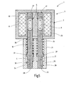
- Fig. 1 is shown in a schematic longitudinal section of an electromagnetic actuator 1 for a camshaft adjustment of an internal combustion engine, not shown.
- the adjusting device 1 is used to adjust the timing of gas exchange valves of the engine designed as a piston engine, not shown, and has a mushroom-shaped housing 21 seen as a whole in section.
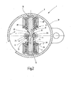
- a coil device 2 which, as in particular the Fig. 2 shows, consists of a first coil 10 and a second coil 11.
- the two electromagnetic coils 10, 11 are arranged diametrically to a longitudinal axis 32 of the adjusting device 1.
- the coils 10, 11 are used to actuate a first actuator 4 and a second actuator 5, which are in the form of plungers 24, 25 and are guided axially displaceably in cylindrical bores in the housing 21.
- a mechanical actuator 7 in the form of a substantially cylindrical bolt is axially displaceable with its respective ends 15 in pile tubes of the coils 10, 11 out.
- the adjusting element 7 is arranged transversely to the actuators 4, 5 and in the in Fig. 1 . 2 shown embodiment between the actuators 4, 5 out. Together with the coils 10, 11 it forms an actuating device 3 for the said actuators 4, 5.
- the actuator 7 has on both sides 13, 14 in the region of the longitudinal axis 32, a shift gate 12, which, as Fig. 2 shows, are formed by part-circular indentations 33 of the outer periphery of the switching element 7. As the Fig. 2 further shows, the part-circular indentations 33 go into less deeply introduced locking edges 34 and corresponding inclined surfaces, so that the in Fig. 2 shown, right actuator 5 is in an extended, second switching position is transferred, in which it is unlocked by the switching element 7 and the left first actuator 4 with the locking edge 34 is engaged, in a corresponding, in both actuators 4, 5 notch existing 35 engages.
- the shift gates 12 thus form a safety device 6 to ensure that only one actuator is unlocked and is moved in the sense of an extended second shift position in which it can make its assignable control tasks in the sense, in particular of cam adjustments.
- the actuators 4, 5 are also guided in the cap 31 in longitudinal guides 36. Further, the actuators 4, 5 of each designed as a compression spring force memory 18, 19, which is supported on each of an axial stop 37 of these actuators and on a part of the housing 21, acted upon in the sense that the respective force memory 18, 19 an extension movement each end-side engaging portion 20 of each actuator 4, 5 allows after its release.
- helical compression springs 38 provide for a mean rest position, which correspond in the embodiment shown an extended shift position and a retracted shift position for each actuator 4, 5.
- the two actuators 4, 5 have a smallest distance a of their outer peripheral surfaces 30, which is smaller than its diameter d. It is in the embodiment shown only about half of the diameter d of the actuators 4, 5 in their end-side engaging portion 20th
- the actuator 5 is moved in its retracted, first switching position by the action of the compression spring 19, while the engagement of the locking edge 34 on the other actuator 4 for the Extension movement is released.
- FIG. 3 also shows the force accumulators 18, 19 which act on the actuators 4, 5, be arranged in the axial direction of the adjusting device 1 between the cap 31 and the adjusting element 7 or the entire actuator 3 and with the aid of plunger-like elements 23 on the attributable actuators 4, 5 act.
- the adjusting element 7 forms an end stop 22 for the respective force accumulator 18, 19.
- both actuators 4, 5 and other actuators, not shown, can also be beneficial, as is the Fig. 4 shows, both actuators 4, 5 and other actuators, not shown, to be arranged on a single side 13 of the control element 7, so that only on one side of the control element 7 shift gates 12 are provided.
- a longitudinal section through a further embodiment of an adjusting device 1 is shown, which is characterized essentially by the embodiments in the Fig. 1 to 4 differs in that at the end regions 27 of the two actuators each have a magnet 8, 9 in a cylindrical, elongated design as a rod permanent magnet, centrally mounted in each actuator 4, 5 stationary.
- the end regions 27 with the permanent magnet extend in the axial region of the coil 10, which surrounds both actuators 4, 5.
- the magnets 8, 9 have mutually arranged poles N, S, so that the actuators 4, 5 in the switching position shown, each corresponding to a first, retracted switching position, attract.
- the same pole arrangement see the Fig. 6 and 7 in front.
- the two force accumulators 18, 19, which are arranged in principle the same way to the actuators 4, 5, are in a prestressed state, as in the rest of the embodiments in the Fig. 6 and 7 the case is.
- the coil 10 has a winding whose polarity is umpolbar, so that when they are energized depending on the current direction selectively in the actuator 4 or in the actuator 5, more precisely on the magnets 8, 9, a repulsive force is formed, which together with the respective pressure force of the respective force accumulator 18, 19 causes an actuator 4 or 5 is extended and its end-side engaging portion 20 emerges from the housing 21.
- the respective other actuator is held by the energization of the coil 10 fixed in the housing 21.
- an actuator such as the actuator 5
- two rectified poles of the magnets 8, 9, here the south pole come into adjacent position, so that an additional repulsive force between the actuators 4, 5 may arise in the axial direction, ie seen in the direction of the longitudinal axis 26 of the actuators 4, 5 acts to the effect that the actuator 5 further tends to be pushed out of the housing 21.
- the energization direction of the coil 10 is changed, then the reverse sequence of the adjusting movement occurs with respect to the two actuators 4, 5 on.
- the structure is chosen such that the permanent magnet arrangement prevents a simultaneous triggering of the respective actuators.
- windings 28, 29 can be energized independently of each other, so that a different polarity arises, which causes the one actuator 4 or the other actuator 5 is brought into an extended, second position. Furthermore, there is also the possibility that one winds two winding wires in parallel and simultaneously in a winding process on the bobbin.
Landscapes
- Engineering & Computer Science (AREA)
- Mechanical Engineering (AREA)
- General Engineering & Computer Science (AREA)
- Physics & Mathematics (AREA)
- Electromagnetism (AREA)
- Power Engineering (AREA)
- Electromagnets (AREA)
- Valve Device For Special Equipments (AREA)
Applications Claiming Priority (1)
| Application Number | Priority Date | Filing Date | Title |
|---|---|---|---|
| DE201010005071 DE102010005071A1 (de) | 2010-01-14 | 2010-01-14 | Elektromagnetische Stellvorrichtung |
Publications (1)
| Publication Number | Publication Date |
|---|---|
| EP2345800A2 true EP2345800A2 (fr) | 2011-07-20 |
Family
ID=43778501
Family Applications (1)
| Application Number | Title | Priority Date | Filing Date |
|---|---|---|---|
| EP20110000137 Withdrawn EP2345800A2 (fr) | 2010-01-14 | 2011-01-11 | Dispositif de réglage électromagnétique |
Country Status (2)
| Country | Link |
|---|---|
| EP (1) | EP2345800A2 (fr) |
| DE (1) | DE102010005071A1 (fr) |
Cited By (3)
| Publication number | Priority date | Publication date | Assignee | Title |
|---|---|---|---|---|
| CN106121764A (zh) * | 2016-07-18 | 2016-11-16 | 杰锋汽车动力系统股份有限公司 | 一种用于可变气门升程系统的凸轮轴调节装置 |
| US20160352168A1 (en) * | 2014-01-29 | 2016-12-01 | Moving Magnet Technologies (Mmt) | Linear electromagnetic actuator comprising two independent moving members |
| WO2017170920A1 (fr) * | 2016-03-31 | 2017-10-05 | 本田技研工業株式会社 | Dispositif de soupape variable |
Families Citing this family (5)
| Publication number | Priority date | Publication date | Assignee | Title |
|---|---|---|---|---|
| DE102012211854B4 (de) * | 2012-07-06 | 2016-03-31 | Schaeffler Technologies AG & Co. KG | Aktorvorrichtung mit Fernübertragung |
| DE102013203138A1 (de) * | 2013-02-26 | 2014-08-28 | Schaeffler Technologies Gmbh & Co. Kg | Aktoreinheit mit translatorischer Stelleinrichtung |
| DE202013101157U1 (de) | 2013-03-18 | 2014-06-24 | Eto Magnetic Gmbh | Elektromagnetische Stellvorrichtung, Verwendung einer solchen elektromagnetischen Stellvorrichtung und System aufweisend eine solche elektromagnetische Stellvorrichtung |
| JP6688132B2 (ja) * | 2016-03-31 | 2020-04-28 | 本田技研工業株式会社 | 可変動弁装置 |
| DE102016107661A1 (de) * | 2016-04-25 | 2017-10-26 | Kendrion (Villingen) Gmbh | Elektromagnetische Stellvorrichtung mit D-förmiger Spule für 2-Pin-Aktor |
Citations (3)
| Publication number | Priority date | Publication date | Assignee | Title |
|---|---|---|---|---|
| WO2003021612A1 (fr) | 2001-09-01 | 2003-03-13 | Ina-Schaeffler Kg | Dispositif de reglage electromagnetique |
| WO2008155119A1 (fr) | 2007-06-19 | 2008-12-24 | Eto Magnetic Gmbh | Dispositif de réglage électromagnétique |
| WO2009056221A1 (fr) | 2007-11-02 | 2009-05-07 | Daimler Ag | Mécanisme de distribution |
Family Cites Families (3)
| Publication number | Priority date | Publication date | Assignee | Title |
|---|---|---|---|---|
| AU1728500A (en) * | 1998-11-20 | 2000-06-13 | Mas-Hamilton Group, Inc. | Autosecuring solenoid |
| DE102008029324B4 (de) * | 2008-06-20 | 2024-01-11 | Mercedes-Benz Group AG | Ventiltriebvorrichtung |
| DE102008060166A1 (de) * | 2008-11-27 | 2010-06-02 | Dr.Ing.H.C.F.Porsche Aktiengesellschaft | Ventiltrieb für Gaswechselventile einer Brennkraftmaschine |
-
2010
- 2010-01-14 DE DE201010005071 patent/DE102010005071A1/de not_active Withdrawn
-
2011
- 2011-01-11 EP EP20110000137 patent/EP2345800A2/fr not_active Withdrawn
Patent Citations (3)
| Publication number | Priority date | Publication date | Assignee | Title |
|---|---|---|---|---|
| WO2003021612A1 (fr) | 2001-09-01 | 2003-03-13 | Ina-Schaeffler Kg | Dispositif de reglage electromagnetique |
| WO2008155119A1 (fr) | 2007-06-19 | 2008-12-24 | Eto Magnetic Gmbh | Dispositif de réglage électromagnétique |
| WO2009056221A1 (fr) | 2007-11-02 | 2009-05-07 | Daimler Ag | Mécanisme de distribution |
Cited By (6)
| Publication number | Priority date | Publication date | Assignee | Title |
|---|---|---|---|---|
| US20160352168A1 (en) * | 2014-01-29 | 2016-12-01 | Moving Magnet Technologies (Mmt) | Linear electromagnetic actuator comprising two independent moving members |
| US10389197B2 (en) * | 2014-01-29 | 2019-08-20 | Moving Magnet Technologies (Mmt) | Linear electromagnetic actuator comprising two independent moving members |
| WO2017170920A1 (fr) * | 2016-03-31 | 2017-10-05 | 本田技研工業株式会社 | Dispositif de soupape variable |
| JP2017180398A (ja) * | 2016-03-31 | 2017-10-05 | 本田技研工業株式会社 | 可変動弁装置 |
| US10480357B2 (en) | 2016-03-31 | 2019-11-19 | Honda Motor Co., Ltd. | Variable valve train |
| CN106121764A (zh) * | 2016-07-18 | 2016-11-16 | 杰锋汽车动力系统股份有限公司 | 一种用于可变气门升程系统的凸轮轴调节装置 |
Also Published As
| Publication number | Publication date |
|---|---|
| DE102010005071A1 (de) | 2011-07-21 |
Similar Documents
| Publication | Publication Date | Title |
|---|---|---|
| EP2823203B1 (fr) | Unité de verrouillage, en particulier pour un frein de stationnement d'une boîte de vitesses automatique | |
| EP2345800A2 (fr) | Dispositif de réglage électromagnétique | |
| EP2082120B1 (fr) | Dispositif de réglage de l'arbre à came d'un moteur à combustion interne | |
| EP2401479B1 (fr) | Dispositif de réglage électromagnétique | |
| EP2486575B1 (fr) | Actionneur pour moteur à combustion interne | |
| EP2883233B1 (fr) | Appareil de réglage électromagnétique bistable, groupe de construction d'armature et dispositif de réglage d'arbre à cames | |
| WO2008052884A1 (fr) | Dispositif de réglage | |
| EP3464968B1 (fr) | Dispositif soupape électromagnétique et système | |
| EP2582928A1 (fr) | Dispositif actionneur destiné au réglage d'un système de came coulissante | |
| DE102016210976A1 (de) | Ventiltrieb für eine Brennkraftmaschine | |
| DE102009030375A1 (de) | Elektromagnetische Stellvorrichtung | |
| EP3191695A1 (fr) | Dispositif de réglage électromagnétique | |
| DE102019104786A1 (de) | Variabler Ventiltrieb einer Hubkolbenbrennkraftmaschine | |
| EP3443571B1 (fr) | Dispositif de réglage électromagnétique monostable sans courant et utilisation d'un tel dispositif | |
| EP2775485B1 (fr) | Dispositif d'actionnement électromagnétique, notamment pour le réglage de l'arbre à cames d'un moteur à combustion interne | |
| EP0748416B1 (fr) | Commande électromagnétique d'une soupape dans un moteur a combustion interne | |
| EP2378167B1 (fr) | Unité de verrouillage | |
| EP2443373B1 (fr) | Electrovanne | |
| DE102014216274A1 (de) | Aktuator mit zumindest einer stabilen Schaltlage | |
| DE19937947C2 (de) | Vorrichtung zum Schalten einer elektrischen Verbindung in Abhängigkeit des Zustandes einer Schutzeinrichtung | |
| DE202010010093U1 (de) | Magnetsystem | |
| EP3161282B1 (fr) | Dispositif de selection de came pour moteur à combustion interne | |
| DE102018111195A1 (de) | Hubmagnet | |
| EP3449104B1 (fr) | Dispositif de commande électromagnétique à bobine en forme de d pour actionneur à deux broches | |
| DE102016210975A1 (de) | Ventiltrieb für eine Brennkraftmaschine |
Legal Events
| Date | Code | Title | Description |
|---|---|---|---|
| PUAI | Public reference made under article 153(3) epc to a published international application that has entered the european phase |
Free format text: ORIGINAL CODE: 0009012 |
|
| AK | Designated contracting states |
Kind code of ref document: A2 Designated state(s): AL AT BE BG CH CY CZ DE DK EE ES FI FR GB GR HR HU IE IS IT LI LT LU LV MC MK MT NL NO PL PT RO RS SE SI SK SM TR |
|
| AX | Request for extension of the european patent |
Extension state: BA ME |
|
| STAA | Information on the status of an ep patent application or granted ep patent |
Free format text: STATUS: THE APPLICATION IS DEEMED TO BE WITHDRAWN |
|
| 18D | Application deemed to be withdrawn |
Effective date: 20130801 |