EP2345808A2 - Steuerung für Leerlaufstoppsystem - Google Patents
Steuerung für Leerlaufstoppsystem Download PDFInfo
- Publication number
- EP2345808A2 EP2345808A2 EP11150887A EP11150887A EP2345808A2 EP 2345808 A2 EP2345808 A2 EP 2345808A2 EP 11150887 A EP11150887 A EP 11150887A EP 11150887 A EP11150887 A EP 11150887A EP 2345808 A2 EP2345808 A2 EP 2345808A2
- Authority
- EP
- European Patent Office
- Prior art keywords
- engine
- combustion recovery
- combustion
- fuel
- request
- Prior art date
- Legal status (The legal status is an assumption and is not a legal conclusion. Google has not performed a legal analysis and makes no representation as to the accuracy of the status listed.)
- Ceased
Links
Images


Classifications
-
- F—MECHANICAL ENGINEERING; LIGHTING; HEATING; WEAPONS; BLASTING
- F02—COMBUSTION ENGINES; HOT-GAS OR COMBUSTION-PRODUCT ENGINE PLANTS
- F02N—STARTING OF COMBUSTION ENGINES; STARTING AIDS FOR SUCH ENGINES, NOT OTHERWISE PROVIDED FOR
- F02N11/00—Starting of engines by means of electric motors
- F02N11/08—Circuits specially adapted for starting of engines
- F02N11/0814—Circuits specially adapted for starting of engines comprising means for controlling automatic idle-start-stop
- F02N11/0844—Circuits specially adapted for starting of engines comprising means for controlling automatic idle-start-stop with means for restarting the engine directly after an engine stop request, e.g. caused by change of driver mind
-
- F—MECHANICAL ENGINEERING; LIGHTING; HEATING; WEAPONS; BLASTING
- F02—COMBUSTION ENGINES; HOT-GAS OR COMBUSTION-PRODUCT ENGINE PLANTS
- F02D—CONTROLLING COMBUSTION ENGINES
- F02D35/00—Controlling engines, dependent on conditions exterior or interior to engines, not otherwise provided for
- F02D35/02—Controlling engines, dependent on conditions exterior or interior to engines, not otherwise provided for on interior conditions
- F02D35/023—Controlling engines, dependent on conditions exterior or interior to engines, not otherwise provided for on interior conditions by determining the cylinder pressure
-
- F—MECHANICAL ENGINEERING; LIGHTING; HEATING; WEAPONS; BLASTING
- F02—COMBUSTION ENGINES; HOT-GAS OR COMBUSTION-PRODUCT ENGINE PLANTS
- F02N—STARTING OF COMBUSTION ENGINES; STARTING AIDS FOR SUCH ENGINES, NOT OTHERWISE PROVIDED FOR
- F02N11/00—Starting of engines by means of electric motors
- F02N11/08—Circuits specially adapted for starting of engines
- F02N11/0848—Circuits specially adapted for starting of engines with means for detecting successful engine start, e.g. to stop starter actuation
-
- F—MECHANICAL ENGINEERING; LIGHTING; HEATING; WEAPONS; BLASTING
- F02—COMBUSTION ENGINES; HOT-GAS OR COMBUSTION-PRODUCT ENGINE PLANTS
- F02N—STARTING OF COMBUSTION ENGINES; STARTING AIDS FOR SUCH ENGINES, NOT OTHERWISE PROVIDED FOR
- F02N11/00—Starting of engines by means of electric motors
- F02N11/08—Circuits specially adapted for starting of engines
- F02N11/0851—Circuits specially adapted for starting of engines characterised by means for controlling the engagement or disengagement between engine and starter, e.g. meshing of pinion and engine gear
- F02N11/0855—Circuits specially adapted for starting of engines characterised by means for controlling the engagement or disengagement between engine and starter, e.g. meshing of pinion and engine gear during engine shutdown or after engine stop before start command, e.g. pre-engagement of pinion
-
- F—MECHANICAL ENGINEERING; LIGHTING; HEATING; WEAPONS; BLASTING
- F02—COMBUSTION ENGINES; HOT-GAS OR COMBUSTION-PRODUCT ENGINE PLANTS
- F02N—STARTING OF COMBUSTION ENGINES; STARTING AIDS FOR SUCH ENGINES, NOT OTHERWISE PROVIDED FOR
- F02N99/00—Subject matter not provided for in the other groups of this subclass
- F02N99/002—Starting combustion engines by ignition means
- F02N99/006—Providing a combustible mixture inside the cylinder
-
- F—MECHANICAL ENGINEERING; LIGHTING; HEATING; WEAPONS; BLASTING
- F02—COMBUSTION ENGINES; HOT-GAS OR COMBUSTION-PRODUCT ENGINE PLANTS
- F02D—CONTROLLING COMBUSTION ENGINES
- F02D2200/00—Input parameters for engine control
- F02D2200/02—Input parameters for engine control the parameters being related to the engine
- F02D2200/10—Parameters related to the engine output, e.g. engine torque or engine speed
- F02D2200/1012—Engine speed gradient
-
- F—MECHANICAL ENGINEERING; LIGHTING; HEATING; WEAPONS; BLASTING
- F02—COMBUSTION ENGINES; HOT-GAS OR COMBUSTION-PRODUCT ENGINE PLANTS
- F02N—STARTING OF COMBUSTION ENGINES; STARTING AIDS FOR SUCH ENGINES, NOT OTHERWISE PROVIDED FOR
- F02N2200/00—Parameters used for control of starting apparatus
- F02N2200/02—Parameters used for control of starting apparatus said parameters being related to the engine
- F02N2200/022—Engine speed
-
- F—MECHANICAL ENGINEERING; LIGHTING; HEATING; WEAPONS; BLASTING
- F02—COMBUSTION ENGINES; HOT-GAS OR COMBUSTION-PRODUCT ENGINE PLANTS
- F02N—STARTING OF COMBUSTION ENGINES; STARTING AIDS FOR SUCH ENGINES, NOT OTHERWISE PROVIDED FOR
- F02N2300/00—Control related aspects of engine starting
- F02N2300/20—Control related aspects of engine starting characterised by the control method
- F02N2300/2002—Control related aspects of engine starting characterised by the control method using different starting modes, methods, or actuators depending on circumstances, e.g. engine temperature or component wear
-
- Y—GENERAL TAGGING OF NEW TECHNOLOGICAL DEVELOPMENTS; GENERAL TAGGING OF CROSS-SECTIONAL TECHNOLOGIES SPANNING OVER SEVERAL SECTIONS OF THE IPC; TECHNICAL SUBJECTS COVERED BY FORMER USPC CROSS-REFERENCE ART COLLECTIONS [XRACs] AND DIGESTS
- Y02—TECHNOLOGIES OR APPLICATIONS FOR MITIGATION OR ADAPTATION AGAINST CLIMATE CHANGE
- Y02T—CLIMATE CHANGE MITIGATION TECHNOLOGIES RELATED TO TRANSPORTATION
- Y02T10/00—Road transport of goods or passengers
- Y02T10/10—Internal combustion engine [ICE] based vehicles
- Y02T10/40—Engine management systems
Definitions
- the request for re-start of the engine occurs during an engine inertia revolution period after the fuel to be supplied to the engine is cut off by the request for idle stop which occurs when the aforementioned predetermined conditions are established until the crankshaft of the engine stops revolution, re-starting the engine as quickly as possible is requested.
- the behavior of engine revolution reduces to the region requiring the assist by the starter, the control of re-starting the engine by driving the starter is implemented, and the operations of re-starting the engine by combustion and re-starting the engine by driving the starter overlap.
- the pinion gear collides with the ring gear at the engine side, and the collision torque becomes large, whereby there arise the problems of wear of the ring gear and the pinion gear at the time of connection, and reduction in durability. Further, since the collision torque becomes large, there arises the problem that a collision sound of the ring gear and the pinion gear, and a mesh sound which occurs at the instant of connection become large.
- the engine in the configuration which performs idle stop, the engine can be smoothly re-started after a request for change of mind occurs. Further, durability, wear resistance, and quietness of the starter system can be improved.
- FIG. 1 is a functional block diagram of an idle stop system.
- a starter main body 101 is configured by a starter motor 101a, a magnet switch 101b, a shift lever 101c, a pinion clutch 101d, a pinion gear 101e and the like.
- the starter motor 101a and the magnet switch 101b are driven by controlling power supply relays (of a starter motor relay 104 or a pinion relay 105) which are independent from each other, based on output from an ECU 103 (Engine Control Unit).
- the starter motor 101a and the pinion gear 101e are coaxially connected, and when the starter motor 101a rotates, the pinion gear 101e also rotates.
- the magnet switch 101b is energized, the shift lever 101c is pushed out, and the pinion gear 101e is connected to a ring gear 106 which is included by an engine.
- an engine combustion recovery function 103d When a start request is made, a so-called request of change of mind is made before the crankshaft of the engine stops after the idle stop permission judgment is performed, various kinds of controls for combustion recovery including re-start of fuel injection are implemented by an engine combustion recovery function 103d. Further, in a starter control block 103b, control of a starter motor relay 104 and a pinion relay 105 is implemented. The combustion recovery function 103d controls at least a fuel amount to be supplied to the engine, a fuel supply timing and an ignition timing to recover the combustion.
- FIG. 2 is one embodiment according to the present invention.
- the control is implemented at constant intervals (for example, every 10 ms).
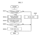
- S201 a possibility judgment of implementation of idle stop is performed from the information of various sensors and the like illustrated in FIG. 1 .
- the flow proceeds to S202, whereas when it is not established, the flow ends.
- S202 in order to stop the engine, fuel cut control for cutting off the fuel to be supplied to the engine is implemented.
- the crankshaft of the engine is brought into the state of inertia revolution, becomes gradually slow in the revolution speed due to the influence of the resistance of friction and the like, and finally stops.
- S203 it is judged whether or not a request for re-start of the engine (request for change of mind) occurs during the inertia revolution of the engine (the crankshaft).
- idle stop permission judgment is implemented from the information of various sensors such as the brake SW and the vehicle speed sensor in the idle stop permission judgment block 103a, whereby presence or absence of a request for the re-start of the engine during inertia revolution is judged.
- the flow proceeds to S204.
- the condition is not established, the flow proceeds to S205, and the conventional idle stop control is implemented.
- various kinds of controls for combustion recovery including re-start of fuel injection are implemented by the engine combustion recovery function.
- S206 the engine state after the controls by the combustion recovery function is implemented is judged.
- S207 from the judgment result of S206, selection of starter drive control is performed, and the selected starter drive control is implemented in S208.
- FIG. 3 is a flowchart of one embodiment according to the present invention.
- the present flow is implemented at constant intervals (for example, every 10 ms).
- the following problem can be solved according to the present embodiment. More specifically, even if fuel supply is re-started, and re-start of the engine by combustion is implemented, the engine speed does not immediately increases, and it is necessary to wait for a certain time to elapse. This is because when a port fuel injection (PFI) engine injecting a fuel into the intake port is taken as an example, a time is required from the intake stroke in which fuel injection is performed to the expansion stroke in which the combustion torque can be obtained in the cylinder that performs fuel injection first from re-start of fuel supply. There is naturally the problem that during this time period, reduction in the engine revolution is unavoidable. The same problem also exists in a direct-injection type engine.
- PFI port fuel injection
- the aforementioned problems can be solved by performing the possibility judgment of combustion recovery by allowing for reduction in the engine speed at the initial stage of combustion recovery by judging whether it is possible or difficult (or impossible) that the control of combustion recovery is implemented.
- FIG. 4 is a flowchart of one embodiment according to the present invention.
- the present flow is implemented at constant intervals (for example, 10 ms).
- the magnet switch is energized, whereby the pinion gear is connected to the ring gear included by the engine, and re-start of the engine by starter drive can be performed.
- re-start of the engine by starter drive is implemented when re-start of the engine by combustion (combustion recovery) is difficult. Therefore, re-start of the engine can be performed without engine stop, the re-start times can become shorter than ever before, and smooth re-start of the engine can be performed.
- FIG. 5 is a flowchart of one embodiment according to the present invention.
- the present flow is implemented at constant intervals (for example, 10 ms).
- the pinion gear and the ring gear are connected in the state in which the difference between the engine speed and the pinion revolution speed is small, whereby re-start of the engine can be performed, the collision torque at the time of connecting the pinion gear and the ring gear is lessened, the collision sound and the mesh sound are reduced, and wear of the ring gear and the pinion gear can be lessened.
- a pinion revolution angular acceleration ⁇ Np is calculated. In this calculation method, calculation is simply made as in S612. Thereafter, in S614, a pinion angular acceleration direction is judged. If ⁇ Np is smaller than zero, the flow proceeds to S615, where it is determined as negative angular acceleration judgment, and a pinion acceleration direction judgment flag FDNP is set as one. Further, if ⁇ Np is larger than zero, the flow proceeds to S616, where it is judged as a positive acceleration, and the pinion acceleration direction judgment flag FDNP is set as zero. In S617, an engine angular acceleration direction is judged.
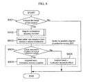
- FIG. 8 is a flowchart of one embodiment according to the present invention.
- the present flow is implemented at constant intervals (for example, 10 ms).
- S801 presence or absence of the request for change of mind is judged, and this indicates equivalence to implementing fuel cut control (S202) after the idle stop permission judgment in FIG. 2 is established (S201) and performing judgment of whether or not the request for the re-start of the engine (or for the start of the vehicle) occurs during inertia revolution of the engine (S203).
- S202 fuel cut control
- S201 idle stop permission judgment in FIG. 2
- S203 performing judgment of whether or not the request for the re-start of the engine (or for the start of the vehicle) occurs during inertia revolution of the engine
- the starter motor energizing time TIMCOUNT is incremented at constant intervals (in this case, every 10 ms is assumed though not especially specified), and in S909, it is determined whether the energizing time TIMCOUNT of the starter motor is not less than the required energizing time RQTIM which is set in advance or calculated by predetermined calculation.
- the flow proceeds to S910, and when the condition of S909 is not established, the flow returns to S907, and energization of the starter motor is continued until the condition of S909 is established.
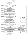
- the flow proceeds to S1007.
- the flow proceeds to S1008, and the conventional idle stop control is implemented.
- S1007 the engine speed Ne2 at the time of occurrence of change of mind is read, and in S1009, a deceleration ⁇ Ne of engine revolution is calculated.
- the difference between the engine speed Ne4 at the time of start of fuel cut and the engine speed Ne2 at the time point when change of mind occurs is divided by the timer counter TIMCOUNT, and thereby, the inclination of the deceleration is obtained.
- a different method may be used.
- S1010 the possibility judgment of combustion recovery using the deceleration ⁇ Ne of engine revolution is performed.
- the engine speed Ne3 at the time point T1116 is not less than the combustion recovery judgment reference value NeJDG (1108), or the engine speed Ne3 at the time point T1116 increases to the second combustion recovery judgment reference value NeJDG2 (1109) or more from the engine speed Ne2 (1107) at the time point when the request for change of mind occurs, and therefore, the result of the possibility judgment of combustion recovery is the judgment that combustion recovery is possible. Consequently, according to one embodiment according to the present invention, starter control (energization of the magnet switch (1105) and the starter motor (1106)) of T116 and thereafter is prohibited. The description of the present operation only shows one example in idle stop, and the vehicle operation state which achieves idle stop is not limited to this.
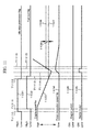
- the idle stop permission flag (1201) becomes low due to a request for change of mind, and after a predetermined delay time elapses from T1213, control necessary for combustion recovery such as fuel injection is implemented by the engine combustion recovery function at T1214, and engine speed (1203) originally increases, but in the present drawing, the engine is in the state in which favorable combustion recovery cannot be performed, and the engine speed (1203) continues to be decreased.
- the engine speed Ne3 after the engine combustion recovery function is implemented is read (Timing of T1215 is omitted since it is already described.).
- the vehicle controller of one embodiment according to the present invention performs the possibility judgment of combustion recovery based on the engine speed Ne3 at the time point T1215.
- the timing (T1216) of energizing the starter motor and the magnet switch is described by using the method of comparing the engine speed (1203) and the starter drive permission revolution speed STJDG (1208), but the method does not have to be specially limited to this method, and the method of energizing the starter motor (1206) and the magnet switch (1207) after a predetermined time elapses from the time point (T1213) when a request for change of mind occurs, the time point (T1214) when the fuel cut is started, and the like may be used. Further, the description of the present operation only shows one example in idle stop, and the vehicle operation state which achieves idle stop is not limited to this.
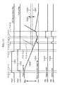
- Reference numeral 1301 designates an idle stop permission condition flag, which becomes high when permission of implementation of idle stop is judged based on information and the like of various sensors illustrated in FIG. 1 and idle stop is permitted, and becomes low when idle stop is prohibited.
- Reference numeral 1302 designates a fuel cut flag, which becomes high during implementation of fuel cut, and becomes low when fuel cut is not performed.
- Reference numeral 1303 designates an engine speed
- reference numeral 1304 designates a pinion revolution speed.
- reference numeral 1305 designates an energization state of the magnet switch
- reference numeral 1306 designates an energization state to the starter motor.
- Reference numeral 1307 designates an engine speed Ne2 at the time of change of mind
- reference numeral 1308 designates a combustion recovery judgment reference value NeJDG
- reference numeral 1309 designates a second combustion recovery judgment reference value NeJDG2.
- the idle stop permission flag (1301) becomes low due to a request for change of mind, and after a predetermined delay time elapses from T1312, control necessary for combustion recovery such as fuel injection is implemented by the engine combustion recovery function at T1313, and engine speed (1303) originally increases, but in the present drawing, the engine is in the state in which favorable combustion recovery cannot be performed, and the engine speed (1303) continues to be reduced.
- the engine speed Ne3 after the engine combustion recovery function is implemented is read (Description of the timing of T1314 is omitted since it is already described.).
- the vehicle controller of one embodiment according to the present invention performs the possibility judgment of combustion recovery based on the engine speed Ne3 at the time point T1314.
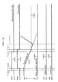
- Reference numeral 1401 designates an idle stop permission condition flag, which becomes high when permission of implementation of idle stop is judged based on information and the like of various sensors illustrated in FIG. 1 , and idle stop is permitted, and becomes low when idle stop is prohibited.
- Reference numeral 1402 designates a fuel cut flag, which becomes high during implementation of fuel cut, and becomes low when fuel cut is not performed.
- Reference numeral 1403 designates an engine speed
- reference numeral 1404 designates a pinion revolution speed.
- reference numeral 1405 designates an energization state of the magnet switch
- reference numeral 1406 designates an energization state to the starter motor.
- Reference numeral 1407 designates a combustion recovery judgment reference value NeJDG.
- the engine is in the state in which combustion recovery is possible, and as for starter drive, starter drive at T1410 when the possibility judgment of combustion recovery is implemented and thereafter is prohibited, and therefore, both the energization (1405) of the magnet switch and the energization (1406) of the starter motor are stopped.
- the description of the present operation only shows one example in idle stop, and the vehicle operation state which achieves idle stop is not limited to this.
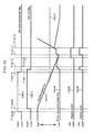
- FIG. 15 is a timing chart using a vehicle controller of one embodiment according to the present invention.
- the idle stop permission flag (1601) becomes high, a predetermined delay time elapses, fuel cut is implemented, and the fuel cut flag (1602) becomes high (T1609).
- the engine is brought into the state of inertial revolution and starts to be gradually low in speed (1603).
- the idle stop permission flag (1601) becomes low due to a request for change of mind.
- the vehicle controller of one embodiment according to the present invention performs the possibility judgment of combustion recovery based on the engine speed (1603) at the time point T1610 when the request for change of mind occurs, or the engine deceleration up to T1610.
Landscapes
- Engineering & Computer Science (AREA)
- Chemical & Material Sciences (AREA)
- Combustion & Propulsion (AREA)
- Mechanical Engineering (AREA)
- General Engineering & Computer Science (AREA)
- Control Of Vehicle Engines Or Engines For Specific Uses (AREA)
- Electrical Control Of Air Or Fuel Supplied To Internal-Combustion Engine (AREA)
Applications Claiming Priority (1)
| Application Number | Priority Date | Filing Date | Title |
|---|---|---|---|
| JP2010005417A JP5094889B2 (ja) | 2010-01-14 | 2010-01-14 | 燃料消費節約型車両制御装置 |
Publications (2)
| Publication Number | Publication Date |
|---|---|
| EP2345808A2 true EP2345808A2 (de) | 2011-07-20 |
| EP2345808A3 EP2345808A3 (de) | 2015-10-28 |
Family
ID=43855959
Family Applications (1)
| Application Number | Title | Priority Date | Filing Date |
|---|---|---|---|
| EP11150887.5A Ceased EP2345808A3 (de) | 2010-01-14 | 2011-01-13 | Steuerung für Leerlaufstoppsystem |
Country Status (4)
| Country | Link |
|---|---|
| US (1) | US20110172900A1 (de) |
| EP (1) | EP2345808A3 (de) |
| JP (1) | JP5094889B2 (de) |
| CN (1) | CN102128099B (de) |
Cited By (2)
| Publication number | Priority date | Publication date | Assignee | Title |
|---|---|---|---|---|
| CN104213991A (zh) * | 2013-05-31 | 2014-12-17 | 三菱自动车工业株式会社 | 引擎控制单元 |
| EP2685084A4 (de) * | 2011-03-11 | 2015-02-11 | Hitachi Automotive Systems Ltd | Startvorrichtung für einen fahrzeugmotor |
Families Citing this family (9)
| Publication number | Priority date | Publication date | Assignee | Title |
|---|---|---|---|---|
| JP5656013B2 (ja) * | 2010-01-11 | 2015-01-21 | 株式会社デンソー | エンジン自動停止始動制御装置 |
| JP5025752B2 (ja) * | 2010-03-30 | 2012-09-12 | 三菱電機株式会社 | 内燃機関の自動停止・再始動装置 |
| US9102334B2 (en) | 2012-10-29 | 2015-08-11 | Deere & Company | Methods and apparatus to control motors |
| JP2015140688A (ja) * | 2014-01-27 | 2015-08-03 | 日立オートモティブシステムズ株式会社 | アイドルストップシステムの制御装置 |
| JP6863216B2 (ja) * | 2017-10-12 | 2021-04-21 | トヨタ自動車株式会社 | 内燃機関の制御装置 |
| JP7156830B2 (ja) * | 2018-06-14 | 2022-10-19 | 株式会社Subaru | 車両の制御装置 |
| GB2580096B (en) * | 2018-12-21 | 2021-10-27 | Jaguar Land Rover Ltd | Controller and method for operating starter motor |
| KR102751053B1 (ko) * | 2019-07-01 | 2025-01-09 | 현대자동차주식회사 | 차량의 엔진 재시동제어 방법 |
| KR102864453B1 (ko) * | 2024-04-29 | 2025-09-25 | 주식회사 현대케피코 | 48v 시스템 차량의 체인지 오브 마인드 상황 대응을 위한 엔진스테이트 운영 방법 |
Citations (1)
| Publication number | Priority date | Publication date | Assignee | Title |
|---|---|---|---|---|
| JP4214401B2 (ja) | 2004-05-18 | 2009-01-28 | 株式会社デンソー | エンジン自動停止再始動装置 |
Family Cites Families (18)
| Publication number | Priority date | Publication date | Assignee | Title |
|---|---|---|---|---|
| US3769950A (en) * | 1971-11-29 | 1973-11-06 | A Braun | Free piston engine starting apparatus |
| JPH0657881B2 (ja) * | 1990-11-26 | 1994-08-03 | 儀雄 伊藤 | ミニ着物の作成方法 |
| JP3821202B2 (ja) * | 2000-06-16 | 2006-09-13 | 三菱自動車工業株式会社 | 筒内噴射型内燃機関の始動装置 |
| JP4211208B2 (ja) * | 2000-08-23 | 2009-01-21 | トヨタ自動車株式会社 | 燃料消費節約型自動車 |
| US7134414B2 (en) * | 2003-02-10 | 2006-11-14 | Robert Bosch Gmbh | Method and device for starting an internal combustion engine |
| JP4466437B2 (ja) * | 2005-03-31 | 2010-05-26 | マツダ株式会社 | 車両のエンジン始動装置 |
| JP4466443B2 (ja) * | 2005-03-31 | 2010-05-26 | マツダ株式会社 | 車両のエンジン始動装置 |
| JP2006299997A (ja) * | 2005-04-22 | 2006-11-02 | Toyota Motor Corp | 内燃機関の始動装置 |
| DE102005049092B4 (de) * | 2005-10-13 | 2016-06-02 | Robert Bosch Gmbh | Verfahren zum Einspuren des Starterritzels eines Starters in den Anlasserzahnkreis einer Brennkraftmaschine beim Auslaufen der Brennkraftmaschine |
| JP4830925B2 (ja) * | 2007-03-14 | 2011-12-07 | マツダ株式会社 | 手動変速機付き車両用エンジンの自動停止装置 |
| EP2322784A4 (de) * | 2008-05-12 | 2015-08-19 | Toyota Motor Co Ltd | Stopp-/start-steuervorrichtung für einen verbrennungsmotor |
| JP5007839B2 (ja) * | 2008-09-02 | 2012-08-22 | 株式会社デンソー | エンジン自動停止始動制御装置 |
| US8370051B2 (en) * | 2009-01-05 | 2013-02-05 | Ford Global Technologies, Llc | Methods and systems for assisted direct start control |
| JP2010229882A (ja) * | 2009-03-27 | 2010-10-14 | Hitachi Automotive Systems Ltd | 車両制御装置およびアイドルストップシステム |
| JP5316369B2 (ja) * | 2009-10-27 | 2013-10-16 | 三菱電機株式会社 | エンジン始動装置 |
| JP5450311B2 (ja) * | 2010-08-04 | 2014-03-26 | 日立オートモティブシステムズ株式会社 | アイドルストップ制御方法および制御装置 |
| JP5189154B2 (ja) * | 2010-10-28 | 2013-04-24 | 三菱電機株式会社 | エンジン自動停止再始動装置 |
| GB2489499B (en) * | 2011-03-31 | 2016-08-24 | Ford Global Tech Llc | A method and system for controlling an engine |
-
2010
- 2010-01-14 JP JP2010005417A patent/JP5094889B2/ja not_active Expired - Fee Related
-
2011
- 2011-01-11 US US13/004,618 patent/US20110172900A1/en not_active Abandoned
- 2011-01-13 EP EP11150887.5A patent/EP2345808A3/de not_active Ceased
- 2011-01-14 CN CN201110021226.6A patent/CN102128099B/zh not_active Expired - Fee Related
Patent Citations (1)
| Publication number | Priority date | Publication date | Assignee | Title |
|---|---|---|---|---|
| JP4214401B2 (ja) | 2004-05-18 | 2009-01-28 | 株式会社デンソー | エンジン自動停止再始動装置 |
Cited By (4)
| Publication number | Priority date | Publication date | Assignee | Title |
|---|---|---|---|---|
| EP2685084A4 (de) * | 2011-03-11 | 2015-02-11 | Hitachi Automotive Systems Ltd | Startvorrichtung für einen fahrzeugmotor |
| CN104213991A (zh) * | 2013-05-31 | 2014-12-17 | 三菱自动车工业株式会社 | 引擎控制单元 |
| EP2808535A3 (de) * | 2013-05-31 | 2015-03-11 | Mitsubishi Jidosha Kogyo K.K. | Motorsteuerungseinheit |
| CN104213991B (zh) * | 2013-05-31 | 2018-03-20 | 三菱自动车工业株式会社 | 引擎控制单元 |
Also Published As
| Publication number | Publication date |
|---|---|
| JP5094889B2 (ja) | 2012-12-12 |
| EP2345808A3 (de) | 2015-10-28 |
| CN102128099B (zh) | 2015-05-06 |
| JP2011144740A (ja) | 2011-07-28 |
| CN102128099A (zh) | 2011-07-20 |
| US20110172900A1 (en) | 2011-07-14 |
Similar Documents
| Publication | Publication Date | Title |
|---|---|---|
| EP2345808A2 (de) | Steuerung für Leerlaufstoppsystem | |
| CN102828878B (zh) | 车载发动机的起动控制装置 | |
| JP4835774B2 (ja) | エンジン停止始動制御装置 | |
| CN102374092B (zh) | 空转停止控制方法及控制装置 | |
| CN102472232B (zh) | 发动机起动装置 | |
| EP2233731A2 (de) | Fahrzeugsteuervorrichtung und Leerlaufsystem | |
| US8936531B2 (en) | Stop-in-park control for micro-hybrid vehicles | |
| JP2012237218A (ja) | 内燃機関の自動停止再始動装置 | |
| CN102597490B (zh) | 发动机起动装置 | |
| JP2011220164A (ja) | エンジン自動停止始動制御装置 | |
| JP5429199B2 (ja) | エンジン停止始動制御装置 | |
| JP5413325B2 (ja) | エンジン停止始動制御装置 | |
| JP6037436B2 (ja) | エンジン始動装置および始動方法 | |
| JP5288070B2 (ja) | エンジンの制御装置および制御方法、ならびに車両 | |
| JP5548102B2 (ja) | 車両の制御装置 | |
| JP6076485B2 (ja) | エンジン自動停止再始動装置 | |
| JP5808298B2 (ja) | 内燃機関のバッテリ状態判別装置 | |
| JP5836072B2 (ja) | 内燃機関停止装置 | |
| EP2006519B1 (de) | Steuerung für ein Fahrzeug | |
| CN103429885B (zh) | 起动机的控制装置、控制方法和车辆 | |
| JP5949531B2 (ja) | 車両の始動制御装置 | |
| JP6203653B2 (ja) | アイドルストップシステムの制御装置 | |
| JP2017020404A (ja) | エンジン始動制御装置 | |
| JP2015140688A (ja) | アイドルストップシステムの制御装置 |
Legal Events
| Date | Code | Title | Description |
|---|---|---|---|
| PUAI | Public reference made under article 153(3) epc to a published international application that has entered the european phase |
Free format text: ORIGINAL CODE: 0009012 |
|
| 17P | Request for examination filed |
Effective date: 20110527 |
|
| AK | Designated contracting states |
Kind code of ref document: A2 Designated state(s): AL AT BE BG CH CY CZ DE DK EE ES FI FR GB GR HR HU IE IS IT LI LT LU LV MC MK MT NL NO PL PT RO RS SE SI SK SM TR |
|
| AX | Request for extension of the european patent |
Extension state: BA ME |
|
| PUAL | Search report despatched |
Free format text: ORIGINAL CODE: 0009013 |
|
| AK | Designated contracting states |
Kind code of ref document: A3 Designated state(s): AL AT BE BG CH CY CZ DE DK EE ES FI FR GB GR HR HU IE IS IT LI LT LU LV MC MK MT NL NO PL PT RO RS SE SI SK SM TR |
|
| AX | Request for extension of the european patent |
Extension state: BA ME |
|
| RIC1 | Information provided on ipc code assigned before grant |
Ipc: F02N 99/00 20100101AFI20150921BHEP Ipc: F02N 11/08 20060101ALI20150921BHEP |
|
| STAA | Information on the status of an ep patent application or granted ep patent |
Free format text: STATUS: EXAMINATION IS IN PROGRESS |
|
| 17Q | First examination report despatched |
Effective date: 20180529 |
|
| STAA | Information on the status of an ep patent application or granted ep patent |
Free format text: STATUS: THE APPLICATION HAS BEEN REFUSED |
|
| 18R | Application refused |
Effective date: 20201129 |