EP2345809A1 - Génération d'énergie hydro-électrique - Google Patents
Génération d'énergie hydro-électrique Download PDFInfo
- Publication number
- EP2345809A1 EP2345809A1 EP10151095A EP10151095A EP2345809A1 EP 2345809 A1 EP2345809 A1 EP 2345809A1 EP 10151095 A EP10151095 A EP 10151095A EP 10151095 A EP10151095 A EP 10151095A EP 2345809 A1 EP2345809 A1 EP 2345809A1
- Authority
- EP
- European Patent Office
- Prior art keywords
- water
- reservoir
- energy
- plant
- air
- Prior art date
- Legal status (The legal status is an assumption and is not a legal conclusion. Google has not performed a legal analysis and makes no representation as to the accuracy of the status listed.)
- Withdrawn
Links
- XLYOFNOQVPJJNP-UHFFFAOYSA-N water Substances O XLYOFNOQVPJJNP-UHFFFAOYSA-N 0.000 claims abstract description 164
- 238000000034 method Methods 0.000 claims abstract description 18
- 238000005381 potential energy Methods 0.000 claims abstract description 14
- 230000005611 electricity Effects 0.000 claims description 53
- 238000005086 pumping Methods 0.000 claims description 14
- 238000004146 energy storage Methods 0.000 claims description 12
- 238000001816 cooling Methods 0.000 claims description 8
- 230000002441 reversible effect Effects 0.000 claims description 8
- 229910000831 Steel Inorganic materials 0.000 description 5
- 239000010959 steel Substances 0.000 description 5
- 238000004519 manufacturing process Methods 0.000 description 4
- 230000000712 assembly Effects 0.000 description 3
- 238000000429 assembly Methods 0.000 description 3
- 238000004891 communication Methods 0.000 description 2
- 238000010276 construction Methods 0.000 description 2
- 238000010586 diagram Methods 0.000 description 2
- 238000005516 engineering process Methods 0.000 description 2
- 238000009434 installation Methods 0.000 description 2
- 230000015572 biosynthetic process Effects 0.000 description 1
- 239000000498 cooling water Substances 0.000 description 1
- 230000001186 cumulative effect Effects 0.000 description 1
- 230000001419 dependent effect Effects 0.000 description 1
- 230000009189 diving Effects 0.000 description 1
- 230000000694 effects Effects 0.000 description 1
- RLQJEEJISHYWON-UHFFFAOYSA-N flonicamid Chemical compound FC(F)(F)C1=CC=NC=C1C(=O)NCC#N RLQJEEJISHYWON-UHFFFAOYSA-N 0.000 description 1
- 238000005755 formation reaction Methods 0.000 description 1
- 239000000446 fuel Substances 0.000 description 1
- ZZUFCTLCJUWOSV-UHFFFAOYSA-N furosemide Chemical compound C1=C(Cl)C(S(=O)(=O)N)=CC(C(O)=O)=C1NCC1=CC=CO1 ZZUFCTLCJUWOSV-UHFFFAOYSA-N 0.000 description 1
- 230000005484 gravity Effects 0.000 description 1
- 230000000737 periodic effect Effects 0.000 description 1
- 230000001869 rapid Effects 0.000 description 1
- 230000001105 regulatory effect Effects 0.000 description 1
Images


Classifications
-
- F—MECHANICAL ENGINEERING; LIGHTING; HEATING; WEAPONS; BLASTING
- F03—MACHINES OR ENGINES FOR LIQUIDS; WIND, SPRING, OR WEIGHT MOTORS; PRODUCING MECHANICAL POWER OR A REACTIVE PROPULSIVE THRUST, NOT OTHERWISE PROVIDED FOR
- F03B—MACHINES OR ENGINES FOR LIQUIDS
- F03B13/00—Adaptations of machines or engines for special use; Combinations of machines or engines with driving or driven apparatus; Power stations or aggregates
- F03B13/06—Stations or aggregates of water-storage type, e.g. comprising a turbine and a pump
-
- F—MECHANICAL ENGINEERING; LIGHTING; HEATING; WEAPONS; BLASTING
- F03—MACHINES OR ENGINES FOR LIQUIDS; WIND, SPRING, OR WEIGHT MOTORS; PRODUCING MECHANICAL POWER OR A REACTIVE PROPULSIVE THRUST, NOT OTHERWISE PROVIDED FOR
- F03B—MACHINES OR ENGINES FOR LIQUIDS
- F03B13/00—Adaptations of machines or engines for special use; Combinations of machines or engines with driving or driven apparatus; Power stations or aggregates
- F03B13/10—Submerged units incorporating electric generators or motors
-
- F—MECHANICAL ENGINEERING; LIGHTING; HEATING; WEAPONS; BLASTING
- F03—MACHINES OR ENGINES FOR LIQUIDS; WIND, SPRING, OR WEIGHT MOTORS; PRODUCING MECHANICAL POWER OR A REACTIVE PROPULSIVE THRUST, NOT OTHERWISE PROVIDED FOR
- F03B—MACHINES OR ENGINES FOR LIQUIDS
- F03B17/00—Other machines or engines
-
- Y—GENERAL TAGGING OF NEW TECHNOLOGICAL DEVELOPMENTS; GENERAL TAGGING OF CROSS-SECTIONAL TECHNOLOGIES SPANNING OVER SEVERAL SECTIONS OF THE IPC; TECHNICAL SUBJECTS COVERED BY FORMER USPC CROSS-REFERENCE ART COLLECTIONS [XRACs] AND DIGESTS
- Y02—TECHNOLOGIES OR APPLICATIONS FOR MITIGATION OR ADAPTATION AGAINST CLIMATE CHANGE
- Y02E—REDUCTION OF GREENHOUSE GAS [GHG] EMISSIONS, RELATED TO ENERGY GENERATION, TRANSMISSION OR DISTRIBUTION
- Y02E10/00—Energy generation through renewable energy sources
- Y02E10/20—Hydro energy
-
- Y—GENERAL TAGGING OF NEW TECHNOLOGICAL DEVELOPMENTS; GENERAL TAGGING OF CROSS-SECTIONAL TECHNOLOGIES SPANNING OVER SEVERAL SECTIONS OF THE IPC; TECHNICAL SUBJECTS COVERED BY FORMER USPC CROSS-REFERENCE ART COLLECTIONS [XRACs] AND DIGESTS
- Y02—TECHNOLOGIES OR APPLICATIONS FOR MITIGATION OR ADAPTATION AGAINST CLIMATE CHANGE
- Y02E—REDUCTION OF GREENHOUSE GAS [GHG] EMISSIONS, RELATED TO ENERGY GENERATION, TRANSMISSION OR DISTRIBUTION
- Y02E60/00—Enabling technologies; Technologies with a potential or indirect contribution to GHG emissions mitigation
- Y02E60/16—Mechanical energy storage, e.g. flywheels or pressurised fluids
-
- Y—GENERAL TAGGING OF NEW TECHNOLOGICAL DEVELOPMENTS; GENERAL TAGGING OF CROSS-SECTIONAL TECHNOLOGIES SPANNING OVER SEVERAL SECTIONS OF THE IPC; TECHNICAL SUBJECTS COVERED BY FORMER USPC CROSS-REFERENCE ART COLLECTIONS [XRACs] AND DIGESTS
- Y02—TECHNOLOGIES OR APPLICATIONS FOR MITIGATION OR ADAPTATION AGAINST CLIMATE CHANGE
- Y02P—CLIMATE CHANGE MITIGATION TECHNOLOGIES IN THE PRODUCTION OR PROCESSING OF GOODS
- Y02P90/00—Enabling technologies with a potential contribution to greenhouse gas [GHG] emissions mitigation
- Y02P90/50—Energy storage in industry with an added climate change mitigation effect
Definitions
- the invention relates to a method of generating hydroenergy, a hydroenergy generating plant, a use of the hydroenergy generating plant and a method of storing potential energy of water.
- the invention especially relates to a new way of recovering energy from the potential energy of water in a body of water.
- a common prior art system of storing electricity is a hydro-pumped storage facility.
- a hydroelectric power plant is connected to a water storage installation at a higher elevation.
- Electricity is stored as potential energy by pumping water to a higher elevation reservoir, such as a lake or a dam in a river, during low consumption of electricity.
- a higher elevation reservoir such as a lake or a dam in a river
- pumps are run with low-cost off-peak electric power.
- the water from the higher elevation reservoir is then used in the hydroelectric power plant at a lower elevation during high demand of electricity.
- the system increases revenue by selling more electricity during periods of peak demand, when electricity prices are highest.
- This process also called pumped storage hydroelectricity, is the most common form of grid energy storage used today.
- An object of the present invention is to reduce or even to eliminate e.g. the above-mentioned problems appearing in the prior art.
- An object of the present invention is especially to find means for efficient handling of both high and low demand and supply periods of electricity.
- An object of the present invention is especially to obtain a reliable, cost efficient and easy way of storing energy.
- An object of the present invention is especially to provide cost effective energy storing possibilities to new regions.
- An object of the present invention is especially to obtain an energy storage technology that improves the manageability, controllability, predictability and flexibility of supply and demand of electricity.
- the invention is based on a surprising idea of storing potential energy of water not by adding water to a reservoir at a high elevation, but by emptying a reservoir at a low elevation.
- This method can e.g. comprise the following steps:
- One typical method of generating hydroenergy according to the invention comprises at least the following steps:
- a typical hydroenergy generating plant according to the invention comprises:
- a typical hydroenergy generating plant according to the invention is used as a grid energy storage.
- the invention can be described as an energy storage arrangement where a large "hole", i.e. a reservoir, is created into a body of water such as an ocean, a sea, a lake, a river or any other suitable body of water.
- a large "hole" i.e. a reservoir
- the hole would be made by building a substantially water tight structure that could be for example attached to bottom of the sea.
- the bottom of the body of water, e.g. the sea bottom may function as the bottom of the storage reservoir.
- low demand e.g. low price for electricity
- high demand e.g. high price for electricity
- the structure would be filled with water and at the same time energy would be recovered from the energy of the water flowing into the reservoir.
- the body of water contains so much more water than the reservoir that the water level of the body of water is not affected by the pumping according to the invention.
- the energy is recovered by rotating a turbine which is arranged to use an electric generator, thereby producing electricity.
- Energy recovering means may comprise a turbine, an electric generator and suitable control means as one generator unit.
- a body of water functions as a reservoir at a high elevation.
- a structure such as a dam or the like is arranged in the body of water.
- the structure can be partly or totally man-made. It is possible to use natural structures such as a shore, the bottom of the sea or an island as a part of the structure.
- the structure comprises or forms a reservoir at a low elevation compared to the body of water. This reservoir is arranged partly or totally below the surface of the body of water.
- the reservoir can be e.g. an inside of a dam or the like. If walls of the reservoir reach above the surface level of the body of water, the reservoir can be open at its top.
- the reservoir comprises an inner volume for water.
- the inner volume is substantially water-tight from the body of water, if wanted.
- Inlet means provide a closable connection between the body of water and the inner volume for leading water into the reservoir.
- Inlet means can comprise e.g. pipes, openings, valves or other suitable conducting means.
- Removal means for removing water from the reservoir can comprise pumps, pipes, openings, valves or other suitable conducting means. Removal means can be called a pump unit.
- inlet and removal means can be at least partly same parts, e.g. the conduits or openings may be used for the water flow in both directions.
- Energy recovering means such as a turbine, an electric generator and suitable control means can be arranged to recover energy from the water flow led into the reservoir through the inlet means.
- the hydroenergy generating plant comprises bypass means to fill the reservoir with without leading the water via the energy recovering means. It may sometimes be advantageous to fill the reservoir without rotating a turbine or producing electricity.
- Bypass means may e.g. comprise a simple conduit or pipe through the wall of the reservoir with a closable valve. Opening the valve would lead into filling of the reservoir up to the level of the body of water.
- the hydroenergy generating plant comprises a reversible turbine/generator assembly arranged as both the removal means and the energy recovering means. This means that water is led into the reservoir and water is removed from the reservoir via the same assembly capable of functioning both as a pump or a turbine.
- a pump unit, a generator unit and inlet means needed are all combined into a pump/generator unit.
- a reversible turbine/generator assembly can be a so-called double stage regulated pump-turbine, which gives the possibility to utilise very high head for pumped storage, hence providing higher energy and efficiency, but also variable speed drive allowing wider grid support such as frequency regulation in pumping mode as well as larger operation window, hence yielding better economics, flexibility and reliability.
- the energy can be generated via vertical or horizontal Kaplan type turbine allowing good efficiency with low head.
- Kaplan type turbine is used also for pumping.
- the hydroenergy generating plant comprises a compressed air energy storage.
- energy is recovered by leading the compressed air out of the reservoir via air exhaust means such as one or more turbines arranged in the structure.
- Air exhaust means may comprise sensors and regulators arranged to lead compressed air out of the reservoir when air pressure in the reservoir exceeds a certain limit value. Air is led into the reservoir through air inlet means during the removal of water from the reservoir. Air and water in the reservoir may be in direct contact with each other, but they may also be separated from each other.
- the water from the reservoir is pumped into a cooling system of a power plant, such as a nuclear power plant.
- the water removal means are connected to the cooling system of a power plant, and one or more pumps are arranged to pump the water out from the reservoir into the cooling system of the power plant.
- the body of water is in contact with outside of the walls on substantially whole perimeter of the walls. This means that the structure is not situated on the shore of the body of water but offshore.
- the invention provides an efficient and environment friendly technology for storing energy in new regions. There is no need for great natural differences in altitude such as rapids or mountain lakes.
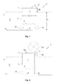
- a hydroenergy generating plant 5 is shown in Figure 1 .
- a water-tight construction or container 1 is arranged in a body of water 11, such as a sea or a lake or other body of water.
- Mainly vertical walls 6 define inside them a reservoir 7 with the form of a cylinder.
- the form of the reservoir is not limited to a cylinder, but its form may be arbitrarily chosen according to the needs.
- the reservoir form may be similar to a honeycomb, square, hexagonal, elliptical etc.
- the walls 6 may be made e.g. of steel or concrete.
- Top 8 of the walls 6 reaches a distance D2 over the sea level 2.
- the distance D2 can be e.g. 0.5-20 m, 1-10 m or 2-5 m.
- the container 1 is attached or built in such a way that it stays firmly in the sea bottom 4.
- Distance D1 from the sea level 2 to bottom of the sea 4 may be in range of several tens of meters.
- the distance D1 can be e.g. 1-100 m, 10-60 m or 20-50 m.
- the diameter D3 of the circular container can be e.g. 5-300 m, 30-200 m or 40-150 m
- the container 1 has one or more pumps units and/or generator units 12 and 14 installed in the walls, near the bottom of the sea 4. Pumps are used to pump water out of the container 1.
- the water level 3 in the container therefore goes down as water is pumped. This phase is called as storing energy.
- the generators 12 and/or 14 let the water to go in the container 1 leading to rise of water level 3 in the container 1.
- electricity is formed.
- the structure could be built directly to bottom 4 of the body of water 11 with the bottom 4 functioning as a bottom 9 of the container.
- the bottom 9 of the container can be for example of concrete or steel.
- the container may thus be open or closed at the top. If the container 1 is closed it may be made at least mainly air-tight. In one embodiment the horizontal cross-section of the container 1 is mainly round, i.e. a circle.
- the amount and type of pumps or pump units as well as the amount and type of generators or generator units 12, 14 can be varied as needed. In an advantageous embodiment they are situated in the lower part of the construction and the container 1.
- the hydroenergy generating plant 5 comprises one ore more reversible turbine/generator assemblies 12, 14, which can both pump water out from the container and produce electricity when water is led in the container through them.
- Assemblies 12, 14 include closing valves to control flow of the water in and out of the container.
- the embodiment of Figure 1 can be run in any place with access to an electricity grid.
- One possible installation of the plant 5 could be close to a nuclear power plant or other electricity plant to be used as storage of excess electricity.
- the hydroenergy generating plant 5 can be arranged to function without any need of input electricity.
- the storing of energy, i.e. the emptying of the container 1 can be done using e.g. wind, wave or solar energy.
- Figure 2 shows how conventional wind operated water pumps can be used to pump the container empty.
- a wind turbine 16 is arranged to pump water near the bottom 9 of the container with a pump 18. Water is pumped out via valve 20. When electricity is needed, water is led into the container via generator unit 12. Wind turbine 16 can alternatively be replaced by solar panels. When using solar panels the energy generated by panels could be used to run pumps to empty container. Also, for example motion created by waves in an ocean could be used to pump the container 1 empty.
- the hydroenergy generating plant 5 comprises a compressed air energy storage.
- the top of the container 1 is covered with a water and air tight roof 10.
- the emptying of the structure could be done by pumping air to the structure 1 with a unit 22 with an air pump and allowing the water to leave the structure near the bottom 9 of the container via removal means 24.
- removal means 24 also comprises inlet means and a generator unit, electricity can be created by leading water in through unit 24.
- the unit 22 comprises a generator unit electricity would be produced by having air flow out via a turbine in unit 22.
- the plant 5 could be built as a simple "diving bell" with open bottom or just one or more openings in the bottom part of the walls 6.
- Preferred output power might be one with most energy efficiency or for example one with combination of energy efficiency and loading of generator.
- Some generators produce most Mega watts per unit of fuel at full output power but others have optimum point at less than maximum output power.
- diesel generators are recommended to run for example at 75 % of maximum output power possible from the generator in order to increase the life time of the generator. Full 100 % run is typically recommended only for limited time like few hours per month or day.
- One embodiment of the invention is to enable a power plant to run in "preferred operation point". In situations where there is no need to large output power energy would be stored in a plant according to the invention.
- the invention would also enable power plants from time to time to output more power than the nominal maximum capacity of the plant is i.e. >100% of normal maximum output power.
- a primary or secondary cooling system pumps of a nearby power plant could be used to empty the reservoir according to the invention.
- a primary or secondary cooling system pumps of a nearby power plant could be used to empty the reservoir according to the invention.
- One such embodiment is illustrated in Figure 5 .
- Secondary cooling water to a power plant 600 e.g. a nuclear power plant, is pumped with pumps 601 via pipes 610 from the container 1 of the hydroenergy generating plant 5 according to the invention.
- This sort of a system may be retrofitted to an existing power station.
- energy should not be stored or generated i.e. one should not store more energy or generate energy.
- Table 1 shows maximum and minimum hourly rates between 6 th May -13 th May 2009 of Swiss power market. There are significant price fluctuations in the market enabling energy storage business even with moderate efficiency on pumping and recovering electricity from the stored energy.
- Table 1 Undertag Max min Diff Delivery Date 13.05.2009 50,78 10,64 40,14 12.05.2009 48,06 10,94 37,12 11.05.2009 48,04 0,10 47,94 10.05.2009 32,81 3,22 29,59 09.05.2009 38,10 13,91 24,19 08.05.2009 43,08 15,33 27,75 07.05.2009 52,07 14,61 37,46 06.05.2009 44,58 6,70 37,88
- a computer system connected preferably via Internet to follow either real time or close real time, on a periodic manner or random manner the price and supply and demand of the electricity to make decision according to an algorithm or similar decision means.
- the decisions can be made using input from the processes and control data of the another power plant.
- the control data can be derived from overall loading information of the electricity grid and for example by calculating cumulative electricity supply/usage at given time. Additionally in large grids covering multiple time zones, like the one in Russia, statistical information related to consumption and production of energy in different time zones can be used to predict when and where to store and/or generate energy.
- the decisions on if to hold, generate or pump could be made for example based on weather forecast.
- the inventive energy generating plant is controlled by a logic that gets preferably via Internet or other means weather information from sources such as meteorological institute to determine if the pumps should be used or not.
- an algorithm could for example use most of the wind energy for pumping water out (i.e. storing energy) it the forecast is that there will be lower wind speed or no wind in future compared to current wind. This way one would be able to "store” wind to ensure supply of "green” energy for those appreciating it.
- one or more server systems are connected to one or more energy generating plants according to the invention.
- Figure 6 presents one embodiment where two energy generating plants or energy storing systems 5 (ESS) are controlled by a control system 30.
- Number of energy storing systems 5 connected to one control system 30 can be one or more, e.g. 1-5, 1-10 or 1-50.
- Control system 30 and plants 5 are connected via a communication network 31.
- the system gets input data from various sources, e.g. weather information from weather service 32, market information 33 such as electricity price from market information providers, electricity producing price information, power plant information 34 from one or more power plants, grid loading information 35 from grid companies. Decisions on whether to store or produce energy with the plants 5 is made using the input data e.g. in an algorithm as described above.
- Data connections in the system with the communication network 31 are presented by lines in Figure 6 . Connections may be arranged with any suitable connectivity means such as Internet or wireless networks.
- FIGs 7 and 8 present a further embodiment of a hydroenergy generating plant 5 according to the invention much like the embodiment of Figure 1 .
- Plan 5 comprises a structure i.e. a container 1 arranged at the bottom 4 of a body of water 11.
- the bottom 4 of the body of water is used as the bottom 9 of the container.
- Bottom 9 could also be man-made, e.g. of steel.
- Container has mainly vertical steel walls 6 defining in them a cylindrical and an at least mainly water-tight reservoir 7 for water.
- Top 8 of the walls is above the water level 2 outside the container 1 so that large amounts of water cannot enter the reservoir unintentionally.
- a pump/generator unit 12 is arranged on the wall 6 of the container 1 near the bottom 4 of the body of water.
- the pump/generator unit 12 can be arranged to either pump water out of the container into the body of water 11 or to allow water flow into the reservoir whereby electricity is produced.
- D1 is the distance from sea bottom to sea level
- D2 is the distance from sea level to top of the walls
- D3 is the diameter of the circular container
- D4 is distance from the turbine axle of the pump/generator unit 12 to sea level.
- D4 defines the maximum output of the generator.
- the distance D4 may by e.g. more than 90 %, more than 95 % or more than 97 % one or both of distance D1 and height of the walls 6, i.e. D1+D2.
- the distance D5 is the height of water level 3 in the reservoir 7 from the bottom 9 of the reservoir 1.
- E 3.14 x D ⁇ 3 / 2 2 ⁇ x D ⁇ 4 x 1000 kg / m 3 ⁇ x 9.81 ⁇ m / sec 2 ⁇ x D ⁇ 4 / 2.
- Table 2 shows examples on the capability of the energy storing system according to the invention.
- reversible turbine modules are used both to pump the reservoir empty and to generate electricity.
- E 33.5 x 10 ⁇ 9 Joule.
- efficiency of 0.9 for pumping and energy generation this creates a possible energy capacity of 8.4 MWh per day.
- Larger size gives higher output, for example if D3 is 200 meters and D4 is 50 meters, the plant would have a capacity of almost 100 MWh per day.
- Table 2 12 h listing / 12 hs emplying PLATE SIZE 100/30 200/30 100/40 100/50 200/40 200/50 TANK Diameter [m] 100,0 100,0 100,0 200,0 200,0 200,0 Area [m2] 7,854 7,854 7,854 31,416 31,416 31,416 Depth [m] 30,0 40,0 50,0 30,0 40,0 50,0 Turbine depth [m] 29,5 39,5 49,5 29,5 39,5 49,5 Volume, total [m3] 235,619 314,159 392,699 942,478 1,258,837 1,570,796 Volume, effective [m3] 231,692 310,232 388,772 926,770 1,240,929 1,555,088 Water density [km/m3] 1,000 1,000 1,000 1,000 1,000 1,000 1,000 1,000 1,000 TURBINE Average flow [m3/g] 5,4 7,2 9,0 21,5 28,7 36,0 ENERGY mass of water [t] 231,692 310
- Figures 9 and 10 present further embodiments for a hydroenergy generating plant 5 according to the invention.
- the steel structure 1 is attached in the bottom 4 of the body of water 11.
- Structure 1 is constructed from eight segments 40, 40' attached to each other to form a substantial circle as shown in Figure 9 .
- Each wall segment 40, 40' forms a part of the whole circle form structure 1.
- a substantially water-tight reservoir 7 for water is formed inside wall segments 40, 40'.
- the number and size of segments 40, 40' may vary depending on the situation. All segments 40, 40' may be approximately of same size, as in Figure 9 .
- the wall segments 40, 40' are supported by bracing beams 41 to the bottom 9 of the reservoir 7. Support structures can be arranged towards the outside of the structure 1.
- the supporting bracing 41 may form triangle formations, as seen in Figure 9 .
- One of the segments 40' is drawn with a thicker line for illustrative purpose.
- the structure 1 comprises a service shaft 42, as shown in Figure 10 .
- Service shaft 42 reaches from the upper end 8 of the wall 6 along the wall 6 down to the pump/generator unit 12 near the bottom 4 of the body of water 11.
- Service shaft 42 can comprise stairs or an elevator or similar means.
- a structure 1 according to the invention may also comprise other service units, such as a pier for service boats or ships, control center of the power station and living quarters for personnel. These may be arranged on or near the upper end 8 of the walls.
- FIG. 11 One embodiment of a pump/generator unit 12 according to the invention is described in Figure 11 .
- a service shaft 42 reaches down to the unit 12, situated on the bottom 9 of the body of water 11.
- Water can be led through the wall 6 between the body of water 11 and the reservoir 7 via an outer opening 43, valve 13, turbine/pump wheel 17 and an inner opening 44.
- the axle of the turbine/pump wheel 17 is connected to a generator/motor 15 unit.
- the system is a so called reversible turbine/generator assembly, which can pump water out from the reservoir 7 or produce electricity depending on what is wanted.
- the generator/motor 15 unit is used as an electric motor which rotates the turbine/pump wheel 17 in such a way that water is pumped out from outer opening 43.
Landscapes
- Engineering & Computer Science (AREA)
- Chemical & Material Sciences (AREA)
- Combustion & Propulsion (AREA)
- Mechanical Engineering (AREA)
- General Engineering & Computer Science (AREA)
- Other Liquid Machine Or Engine Such As Wave Power Use (AREA)
Priority Applications (3)
| Application Number | Priority Date | Filing Date | Title |
|---|---|---|---|
| EP10151095A EP2345809A1 (fr) | 2010-01-19 | 2010-01-19 | Génération d'énergie hydro-électrique |
| US13/008,107 US8274168B2 (en) | 2010-01-19 | 2011-01-18 | Generating hydroenergy |
| GBGB1100822.4A GB201100822D0 (en) | 2010-01-19 | 2011-01-18 | Genrating hyrdoenergy |
Applications Claiming Priority (1)
| Application Number | Priority Date | Filing Date | Title |
|---|---|---|---|
| EP10151095A EP2345809A1 (fr) | 2010-01-19 | 2010-01-19 | Génération d'énergie hydro-électrique |
Publications (1)
| Publication Number | Publication Date |
|---|---|
| EP2345809A1 true EP2345809A1 (fr) | 2011-07-20 |
Family
ID=42235637
Family Applications (1)
| Application Number | Title | Priority Date | Filing Date |
|---|---|---|---|
| EP10151095A Withdrawn EP2345809A1 (fr) | 2010-01-19 | 2010-01-19 | Génération d'énergie hydro-électrique |
Country Status (3)
| Country | Link |
|---|---|
| US (1) | US8274168B2 (fr) |
| EP (1) | EP2345809A1 (fr) |
| GB (1) | GB201100822D0 (fr) |
Cited By (12)
| Publication number | Priority date | Publication date | Assignee | Title |
|---|---|---|---|---|
| WO2013000809A1 (fr) * | 2011-06-25 | 2013-01-03 | Armin Dadgar | Centrale hydraulique d'accumulation par pompage |
| WO2013044978A1 (fr) * | 2011-09-30 | 2013-04-04 | Seahorn Energy Holding ApS | Procédé de construction d'une installation de stockage d'énergie en mer et installation de stockage d'énergie en mer correspondante |
| DE102011118206A1 (de) * | 2011-11-11 | 2013-05-16 | Roentdek-Handels Gmbh | Pumpspeicherkraftwerk |
| DE102012100981A1 (de) * | 2012-02-07 | 2013-08-08 | Rainer Schramm | Unterwasserspeicher zum Speichern von vorzugsweise elektrischer Energie |
| FR3002597A1 (fr) * | 2013-02-25 | 2014-08-29 | Jean Louis Mansot | Centrale houlomotrice immergee |
| WO2014184312A1 (fr) * | 2013-05-15 | 2014-11-20 | Seahorn Energy Holding ApS | Centrale d'accumulation par pompage |
| NO20191109A1 (en) * | 2019-09-13 | 2021-03-15 | Hans Gude Gudesen | Energy island |
| US20230002993A1 (en) * | 2016-04-25 | 2023-01-05 | Alexander Arkady Migdal | Methods and water reservoir systems for generating, accumulating, storing, and releasing electrical energy |
| WO2023133290A1 (fr) * | 2022-01-07 | 2023-07-13 | Aswell Inc. | Barrages circulaires, systèmes de réservoir d'eau et procédés de fourniture d'énergie électrique constante |
| WO2023174549A1 (fr) * | 2022-03-17 | 2023-09-21 | Rh Power Gmbh | Centrale de stockage d'énergie par pompage |
| EP4286681A1 (fr) * | 2022-05-31 | 2023-12-06 | Sulzer Management AG | Système de stockage d'énergie |
| US11840815B2 (en) | 2016-04-25 | 2023-12-12 | Alexander Arkady Migdal | Circular dam and methods for generating, accumulating, storing, and releasing electrical energy |
Families Citing this family (6)
| Publication number | Priority date | Publication date | Assignee | Title |
|---|---|---|---|---|
| DE102011012594A1 (de) * | 2011-02-28 | 2012-08-30 | Universität Innsbruck | Hydraulischer Energiespeicher |
| DE102011115034A1 (de) * | 2011-10-07 | 2013-04-11 | Voith Patent Gmbh | Verfahren zur Primärregelung eines Wasserkraftwerks |
| ES2532652B1 (es) * | 2013-09-28 | 2016-01-22 | Manuel LÓPEZ LÓPEZ | Sistema de generación de energía undimotriz integrado en un cajón |
| KR101642948B1 (ko) * | 2015-04-24 | 2016-07-26 | 한국전력기술 주식회사 | 해상 부유식 발전장치 |
| US10408186B2 (en) | 2015-11-17 | 2019-09-10 | Adebukola Olatunde | Combined pump and turbine |
| US20180298874A1 (en) * | 2017-04-18 | 2018-10-18 | Logan Michael Turk | Pumped hydroelectric energy storage |
Citations (6)
| Publication number | Priority date | Publication date | Assignee | Title |
|---|---|---|---|---|
| US3214915A (en) * | 1963-01-29 | 1965-11-02 | English Electric Co Ltd | Reverse flow hydraulic pump-turbine systems |
| FR2438161A1 (fr) * | 1978-10-06 | 1980-04-30 | Grub Rainer | Dispositif pour la production de courant electrique par utilisation de la pression hydrostatique dans une masse d'eau |
| GB2032008A (en) * | 1978-10-25 | 1980-04-30 | Zeyher C H | Method of and means for generating hydro-electric power |
| US4211077A (en) * | 1978-06-29 | 1980-07-08 | Energy Kinematics, Inc. | Hybrid hydrostatic-pneumatic power generation system |
| US4443707A (en) | 1982-11-19 | 1984-04-17 | Frank Scieri | Hydro electric generating system |
| WO2007009192A1 (fr) * | 2005-07-22 | 2007-01-25 | Stephen John Hastings | Système de génération d'énergie |
Family Cites Families (6)
| Publication number | Priority date | Publication date | Assignee | Title |
|---|---|---|---|---|
| US5222833A (en) * | 1991-05-08 | 1993-06-29 | Northeastern University | Shutter for hydro-pneumatic current flow harnessing system |
| US7898102B2 (en) * | 1999-03-10 | 2011-03-01 | Wader, Llc | Hydrocratic generator |
| US20070284883A1 (en) * | 2006-06-07 | 2007-12-13 | Joseph Cafariello | Clean energy generation system |
| ITGE20060064A1 (it) * | 2006-06-16 | 2007-12-17 | Enrico Bozano | Impianto per la produzione di energia elettrica dal moto ondoso. |
| US20110109089A1 (en) * | 2009-08-19 | 2011-05-12 | Clarence Edward Frye | Free-flow hydro-powered turbine system |
| US8234861B2 (en) * | 2009-09-15 | 2012-08-07 | Clarence Edward Frye | Free flow hydro-powered hydraulic ram |
-
2010
- 2010-01-19 EP EP10151095A patent/EP2345809A1/fr not_active Withdrawn
-
2011
- 2011-01-18 US US13/008,107 patent/US8274168B2/en not_active Expired - Fee Related
- 2011-01-18 GB GBGB1100822.4A patent/GB201100822D0/en not_active Ceased
Patent Citations (6)
| Publication number | Priority date | Publication date | Assignee | Title |
|---|---|---|---|---|
| US3214915A (en) * | 1963-01-29 | 1965-11-02 | English Electric Co Ltd | Reverse flow hydraulic pump-turbine systems |
| US4211077A (en) * | 1978-06-29 | 1980-07-08 | Energy Kinematics, Inc. | Hybrid hydrostatic-pneumatic power generation system |
| FR2438161A1 (fr) * | 1978-10-06 | 1980-04-30 | Grub Rainer | Dispositif pour la production de courant electrique par utilisation de la pression hydrostatique dans une masse d'eau |
| GB2032008A (en) * | 1978-10-25 | 1980-04-30 | Zeyher C H | Method of and means for generating hydro-electric power |
| US4443707A (en) | 1982-11-19 | 1984-04-17 | Frank Scieri | Hydro electric generating system |
| WO2007009192A1 (fr) * | 2005-07-22 | 2007-01-25 | Stephen John Hastings | Système de génération d'énergie |
Cited By (18)
| Publication number | Priority date | Publication date | Assignee | Title |
|---|---|---|---|---|
| WO2013000809A1 (fr) * | 2011-06-25 | 2013-01-03 | Armin Dadgar | Centrale hydraulique d'accumulation par pompage |
| WO2013044978A1 (fr) * | 2011-09-30 | 2013-04-04 | Seahorn Energy Holding ApS | Procédé de construction d'une installation de stockage d'énergie en mer et installation de stockage d'énergie en mer correspondante |
| DE102011118206A1 (de) * | 2011-11-11 | 2013-05-16 | Roentdek-Handels Gmbh | Pumpspeicherkraftwerk |
| US9797366B2 (en) | 2011-11-11 | 2017-10-24 | Roentdek-Handels | Pumped-storage power plant |
| DE102012100981A1 (de) * | 2012-02-07 | 2013-08-08 | Rainer Schramm | Unterwasserspeicher zum Speichern von vorzugsweise elektrischer Energie |
| FR3002597A1 (fr) * | 2013-02-25 | 2014-08-29 | Jean Louis Mansot | Centrale houlomotrice immergee |
| WO2014184312A1 (fr) * | 2013-05-15 | 2014-11-20 | Seahorn Energy Holding ApS | Centrale d'accumulation par pompage |
| US20230002993A1 (en) * | 2016-04-25 | 2023-01-05 | Alexander Arkady Migdal | Methods and water reservoir systems for generating, accumulating, storing, and releasing electrical energy |
| US11840815B2 (en) | 2016-04-25 | 2023-12-12 | Alexander Arkady Migdal | Circular dam and methods for generating, accumulating, storing, and releasing electrical energy |
| US11639590B2 (en) * | 2016-04-25 | 2023-05-02 | Alexander Arkady Migdal | Methods and water reservoir systems for generating, accumulating, storing, and releasing electrical energy |
| WO2021049946A1 (fr) * | 2019-09-13 | 2021-03-18 | Hans Gude Gudesen | Procédé et système de construction d'îlot d'énergie |
| NO345885B1 (en) * | 2019-09-13 | 2021-09-27 | Hans Gude Gudesen | «Energy island construction method and system |
| NO20191109A1 (en) * | 2019-09-13 | 2021-03-15 | Hans Gude Gudesen | Energy island |
| US12110648B2 (en) | 2019-09-13 | 2024-10-08 | Hans Gude Gudesen | Energy island construction method and system |
| WO2023133290A1 (fr) * | 2022-01-07 | 2023-07-13 | Aswell Inc. | Barrages circulaires, systèmes de réservoir d'eau et procédés de fourniture d'énergie électrique constante |
| WO2023174549A1 (fr) * | 2022-03-17 | 2023-09-21 | Rh Power Gmbh | Centrale de stockage d'énergie par pompage |
| EP4286681A1 (fr) * | 2022-05-31 | 2023-12-06 | Sulzer Management AG | Système de stockage d'énergie |
| US12270369B2 (en) | 2022-05-31 | 2025-04-08 | Sulzer Management Ag | Energy storage system |
Also Published As
| Publication number | Publication date |
|---|---|
| US20120056430A1 (en) | 2012-03-08 |
| US8274168B2 (en) | 2012-09-25 |
| GB201100822D0 (en) | 2011-03-02 |
Similar Documents
| Publication | Publication Date | Title |
|---|---|---|
| EP2345809A1 (fr) | Génération d'énergie hydro-électrique | |
| US10344741B2 (en) | Hydro-pneumatic energy storage system | |
| US9617970B2 (en) | Pumped-storage power plant | |
| Kaldellis et al. | Optimal wind-hydro solution for Aegean Sea islands' electricity-demand fulfilment | |
| JP5964979B2 (ja) | 揚水発電所 | |
| Pimenta et al. | Simulating reservoir storage for a wind-hydro hydrid system | |
| EP4065832B1 (fr) | Production d'énergie et conservation de l'eau | |
| Klar et al. | Buoyant Energy—balancing wind power and other renewables in Europe’s oceans | |
| WO2023133290A1 (fr) | Barrages circulaires, systèmes de réservoir d'eau et procédés de fourniture d'énergie électrique constante | |
| US9657708B2 (en) | Pumped-storage system | |
| Tam et al. | Underground pumped hydro storage—An overview | |
| Halder et al. | Efficient hydroenergy conversion technologies, challenges, and policy implication | |
| Diawuo et al. | Characteristic features of pumped hydro energy storage systems | |
| US11840815B2 (en) | Circular dam and methods for generating, accumulating, storing, and releasing electrical energy | |
| US20230002993A1 (en) | Methods and water reservoir systems for generating, accumulating, storing, and releasing electrical energy | |
| Hote et al. | Global offshore wind scenario: A review | |
| JP6675633B2 (ja) | 発電装置 | |
| JP5787943B2 (ja) | 電力貯蔵システムおよび電力貯蔵方法 | |
| Kubiak-Wójcicka et al. | Exploitation of rivers in Poland for electricity Production–Current condition and perspectives for development | |
| EP4649235A1 (fr) | Stockage d'énergie potentielle submersible et puissance | |
| JP2014051970A5 (fr) | ||
| Crastan | Power Generation | |
| US20240318639A1 (en) | Energy Production from Deep Ocean Pressure | |
| Dragu et al. | Small-Scale Renewable Energy in the Next Century Market Hydro Plants–State of the Art and Applications. | |
| Abudabbous | Harnessing Hydraulic Potential: Integrating In-Pipe Hydropower into Libya's Great Man-Made River Project |
Legal Events
| Date | Code | Title | Description |
|---|---|---|---|
| PUAI | Public reference made under article 153(3) epc to a published international application that has entered the european phase |
Free format text: ORIGINAL CODE: 0009012 |
|
| AK | Designated contracting states |
Kind code of ref document: A1 Designated state(s): AT BE BG CH CY CZ DE DK EE ES FI FR GB GR HR HU IE IS IT LI LT LU LV MC MK MT NL NO PL PT RO SE SI SK SM TR |
|
| AX | Request for extension of the european patent |
Extension state: AL BA RS |
|
| STAA | Information on the status of an ep patent application or granted ep patent |
Free format text: STATUS: THE APPLICATION IS DEEMED TO BE WITHDRAWN |
|
| 18D | Application deemed to be withdrawn |
Effective date: 20120121 |