EP2345814A2 - Querstromlüfter und Klimaanlage damit - Google Patents
Querstromlüfter und Klimaanlage damit Download PDFInfo
- Publication number
- EP2345814A2 EP2345814A2 EP11150299A EP11150299A EP2345814A2 EP 2345814 A2 EP2345814 A2 EP 2345814A2 EP 11150299 A EP11150299 A EP 11150299A EP 11150299 A EP11150299 A EP 11150299A EP 2345814 A2 EP2345814 A2 EP 2345814A2
- Authority
- EP
- European Patent Office
- Prior art keywords
- cross
- flow fan
- blade
- uplift portion
- blade body
- Prior art date
- Legal status (The legal status is an assumption and is not a legal conclusion. Google has not performed a legal analysis and makes no representation as to the accuracy of the status listed.)
- Granted
Links
Images



Classifications
-
- F—MECHANICAL ENGINEERING; LIGHTING; HEATING; WEAPONS; BLASTING
- F04—POSITIVE - DISPLACEMENT MACHINES FOR LIQUIDS; PUMPS FOR LIQUIDS OR ELASTIC FLUIDS
- F04D—NON-POSITIVE-DISPLACEMENT PUMPS
- F04D29/00—Details, component parts, or accessories
- F04D29/26—Rotors specially for elastic fluids
- F04D29/28—Rotors specially for elastic fluids for centrifugal or helico-centrifugal pumps for radial-flow or helico-centrifugal pumps
- F04D29/281—Rotors specially for elastic fluids for centrifugal or helico-centrifugal pumps for radial-flow or helico-centrifugal pumps for fans or blowers
- F04D29/282—Rotors specially for elastic fluids for centrifugal or helico-centrifugal pumps for radial-flow or helico-centrifugal pumps for fans or blowers the leading edge of each vane being substantially parallel to the rotation axis
- F04D29/283—Rotors specially for elastic fluids for centrifugal or helico-centrifugal pumps for radial-flow or helico-centrifugal pumps for fans or blowers the leading edge of each vane being substantially parallel to the rotation axis rotors of the squirrel-cage type
-
- F—MECHANICAL ENGINEERING; LIGHTING; HEATING; WEAPONS; BLASTING
- F04—POSITIVE - DISPLACEMENT MACHINES FOR LIQUIDS; PUMPS FOR LIQUIDS OR ELASTIC FLUIDS
- F04D—NON-POSITIVE-DISPLACEMENT PUMPS
- F04D17/00—Radial-flow pumps, e.g. centrifugal pumps; Helico-centrifugal pumps
- F04D17/02—Radial-flow pumps, e.g. centrifugal pumps; Helico-centrifugal pumps having non-centrifugal stages, e.g. centripetal
- F04D17/04—Radial-flow pumps, e.g. centrifugal pumps; Helico-centrifugal pumps having non-centrifugal stages, e.g. centripetal of transverse-flow type
-
- F—MECHANICAL ENGINEERING; LIGHTING; HEATING; WEAPONS; BLASTING
- F04—POSITIVE - DISPLACEMENT MACHINES FOR LIQUIDS; PUMPS FOR LIQUIDS OR ELASTIC FLUIDS
- F04D—NON-POSITIVE-DISPLACEMENT PUMPS
- F04D29/00—Details, component parts, or accessories
- F04D29/26—Rotors specially for elastic fluids
- F04D29/28—Rotors specially for elastic fluids for centrifugal or helico-centrifugal pumps for radial-flow or helico-centrifugal pumps
- F04D29/30—Vanes
-
- F—MECHANICAL ENGINEERING; LIGHTING; HEATING; WEAPONS; BLASTING
- F04—POSITIVE - DISPLACEMENT MACHINES FOR LIQUIDS; PUMPS FOR LIQUIDS OR ELASTIC FLUIDS
- F04D—NON-POSITIVE-DISPLACEMENT PUMPS
- F04D29/00—Details, component parts, or accessories
- F04D29/66—Combating cavitation, whirls, noise, vibration or the like; Balancing
- F04D29/661—Combating cavitation, whirls, noise, vibration or the like; Balancing especially adapted for elastic fluid pumps
- F04D29/663—Sound attenuation
-
- F—MECHANICAL ENGINEERING; LIGHTING; HEATING; WEAPONS; BLASTING
- F04—POSITIVE - DISPLACEMENT MACHINES FOR LIQUIDS; PUMPS FOR LIQUIDS OR ELASTIC FLUIDS
- F04D—NON-POSITIVE-DISPLACEMENT PUMPS
- F04D29/00—Details, component parts, or accessories
- F04D29/66—Combating cavitation, whirls, noise, vibration or the like; Balancing
- F04D29/68—Combating cavitation, whirls, noise, vibration or the like; Balancing by influencing boundary layers
- F04D29/681—Combating cavitation, whirls, noise, vibration or the like; Balancing by influencing boundary layers especially adapted for elastic fluid pumps
-
- F—MECHANICAL ENGINEERING; LIGHTING; HEATING; WEAPONS; BLASTING
- F24—HEATING; RANGES; VENTILATING
- F24F—AIR-CONDITIONING; AIR-HUMIDIFICATION; VENTILATION; USE OF AIR CURRENTS FOR SCREENING
- F24F1/00—Room units for air-conditioning, e.g. separate or self-contained units or units receiving primary air from a central station
- F24F1/0007—Indoor units, e.g. fan coil units
- F24F1/0018—Indoor units, e.g. fan coil units characterised by fans
- F24F1/0025—Cross-flow or tangential fans
Definitions
- the present disclosure relates to a cross-flow fan and an air conditioner including the same.
- a cross-flow fan is referred to as a tangential fan.
- the cross-flow fan includes one or more fan blocks, which include a plurality of blades curved in a rotation direction.
- a suction flow does not occur in an axial direction, but occurs within a plane perpendicular to a shaft of the fan blocks.
- the cross-flow fan may be widely applicable to a blower such as an air conditioner as well as may be applicable to a display device to cool a display module.
- the cross-flow fan has a limitation in that a lot of noise occurs due to air current passing through the blades constituting the fan block.
- Embodiments provide a low-noise cross-flow fan having an improved structure of a blade constituting an impeller and an air conditioner including the low-noise cross-flow fan.
- a cross-flow fan including: a plurality of blades radially disposed relative to a rotation axis, the plurality of blades being spaced from each other along a circumference direction; and a supporting plate supporting the blades is characterized in that an uplift portion protrudes from the respective blades, and the uplift portion extends from an inner end of the blade to an outer end.
- Fig. 1 is a side sectional view of an air conditioner including a cross-flow fan according to an embodiment.
- Fig. 2 is a perspective view of a cross-flow fan according to an embodiment.
- Fig. 3 is a perspective view of a blade constituting the cross-flow fan.
- Fig. 4 is a side view of a cross-flow fan according to an embodiment.
- Fig. 5 is an enlarged view illustrating a portion A of Fig. 3 .
- Fig. 6 is a sectional view taken along line I-I of Fig. 3 that illustrates a blade according to a first embodiment.
- Fig. 7 is a schematic sectional view of a flow occurring on the blade according to the first embodiment.
- Fig. 8 is a simulation comparing an airflow occurring in a cross-fan according to a related art to an airflow occurring in a cross-fan according to an embodiment.
- Fig. 9 is a sectional view taken along line I-I of Fig. 3 that illustrates a blade according to a second embodiment.
- Fig. 10 is a sectional view taken along line I-I of Fig. 3 that illustrates a blade according to a third embodiment.
- Fig. 1 is a side sectional view of an air conditioner including a cross-flow fan according to an embodiment.
- an air conditioner 10 includes a body 11 defining an outer appearance thereof, a heat exchanger 12 disposed inside the body 11, and a cross-flow fan 20 disposed under the heat exchanger 12 to discharge air passing through the heat exchanger 12 to the outside.
- a suction grill 111 is disposed in a side of the body 11, i.e., a top surface of the body 11 to suck indoor air into the body 11.
- a separate suction hole may be defined in a front surface of the body 11 and selectively opened or closed by a suction panel 112.
- a filter 13 may be disposed at a rear side of the suction hole closed by the suction grill 111 and the suction panel 112 to filter foreign substances contained in sucked air.
- Air suction and discharge of the cross-flow fan 20 are guided by a discharge guide 14.
- a discharge end of the discharge guide 14 communicates with the discharge hole 113 defined in a lower side of the body 11.
- a discharge louver 115 and a discharge vane 114 may be disposed in the discharge hole 113.
- the discharge louver 115 may guide a horizontal airflow of discharged air
- the discharge vane 114 may guide a vertical airflow of the discharged air.
- the discharge vane 114 may selectively close the discharge hole 113.
- the discharge guide 14 includes a stabilizer 142 disposed spaced from an edge of one side of the cross-flow fan 20 and a rear guide 141 disposed spaced from an edge of the other side of the cross-flow fan 20.
- Fig. 2 is a perspective view of a cross-flow fan according to an embodiment
- Fig. 3 is a perspective view of a blade constituting the cross-flow fan.
- the cross-flow fan 20 includes a plurality of fan blocks 210 coupled to each other.
- each of the fan blocks 210 includes a plurality of blades 230 radially arranged at a uniform pitch or a random pitch with respect to a rotation shaft and a supporting plate 220 having a circular plate and supporting an end of each of the blades 230.
- the rotation shaft of the cross-flow fan 20 passes through a center of the supporting plate 220.
- Each of the plurality of blades 230 constituting the fan blocks 210 includes a blade body 231 and uplift portions 232 protruding with a distance therebetween in a length direction of the blade body 231.
- a length of each of the blades 230 is defined as a span S
- a width of each of the blades 230 perpendicular to the length direction is defined as a chord L.
- a side end adjacent to the rotation shaft of the cross-flow fan 20 is defined as an inner edge 233
- a side end opposite to the side end adjacent to the rotation shaft is defined as an outer edge 234.
- a diameter of a circle connecting the inner edges 233 of the blades 230 to each other is defined as a fan inner diameter D1
- a diameter of a circular connecting outer edges 234 of the blades 230 is defined as a fan outer diameter D2 (refer to Fig. 4 ).
- the blade 230 has a curved shape having a predetermined curvature in a width direction.
- a negative-pressure surface defining an outer surface of the cross-flow fan 20 has a curvature different from that of a positive-pressure surface receiving an air pressure on a surface opposite to the negative-pressure surface.
- a distance between the negative-pressure surface and the positive-pressure surface is defined as a thickness of the blade 230
- a volume between the negative-pressure surface and the positive-pressure surface is defined as a thickness t of the blade body 231.
- the thickness of the blade body 231 is the thickest at a point at which the width of the blade 230 is bisected.
- a line bisecting the thickness of the blade 230 is defined as a camber line.
- Each of the uplift portions 232 is disposed from the inner edge 233 from the blade body 231 to the outer edge 234. Also, the uplift portion 232 protrudes in a shape having a width gradually decreasing upward or in a circularly rounded shape.
- Fig. 4 is a side view of a cross-flow fan according to an embodiment.
- the cross-flow fan 20 has a shape in which the plurality of blades 230 is radially arranged from a point spaced a predetermined distance from a rotation center.
- a mean camber line is defined by an inner blade tip angle ⁇ 1 and an outer blade tip angle ⁇ 2 of each of the blades 230.
- the inner blade tip angle ⁇ 1 represents an angle between a tangent line h1 of a circle passing through the inner edge 233 of the blade 230 and a tangent line h2 passing through the mean chamber line at the inner edge 233.
- the outer blade tip angel ⁇ 2 represents an angle between a tangent line h3 of a circle passing through the outer edge 234 of the blade 230 and a tangent line h4 passing through the mean camber line at the outer edge 234.
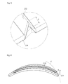
- Fig. 5 is an enlarged view illustrating a portion A of Fig. 3 .
- the plurality of uplift portions 232 is disposed on the blade 230 according to an embodiment with a predetermined distance.
- the uplift portions 232 protrude from the negative-pressure surface of the blade 230.
- each of the uplift portions 232 protrudes in a triangular shape having a width gradually decreasing upward.
- an end of the outer edge 234 side of at least the blade 230 of both ends of each of the uplift portions 232 is curved with the same curvature as that of an outer peripheral arc k of the cross-flow fan 20.
- the end of the outer edge 234 side of the blade 230 is referred to as an outer end
- an end of the inner edge 233 side of the blade 230 is referred to as an inner end.
- a cusp of the outer end of each of the uplift portions 232 is spaced a predetermined length p from the tangent line passing through the outer edge 234 of the blade 230. This occurs because the outer end of the uplift portion 232 is curved with the same curvature as that of the outer peripheral arc k of the cross-flow fan 20, and also may be clearly confirmed through Fig. 6 .
- the uplift portion 232 is disposed on the negative-pressure surface of the blade 230 and the outer end of at least the uplift portion 232 is curved with the same curvature as that of the outer peripheral arc k of the cross-flow fan 20, air passing through the cross-flow fan 20 may be reduced in turbulence intensity to significantly reduce noises.
- Fig. 6 is a sectional view taken along line I-I of Fig. 3 that illustrates a blade according to a first embodiment.
- an uplift portion 232 of a blade 230 has a section similar to that of a blade body 231.
- the blade 230 has two sections different from each other. That is to say, the section of the blade body 231 overlaps the section of the uplift portion 232.
- the uplift potion 232 has an inner edge and an outer edge.
- the uplift portion 232 has a chamber line bisecting a thickness thereof and a chord defining a width thereof.
- the blade 230 may have a sectional shape varied according to sizes of inner and outer blade tip angles ⁇ 1 and ⁇ 2 and inner and outer blade tip angles of the uplift portion.
- the blade body 231 has a chord length greater than that of the uplift portion 232. Also, the blade body 231 has the same inner and outer blade tip angles as those of the uplift portion 232.
- Fig. 7 is a schematic sectional view of a flow occurring on the blade according to the first embodiment.
- air forcedly flowing by the cross-flow fan 20 flows along a positive-pressure surface of the blade 23.
- the air flowing along the positive-pressure surface of the blade 23 is divided by the outer end of the blade 23.
- air discharged along a recessed surface of an inner side of the uplift portion 232 and a portion of air discharged along the positive-pressure surface of the blade body 231 are bent toward the negative-pressure surface of the blade 23. This is done because a pressure difference between the negative-pressure surface of the blade 23 and the positive-pressure surface of the blade body 231 occurs, and thus it has an influence on a flow of air flowing from a high pressure to a low pressure.
- the air bent at the outer end of the blade body 231 is interrupted by the air discharged at the end of the uplift portion 232. Therefore, the air flowing along the positive-pressure surface of the blade body 231 may be smoothly discharged, and thus, an amount of air may be increased as well as the noises may be reduced.
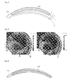
- Fig. 8 is a simulation comparing an airflow occurring in a cross-fan according to a related art to an airflow occurring in a cross-fan according to an embodiment.
- a left side of Fig. 8 illustrates an airflow occurring in a cross-flow fan region according to a related art
- a right side of Fig. 8 illustrates an airflow occurring in a cross-flow fan region according to an embodiment.
- Fig. 9 is a sectional view taken along line I-I of Fig. 3 that illustrates a blade according to a second embodiment.
- a blade body 231 has a chord length greater than that of an uplift portion 232. Also, the blade body 231 has the same inner blade tip angle as that of the uplift portion 232. However, the blade body 232 has an outer blade tip angle greater than that of the uplift portion.
- Fig. 10 is a sectional view taken along line I-I of Fig. 3 that illustrates a blade according to a third embodiment.
- a blade body 231 has the same chord length as that of an uplift portion 232. Also, the blade body 231 has the same outer blade tip angle as that of the uplift portion 232. However, the blade body 231 has an inner blade tip angle less than that of the uplift portion 232.
- the noises due to the air passing through the blade may be reduced. That is, the turbulence intensity at the discharge part of the fan block may be reduced to reduce the noises.
Landscapes
- Engineering & Computer Science (AREA)
- Mechanical Engineering (AREA)
- General Engineering & Computer Science (AREA)
- Chemical & Material Sciences (AREA)
- Combustion & Propulsion (AREA)
- Structures Of Non-Positive Displacement Pumps (AREA)
- Air-Conditioning Room Units, And Self-Contained Units In General (AREA)
Applications Claiming Priority (1)
| Application Number | Priority Date | Filing Date | Title |
|---|---|---|---|
| KR1020100003044A KR101649379B1 (ko) | 2010-01-13 | 2010-01-13 | 횡류팬 및 이를 구비한 공기 조화기 |
Publications (3)
| Publication Number | Publication Date |
|---|---|
| EP2345814A2 true EP2345814A2 (de) | 2011-07-20 |
| EP2345814A3 EP2345814A3 (de) | 2012-10-10 |
| EP2345814B1 EP2345814B1 (de) | 2015-04-08 |
Family
ID=43759340
Family Applications (1)
| Application Number | Title | Priority Date | Filing Date |
|---|---|---|---|
| EP11150299.3A Not-in-force EP2345814B1 (de) | 2010-01-13 | 2011-01-06 | Querstromlüfter und Klimaanlage damit |
Country Status (3)
| Country | Link |
|---|---|
| EP (1) | EP2345814B1 (de) |
| KR (1) | KR101649379B1 (de) |
| CN (1) | CN102128172B (de) |
Cited By (4)
| Publication number | Priority date | Publication date | Assignee | Title |
|---|---|---|---|---|
| WO2015063851A1 (ja) * | 2013-10-29 | 2015-05-07 | 三菱電機株式会社 | 貫流ファン及び空気調和機 |
| WO2015063850A1 (ja) * | 2013-10-29 | 2015-05-07 | 三菱電機株式会社 | 貫流ファン及び空気調和機 |
| CN118959354A (zh) * | 2024-09-24 | 2024-11-15 | 宁波市天超通风设备有限公司 | 一种台阶式叶轮结构及其加工方法 |
| WO2025115771A1 (ja) * | 2023-11-28 | 2025-06-05 | ダイキン工業株式会社 | クロスフローファン及び空気調和機 |
Families Citing this family (2)
| Publication number | Priority date | Publication date | Assignee | Title |
|---|---|---|---|---|
| WO2014080494A1 (ja) | 2012-11-22 | 2014-05-30 | 三菱電機株式会社 | 空気調和機 |
| CN106321473B (zh) * | 2016-09-05 | 2019-02-05 | 青岛海尔空调器有限总公司 | 用于空调器的贯流风机 |
Family Cites Families (11)
| Publication number | Priority date | Publication date | Assignee | Title |
|---|---|---|---|---|
| JPS61112797A (ja) * | 1984-11-05 | 1986-05-30 | Matsushita Electric Ind Co Ltd | 樹脂製送風フアン |
| JPH03210094A (ja) * | 1990-01-11 | 1991-09-13 | Matsushita Electric Ind Co Ltd | クロスフローファン |
| JP2822934B2 (ja) * | 1995-06-30 | 1998-11-11 | ダイキン工業株式会社 | クロスフローファン |
| JPH1077989A (ja) * | 1996-09-02 | 1998-03-24 | Toshiba Corp | 横流ファン |
| KR19990056525A (ko) * | 1997-12-29 | 1999-07-15 | 오상수 | 송풍기 유니트 |
| JP2002048085A (ja) * | 2000-07-28 | 2002-02-15 | Mitsubishi Electric Corp | 多連型多翼送風機用羽根車、多連型多翼送風機および空気調和機 |
| JP2005120877A (ja) * | 2003-10-15 | 2005-05-12 | Haruo Yoshida | 横断流送風機用羽根車および横断流送風機 |
| KR20050099352A (ko) * | 2004-04-09 | 2005-10-13 | 엘지전자 주식회사 | 전면 흡토출 방식의 공기조화기용 실외기 |
| JP2006002691A (ja) * | 2004-06-18 | 2006-01-05 | Calsonic Kansei Corp | 送風機 |
| JP4840343B2 (ja) * | 2007-11-30 | 2011-12-21 | 三菱電機株式会社 | 貫流ファン及び空気調和機 |
| JP4433093B2 (ja) * | 2008-05-09 | 2010-03-17 | ダイキン工業株式会社 | クロスフローファン及びこれを備えた空気調和機 |
-
2010
- 2010-01-13 KR KR1020100003044A patent/KR101649379B1/ko active Active
-
2011
- 2011-01-06 EP EP11150299.3A patent/EP2345814B1/de not_active Not-in-force
- 2011-01-13 CN CN2011100210576A patent/CN102128172B/zh not_active Expired - Fee Related
Non-Patent Citations (1)
| Title |
|---|
| None |
Cited By (10)
| Publication number | Priority date | Publication date | Assignee | Title |
|---|---|---|---|---|
| WO2015063851A1 (ja) * | 2013-10-29 | 2015-05-07 | 三菱電機株式会社 | 貫流ファン及び空気調和機 |
| WO2015063850A1 (ja) * | 2013-10-29 | 2015-05-07 | 三菱電機株式会社 | 貫流ファン及び空気調和機 |
| WO2015064617A1 (ja) * | 2013-10-29 | 2015-05-07 | 三菱電機株式会社 | 貫流ファン及び空気調和機 |
| JPWO2015064617A1 (ja) * | 2013-10-29 | 2017-03-09 | 三菱電機株式会社 | 貫流ファン及び空気調和機 |
| JPWO2015063851A1 (ja) * | 2013-10-29 | 2017-03-09 | 三菱電機株式会社 | 貫流ファン及び空気調和機 |
| EP3064776A4 (de) * | 2013-10-29 | 2017-07-19 | Mitsubishi Electric Corporation | Querstromlüfter und klimaanlage |
| EP3064777A4 (de) * | 2013-10-29 | 2017-07-19 | Mitsubishi Electric Corporation | Querstromlüfter und klimaanlage |
| WO2025115771A1 (ja) * | 2023-11-28 | 2025-06-05 | ダイキン工業株式会社 | クロスフローファン及び空気調和機 |
| JP2025086648A (ja) * | 2023-11-28 | 2025-06-09 | ダイキン工業株式会社 | クロスフローファン及び空気調和機 |
| CN118959354A (zh) * | 2024-09-24 | 2024-11-15 | 宁波市天超通风设备有限公司 | 一种台阶式叶轮结构及其加工方法 |
Also Published As
| Publication number | Publication date |
|---|---|
| CN102128172A (zh) | 2011-07-20 |
| CN102128172B (zh) | 2013-06-26 |
| EP2345814B1 (de) | 2015-04-08 |
| EP2345814A3 (de) | 2012-10-10 |
| KR20110083043A (ko) | 2011-07-20 |
| KR101649379B1 (ko) | 2016-08-30 |
Similar Documents
| Publication | Publication Date | Title |
|---|---|---|
| KR100985958B1 (ko) | 다익 팬 | |
| CN103597288B (zh) | 空气调节机 | |
| EP2902639B1 (de) | Propellerlüfter und klimaanlage damit | |
| EP2345814B1 (de) | Querstromlüfter und Klimaanlage damit | |
| CN101990604A (zh) | 离心鼓风机 | |
| KR102143389B1 (ko) | 원심팬 및 이를 포함하는 공기조화기 | |
| CN101821513A (zh) | 离心式风扇 | |
| CN1985092A (zh) | 离心式鼓风机及具有离心式鼓风机的空调装置 | |
| KR20130041639A (ko) | 시로코팬 및 그를 갖는 공기조화기 | |
| CN103958900B (zh) | 多叶片风扇及具备该多叶片风扇的空气调节器 | |
| JP2009203897A (ja) | 多翼送風機 | |
| JP6078945B2 (ja) | 遠心送風機 | |
| TW201934888A (zh) | 軸流風扇 | |
| JP2010174852A (ja) | クロスフローファンおよびそれを備えた空気調和機 | |
| JP6330738B2 (ja) | 遠心送風機及びこれを用いた空気調和機 | |
| CN112065770B (zh) | 叶片、离心风机及电器设备 | |
| EP2902716A1 (de) | Klimaanlage | |
| CN101395381B (zh) | 涡轮风扇和空调机 | |
| JP2001280288A (ja) | 多翼送風機の羽根車構造 | |
| KR100709819B1 (ko) | 횡류팬과 횡류팬을 구비한 공기조화기의 실내기 | |
| EP2280176B1 (de) | Querstromlüfter und klimaanlage damit | |
| CN110506164A (zh) | 螺旋桨式风扇及空调装置用室外机 | |
| CN106287959B (zh) | 静叶风轮、空调柜机及空调器 | |
| KR101826348B1 (ko) | 횡류팬 및 이를 구비한 공기 조화기 | |
| CN107061357A (zh) | 叶片、离心风机叶轮、离心风机和吸油烟机 |
Legal Events
| Date | Code | Title | Description |
|---|---|---|---|
| PUAI | Public reference made under article 153(3) epc to a published international application that has entered the european phase |
Free format text: ORIGINAL CODE: 0009012 |
|
| 17P | Request for examination filed |
Effective date: 20110106 |
|
| AK | Designated contracting states |
Kind code of ref document: A2 Designated state(s): AL AT BE BG CH CY CZ DE DK EE ES FI FR GB GR HR HU IE IS IT LI LT LU LV MC MK MT NL NO PL PT RO RS SE SI SK SM TR |
|
| AX | Request for extension of the european patent |
Extension state: BA ME |
|
| PUAL | Search report despatched |
Free format text: ORIGINAL CODE: 0009013 |
|
| AK | Designated contracting states |
Kind code of ref document: A3 Designated state(s): AL AT BE BG CH CY CZ DE DK EE ES FI FR GB GR HR HU IE IS IT LI LT LU LV MC MK MT NL NO PL PT RO RS SE SI SK SM TR |
|
| AX | Request for extension of the european patent |
Extension state: BA ME |
|
| RIC1 | Information provided on ipc code assigned before grant |
Ipc: F04D 29/28 20060101ALI20120905BHEP Ipc: F04D 17/04 20060101AFI20120905BHEP |
|
| 17Q | First examination report despatched |
Effective date: 20130719 |
|
| GRAP | Despatch of communication of intention to grant a patent |
Free format text: ORIGINAL CODE: EPIDOSNIGR1 |
|
| INTG | Intention to grant announced |
Effective date: 20141103 |
|
| GRAS | Grant fee paid |
Free format text: ORIGINAL CODE: EPIDOSNIGR3 |
|
| GRAA | (expected) grant |
Free format text: ORIGINAL CODE: 0009210 |
|
| AK | Designated contracting states |
Kind code of ref document: B1 Designated state(s): AL AT BE BG CH CY CZ DE DK EE ES FI FR GB GR HR HU IE IS IT LI LT LU LV MC MK MT NL NO PL PT RO RS SE SI SK SM TR |
|
| REG | Reference to a national code |
Ref country code: GB Ref legal event code: FG4D |
|
| REG | Reference to a national code |
Ref country code: CH Ref legal event code: EP |
|
| REG | Reference to a national code |
Ref country code: IE Ref legal event code: FG4D |
|
| REG | Reference to a national code |
Ref country code: AT Ref legal event code: REF Ref document number: 720810 Country of ref document: AT Kind code of ref document: T Effective date: 20150515 |
|
| REG | Reference to a national code |
Ref country code: DE Ref legal event code: R096 Ref document number: 602011015360 Country of ref document: DE Effective date: 20150521 |
|
| REG | Reference to a national code |
Ref country code: AT Ref legal event code: MK05 Ref document number: 720810 Country of ref document: AT Kind code of ref document: T Effective date: 20150408 |
|
| REG | Reference to a national code |
Ref country code: NL Ref legal event code: VDEP Effective date: 20150408 |
|
| REG | Reference to a national code |
Ref country code: LT Ref legal event code: MG4D |
|
| PG25 | Lapsed in a contracting state [announced via postgrant information from national office to epo] |
Ref country code: NL Free format text: LAPSE BECAUSE OF FAILURE TO SUBMIT A TRANSLATION OF THE DESCRIPTION OR TO PAY THE FEE WITHIN THE PRESCRIBED TIME-LIMIT Effective date: 20150408 |
|
| PG25 | Lapsed in a contracting state [announced via postgrant information from national office to epo] |
Ref country code: HR Free format text: LAPSE BECAUSE OF FAILURE TO SUBMIT A TRANSLATION OF THE DESCRIPTION OR TO PAY THE FEE WITHIN THE PRESCRIBED TIME-LIMIT Effective date: 20150408 Ref country code: NO Free format text: LAPSE BECAUSE OF FAILURE TO SUBMIT A TRANSLATION OF THE DESCRIPTION OR TO PAY THE FEE WITHIN THE PRESCRIBED TIME-LIMIT Effective date: 20150708 Ref country code: PT Free format text: LAPSE BECAUSE OF FAILURE TO SUBMIT A TRANSLATION OF THE DESCRIPTION OR TO PAY THE FEE WITHIN THE PRESCRIBED TIME-LIMIT Effective date: 20150810 Ref country code: LT Free format text: LAPSE BECAUSE OF FAILURE TO SUBMIT A TRANSLATION OF THE DESCRIPTION OR TO PAY THE FEE WITHIN THE PRESCRIBED TIME-LIMIT Effective date: 20150408 Ref country code: FI Free format text: LAPSE BECAUSE OF FAILURE TO SUBMIT A TRANSLATION OF THE DESCRIPTION OR TO PAY THE FEE WITHIN THE PRESCRIBED TIME-LIMIT Effective date: 20150408 Ref country code: ES Free format text: LAPSE BECAUSE OF FAILURE TO SUBMIT A TRANSLATION OF THE DESCRIPTION OR TO PAY THE FEE WITHIN THE PRESCRIBED TIME-LIMIT Effective date: 20150408 |
|
| PG25 | Lapsed in a contracting state [announced via postgrant information from national office to epo] |
Ref country code: AT Free format text: LAPSE BECAUSE OF FAILURE TO SUBMIT A TRANSLATION OF THE DESCRIPTION OR TO PAY THE FEE WITHIN THE PRESCRIBED TIME-LIMIT Effective date: 20150408 Ref country code: LV Free format text: LAPSE BECAUSE OF FAILURE TO SUBMIT A TRANSLATION OF THE DESCRIPTION OR TO PAY THE FEE WITHIN THE PRESCRIBED TIME-LIMIT Effective date: 20150408 Ref country code: GR Free format text: LAPSE BECAUSE OF FAILURE TO SUBMIT A TRANSLATION OF THE DESCRIPTION OR TO PAY THE FEE WITHIN THE PRESCRIBED TIME-LIMIT Effective date: 20150709 Ref country code: IS Free format text: LAPSE BECAUSE OF FAILURE TO SUBMIT A TRANSLATION OF THE DESCRIPTION OR TO PAY THE FEE WITHIN THE PRESCRIBED TIME-LIMIT Effective date: 20150808 Ref country code: RS Free format text: LAPSE BECAUSE OF FAILURE TO SUBMIT A TRANSLATION OF THE DESCRIPTION OR TO PAY THE FEE WITHIN THE PRESCRIBED TIME-LIMIT Effective date: 20150408 |
|
| REG | Reference to a national code |
Ref country code: FR Ref legal event code: PLFP Year of fee payment: 6 |
|
| REG | Reference to a national code |
Ref country code: DE Ref legal event code: R097 Ref document number: 602011015360 Country of ref document: DE |
|
| PG25 | Lapsed in a contracting state [announced via postgrant information from national office to epo] |
Ref country code: DK Free format text: LAPSE BECAUSE OF FAILURE TO SUBMIT A TRANSLATION OF THE DESCRIPTION OR TO PAY THE FEE WITHIN THE PRESCRIBED TIME-LIMIT Effective date: 20150408 Ref country code: EE Free format text: LAPSE BECAUSE OF FAILURE TO SUBMIT A TRANSLATION OF THE DESCRIPTION OR TO PAY THE FEE WITHIN THE PRESCRIBED TIME-LIMIT Effective date: 20150408 |
|
| PLBE | No opposition filed within time limit |
Free format text: ORIGINAL CODE: 0009261 |
|
| STAA | Information on the status of an ep patent application or granted ep patent |
Free format text: STATUS: NO OPPOSITION FILED WITHIN TIME LIMIT |
|
| PG25 | Lapsed in a contracting state [announced via postgrant information from national office to epo] |
Ref country code: RO Free format text: LAPSE BECAUSE OF NON-PAYMENT OF DUE FEES Effective date: 20150408 Ref country code: PL Free format text: LAPSE BECAUSE OF FAILURE TO SUBMIT A TRANSLATION OF THE DESCRIPTION OR TO PAY THE FEE WITHIN THE PRESCRIBED TIME-LIMIT Effective date: 20150408 Ref country code: SK Free format text: LAPSE BECAUSE OF FAILURE TO SUBMIT A TRANSLATION OF THE DESCRIPTION OR TO PAY THE FEE WITHIN THE PRESCRIBED TIME-LIMIT Effective date: 20150408 Ref country code: CZ Free format text: LAPSE BECAUSE OF FAILURE TO SUBMIT A TRANSLATION OF THE DESCRIPTION OR TO PAY THE FEE WITHIN THE PRESCRIBED TIME-LIMIT Effective date: 20150408 |
|
| 26N | No opposition filed |
Effective date: 20160111 |
|
| PG25 | Lapsed in a contracting state [announced via postgrant information from national office to epo] |
Ref country code: IT Free format text: LAPSE BECAUSE OF FAILURE TO SUBMIT A TRANSLATION OF THE DESCRIPTION OR TO PAY THE FEE WITHIN THE PRESCRIBED TIME-LIMIT Effective date: 20150408 |
|
| PG25 | Lapsed in a contracting state [announced via postgrant information from national office to epo] |
Ref country code: SI Free format text: LAPSE BECAUSE OF FAILURE TO SUBMIT A TRANSLATION OF THE DESCRIPTION OR TO PAY THE FEE WITHIN THE PRESCRIBED TIME-LIMIT Effective date: 20150408 Ref country code: BE Free format text: LAPSE BECAUSE OF NON-PAYMENT OF DUE FEES Effective date: 20160131 |
|
| PG25 | Lapsed in a contracting state [announced via postgrant information from national office to epo] |
Ref country code: LU Free format text: LAPSE BECAUSE OF FAILURE TO SUBMIT A TRANSLATION OF THE DESCRIPTION OR TO PAY THE FEE WITHIN THE PRESCRIBED TIME-LIMIT Effective date: 20160106 Ref country code: BE Free format text: LAPSE BECAUSE OF FAILURE TO SUBMIT A TRANSLATION OF THE DESCRIPTION OR TO PAY THE FEE WITHIN THE PRESCRIBED TIME-LIMIT Effective date: 20150408 |
|
| REG | Reference to a national code |
Ref country code: CH Ref legal event code: PL |
|
| PG25 | Lapsed in a contracting state [announced via postgrant information from national office to epo] |
Ref country code: MC Free format text: LAPSE BECAUSE OF FAILURE TO SUBMIT A TRANSLATION OF THE DESCRIPTION OR TO PAY THE FEE WITHIN THE PRESCRIBED TIME-LIMIT Effective date: 20150408 |
|
| PG25 | Lapsed in a contracting state [announced via postgrant information from national office to epo] |
Ref country code: CH Free format text: LAPSE BECAUSE OF NON-PAYMENT OF DUE FEES Effective date: 20160131 Ref country code: LI Free format text: LAPSE BECAUSE OF NON-PAYMENT OF DUE FEES Effective date: 20160131 |
|
| REG | Reference to a national code |
Ref country code: IE Ref legal event code: MM4A |
|
| REG | Reference to a national code |
Ref country code: FR Ref legal event code: PLFP Year of fee payment: 7 |
|
| PG25 | Lapsed in a contracting state [announced via postgrant information from national office to epo] |
Ref country code: IE Free format text: LAPSE BECAUSE OF NON-PAYMENT OF DUE FEES Effective date: 20160106 |
|
| PG25 | Lapsed in a contracting state [announced via postgrant information from national office to epo] |
Ref country code: SE Free format text: LAPSE BECAUSE OF FAILURE TO SUBMIT A TRANSLATION OF THE DESCRIPTION OR TO PAY THE FEE WITHIN THE PRESCRIBED TIME-LIMIT Effective date: 20150408 |
|
| PG25 | Lapsed in a contracting state [announced via postgrant information from national office to epo] |
Ref country code: MT Free format text: LAPSE BECAUSE OF FAILURE TO SUBMIT A TRANSLATION OF THE DESCRIPTION OR TO PAY THE FEE WITHIN THE PRESCRIBED TIME-LIMIT Effective date: 20150408 |
|
| REG | Reference to a national code |
Ref country code: FR Ref legal event code: PLFP Year of fee payment: 8 |
|
| PG25 | Lapsed in a contracting state [announced via postgrant information from national office to epo] |
Ref country code: CY Free format text: LAPSE BECAUSE OF FAILURE TO SUBMIT A TRANSLATION OF THE DESCRIPTION OR TO PAY THE FEE WITHIN THE PRESCRIBED TIME-LIMIT Effective date: 20150408 Ref country code: HU Free format text: LAPSE BECAUSE OF FAILURE TO SUBMIT A TRANSLATION OF THE DESCRIPTION OR TO PAY THE FEE WITHIN THE PRESCRIBED TIME-LIMIT; INVALID AB INITIO Effective date: 20110106 Ref country code: SM Free format text: LAPSE BECAUSE OF FAILURE TO SUBMIT A TRANSLATION OF THE DESCRIPTION OR TO PAY THE FEE WITHIN THE PRESCRIBED TIME-LIMIT Effective date: 20150408 |
|
| PG25 | Lapsed in a contracting state [announced via postgrant information from national office to epo] |
Ref country code: TR Free format text: LAPSE BECAUSE OF FAILURE TO SUBMIT A TRANSLATION OF THE DESCRIPTION OR TO PAY THE FEE WITHIN THE PRESCRIBED TIME-LIMIT Effective date: 20150408 Ref country code: MK Free format text: LAPSE BECAUSE OF FAILURE TO SUBMIT A TRANSLATION OF THE DESCRIPTION OR TO PAY THE FEE WITHIN THE PRESCRIBED TIME-LIMIT Effective date: 20150408 Ref country code: MT Free format text: LAPSE BECAUSE OF FAILURE TO SUBMIT A TRANSLATION OF THE DESCRIPTION OR TO PAY THE FEE WITHIN THE PRESCRIBED TIME-LIMIT Effective date: 20160131 |
|
| PG25 | Lapsed in a contracting state [announced via postgrant information from national office to epo] |
Ref country code: BG Free format text: LAPSE BECAUSE OF FAILURE TO SUBMIT A TRANSLATION OF THE DESCRIPTION OR TO PAY THE FEE WITHIN THE PRESCRIBED TIME-LIMIT Effective date: 20150408 |
|
| PG25 | Lapsed in a contracting state [announced via postgrant information from national office to epo] |
Ref country code: AL Free format text: LAPSE BECAUSE OF FAILURE TO SUBMIT A TRANSLATION OF THE DESCRIPTION OR TO PAY THE FEE WITHIN THE PRESCRIBED TIME-LIMIT Effective date: 20150408 |
|
| PGFP | Annual fee paid to national office [announced via postgrant information from national office to epo] |
Ref country code: GB Payment date: 20181120 Year of fee payment: 10 |
|
| PGFP | Annual fee paid to national office [announced via postgrant information from national office to epo] |
Ref country code: FR Payment date: 20191209 Year of fee payment: 10 |
|
| GBPC | Gb: european patent ceased through non-payment of renewal fee |
Effective date: 20200106 |
|
| PG25 | Lapsed in a contracting state [announced via postgrant information from national office to epo] |
Ref country code: GB Free format text: LAPSE BECAUSE OF NON-PAYMENT OF DUE FEES Effective date: 20200106 |
|
| PG25 | Lapsed in a contracting state [announced via postgrant information from national office to epo] |
Ref country code: FR Free format text: LAPSE BECAUSE OF NON-PAYMENT OF DUE FEES Effective date: 20210131 |
|
| PGFP | Annual fee paid to national office [announced via postgrant information from national office to epo] |
Ref country code: DE Payment date: 20231205 Year of fee payment: 14 |
|
| REG | Reference to a national code |
Ref country code: DE Ref legal event code: R119 Ref document number: 602011015360 Country of ref document: DE |
|
| PG25 | Lapsed in a contracting state [announced via postgrant information from national office to epo] |
Ref country code: DE Free format text: LAPSE BECAUSE OF NON-PAYMENT OF DUE FEES Effective date: 20250801 |