EP2345867A2 - Körperschutzbekleidung mit Bereitstellung von elektrischem Strom - Google Patents
Körperschutzbekleidung mit Bereitstellung von elektrischem Strom Download PDFInfo
- Publication number
- EP2345867A2 EP2345867A2 EP11151016A EP11151016A EP2345867A2 EP 2345867 A2 EP2345867 A2 EP 2345867A2 EP 11151016 A EP11151016 A EP 11151016A EP 11151016 A EP11151016 A EP 11151016A EP 2345867 A2 EP2345867 A2 EP 2345867A2
- Authority
- EP
- European Patent Office
- Prior art keywords
- energy storage
- storage cells
- cells
- plate
- charge
- Prior art date
- Legal status (The legal status is an assumption and is not a legal conclusion. Google has not performed a legal analysis and makes no representation as to the accuracy of the status listed.)
- Withdrawn
Links
Images



Classifications
-
- F—MECHANICAL ENGINEERING; LIGHTING; HEATING; WEAPONS; BLASTING
- F41—WEAPONS
- F41H—ARMOUR; ARMOURED TURRETS; ARMOURED OR ARMED VEHICLES; MEANS OF ATTACK OR DEFENCE, e.g. CAMOUFLAGE, IN GENERAL
- F41H1/00—Personal protection gear
- F41H1/02—Armoured or projectile- or missile-resistant garments; Composite protection fabrics
-
- H—ELECTRICITY
- H01—ELECTRIC ELEMENTS
- H01M—PROCESSES OR MEANS, e.g. BATTERIES, FOR THE DIRECT CONVERSION OF CHEMICAL ENERGY INTO ELECTRICAL ENERGY
- H01M10/00—Secondary cells; Manufacture thereof
- H01M10/42—Methods or arrangements for servicing or maintenance of secondary cells or secondary half-cells
- H01M10/44—Methods for charging or discharging
- H01M10/441—Methods for charging or discharging for several batteries or cells simultaneously or sequentially
-
- H—ELECTRICITY
- H01—ELECTRIC ELEMENTS
- H01M—PROCESSES OR MEANS, e.g. BATTERIES, FOR THE DIRECT CONVERSION OF CHEMICAL ENERGY INTO ELECTRICAL ENERGY
- H01M10/00—Secondary cells; Manufacture thereof
- H01M10/42—Methods or arrangements for servicing or maintenance of secondary cells or secondary half-cells
- H01M10/48—Accumulators combined with arrangements for measuring, testing or indicating the condition of cells, e.g. the level or density of the electrolyte
- H01M10/482—Accumulators combined with arrangements for measuring, testing or indicating the condition of cells, e.g. the level or density of the electrolyte for several batteries or cells simultaneously or sequentially
-
- H—ELECTRICITY
- H01—ELECTRIC ELEMENTS
- H01M—PROCESSES OR MEANS, e.g. BATTERIES, FOR THE DIRECT CONVERSION OF CHEMICAL ENERGY INTO ELECTRICAL ENERGY
- H01M10/00—Secondary cells; Manufacture thereof
- H01M10/42—Methods or arrangements for servicing or maintenance of secondary cells or secondary half-cells
- H01M10/48—Accumulators combined with arrangements for measuring, testing or indicating the condition of cells, e.g. the level or density of the electrolyte
- H01M10/486—Accumulators combined with arrangements for measuring, testing or indicating the condition of cells, e.g. the level or density of the electrolyte for measuring temperature
-
- H—ELECTRICITY
- H01—ELECTRIC ELEMENTS
- H01M—PROCESSES OR MEANS, e.g. BATTERIES, FOR THE DIRECT CONVERSION OF CHEMICAL ENERGY INTO ELECTRICAL ENERGY
- H01M50/00—Constructional details or processes of manufacture of the non-active parts of electrochemical cells other than fuel cells, e.g. hybrid cells
- H01M50/20—Mountings; Secondary casings or frames; Racks, modules or packs; Suspension devices; Shock absorbers; Transport or carrying devices; Holders
- H01M50/204—Racks, modules or packs for multiple batteries or multiple cells
- H01M50/207—Racks, modules or packs for multiple batteries or multiple cells characterised by their shape
- H01M50/211—Racks, modules or packs for multiple batteries or multiple cells characterised by their shape adapted for pouch cells
-
- H—ELECTRICITY
- H01—ELECTRIC ELEMENTS
- H01M—PROCESSES OR MEANS, e.g. BATTERIES, FOR THE DIRECT CONVERSION OF CHEMICAL ENERGY INTO ELECTRICAL ENERGY
- H01M50/00—Constructional details or processes of manufacture of the non-active parts of electrochemical cells other than fuel cells, e.g. hybrid cells
- H01M50/20—Mountings; Secondary casings or frames; Racks, modules or packs; Suspension devices; Shock absorbers; Transport or carrying devices; Holders
- H01M50/233—Mountings; Secondary casings or frames; Racks, modules or packs; Suspension devices; Shock absorbers; Transport or carrying devices; Holders characterised by physical properties of casings or racks, e.g. dimensions
- H01M50/238—Flexibility or foldability
-
- H—ELECTRICITY
- H01—ELECTRIC ELEMENTS
- H01M—PROCESSES OR MEANS, e.g. BATTERIES, FOR THE DIRECT CONVERSION OF CHEMICAL ENERGY INTO ELECTRICAL ENERGY
- H01M50/00—Constructional details or processes of manufacture of the non-active parts of electrochemical cells other than fuel cells, e.g. hybrid cells
- H01M50/20—Mountings; Secondary casings or frames; Racks, modules or packs; Suspension devices; Shock absorbers; Transport or carrying devices; Holders
- H01M50/247—Mountings; Secondary casings or frames; Racks, modules or packs; Suspension devices; Shock absorbers; Transport or carrying devices; Holders specially adapted for portable devices, e.g. mobile phones, computers, hand tools or pacemakers
-
- H—ELECTRICITY
- H01—ELECTRIC ELEMENTS
- H01M—PROCESSES OR MEANS, e.g. BATTERIES, FOR THE DIRECT CONVERSION OF CHEMICAL ENERGY INTO ELECTRICAL ENERGY
- H01M50/00—Constructional details or processes of manufacture of the non-active parts of electrochemical cells other than fuel cells, e.g. hybrid cells
- H01M50/20—Mountings; Secondary casings or frames; Racks, modules or packs; Suspension devices; Shock absorbers; Transport or carrying devices; Holders
- H01M50/296—Mountings; Secondary casings or frames; Racks, modules or packs; Suspension devices; Shock absorbers; Transport or carrying devices; Holders characterised by terminals of battery packs
-
- H—ELECTRICITY
- H01—ELECTRIC ELEMENTS
- H01M—PROCESSES OR MEANS, e.g. BATTERIES, FOR THE DIRECT CONVERSION OF CHEMICAL ENERGY INTO ELECTRICAL ENERGY
- H01M10/00—Secondary cells; Manufacture thereof
- H01M10/42—Methods or arrangements for servicing or maintenance of secondary cells or secondary half-cells
- H01M10/425—Structural combination with electronic components, e.g. electronic circuits integrated to the outside of the casing
- H01M2010/4271—Battery management systems including electronic circuits, e.g. control of current or voltage to keep battery in healthy state, cell balancing
-
- Y—GENERAL TAGGING OF NEW TECHNOLOGICAL DEVELOPMENTS; GENERAL TAGGING OF CROSS-SECTIONAL TECHNOLOGIES SPANNING OVER SEVERAL SECTIONS OF THE IPC; TECHNICAL SUBJECTS COVERED BY FORMER USPC CROSS-REFERENCE ART COLLECTIONS [XRACs] AND DIGESTS
- Y02—TECHNOLOGIES OR APPLICATIONS FOR MITIGATION OR ADAPTATION AGAINST CLIMATE CHANGE
- Y02E—REDUCTION OF GREENHOUSE GAS [GHG] EMISSIONS, RELATED TO ENERGY GENERATION, TRANSMISSION OR DISTRIBUTION
- Y02E60/00—Enabling technologies; Technologies with a potential or indirect contribution to GHG emissions mitigation
- Y02E60/10—Energy storage using batteries
Definitions
- the invention relates to apparatus configured to provide electrical power and particularly, but not exclusively, to an apparatus configured to provide electrical power while incorporated in an armored garment.
- the portable power system assembly may include a power plate, a hub, a display, and peripheral devices.
- the power plate serves as a power source and provides electrical power to the peripheral devices via the hub. Cables such as cables may couple the power plate, the hub, the display, and the peripheral devices. Any device (e.g., the power plate, display, and/or the peripheral devices) may be connected to the hub without identifying or "keying-in" that device.
- the display may be any device suitable for visually conveying dynamic information to a user of the portable power system assembly.
- the peripheral devices can include any device that uses electrical power to operate, such as a GPS device, a radio, a battery charger, and/or an MP3 player.
- the power plate may be incorporated in an armored garment.
- Such an armored garment may include any wearable item that is protective against ballistic projectiles like bullets, shrapnel, and/or other projectiles. Examples of armored garments may include bullet-resistant vests, armored headwear, lower body armor, and so forth.
- the power plate may be removable or permanently integrated with the armored garment.
- the power plate may be rigid, semi-rigid, partially flexible, or wholly flexible.
- the power plate may have a footprint that corresponds to the footprint of an armored plate.
- the armored plate may also be incorporated in an armored garment.
- the power plate and the armored plate may be positioned proximally and face-to-face when incorporated in an armored garment.
- the power plate and the armored plate may be positioned at the anterior abdominal area of a vest such that, when worn by a user, the armored plate is disposed between the power plate and the user.
- a second power plate similar to the power plate and a second armored plate similar to the armored plate may be positioned to posterior abdominal area of the vest such that, when worn by the user, the second armored plate is disposed between the second power plate and the user.
- the power plate and constituent components thereof may be military ruggedized for field use, and may be designed to avoid vibrational susceptibility.
- the armored plate may provide ballistic protection to a user of an armored garment that incorporates the armored plate.
- the power plate When positioned proximally and face-to-face, the power plate may enhance the protectiveness of the armored plate. For example, a ballistic projectile that first strikes the power plate may be decelerated, shattered, or deflected to some degree (e.g., twist), thereby reducing energy transmitted to the armored plate.
- the power plate may include one or more cells such as cells. It should be appreciated that the power plate can include any number of cells.
- the cells may each include an electrochemical cell for electricity storage. lt is noteworthy that the cells may be replaced by other types of electrical storage devices such as capacitive storage devices.
- individual ones of the cells may include one or more sensors such as a temperature sensor.
- sensors such as a temperature sensor.
- temperature sensors include thermocouples, thermistors, silicon bandgap temperature sensors, resistive thermal devices (RTDs), and so forth.
- the temperature sensor may be communicatively coupled with a processor, which is described further herein.
- the cells may be electrically coupled in any number of configurations.
- a number of cells may be connected to form a string.
- the power plate may include a number of strings.
- the strings may each include or be associated with one or more overcurrent protection devices. Such overcurrent protection devices may be configured to limit current delivered to one of the strings.
- the strings may include any configuration such as a linear array of cells or a rectangular array of cells.
- the cells that are respectively included in each of the strings may be connected in series, in parallel, or in another configuration.
- the strings may be connected in series, in parallel, or in another configuration.
- the strings may be isolated from each other so that they are not interconnected. By segregating the strings, performance of the power plate may be maintained, even when one or more of the strings become disabled, such as in the event of ballistic impact on one of the strings.
- wires and/or cables routed to the cells may be segregated so as to minimize wire and/or cable failure in the event of ballistic impact on a wire or cable.
- the spatial distribution of cells in the power plate may affect a thermal image of the power plate while in use. For example, if the cells are densely packed, a "hot spot" may be present in a thermal image. ln contrast, if the cells are sparsely packed, any potential hot spot may be reduced.
- the power plate may additionally include one or more processors such as processor.
- the processor is configured to provide information processing capabilities in the power plate.
- the natural frequency of the processor does not have a natural frequency below 2000 Hz when mounted to the power plate.
- the processor may be configured to execute one or more computer program modules.
- the one or more computer program modules may include one or more of a temperature module, a charge level module, a status module, a cell disconnect module, a charge balancing module, a discharge balancing module, a status display module, and/or other modules.
- the temperature module may be configured to monitor a temperature of one or more of the cells. This monitoring may be performed in conjunction with one or more temperature sensors such as the temperature sensor. According to some implementations, the temperature of each of the cells (or a subset thereof) may be individually monitored. Alternatively, the temperatures of the cells may be monitored as an aggregate temperature on a group basis. For example, the average temperature of cells in one string may be monitored as an aggregate temperature associated with that string.
- the charge level module may be configured to determine a charge level of one or more of the cells.
- Charge level of a cell describes the amount of electrical power contained in or stored by that cell.
- the charge level of each of the cells (or a subset thereof) may be individually determined, in accordance with some implementations.
- the charge levels of the cells may also be determined as an aggregate charge level on a group basis. To illustrate, the aggregate charge level of each of the strings may be determined.
- the status module may be configured to provide status information associated with one or more of the cells.
- Status information may be any information associated with one or more of the cells.
- the status information may be based at least in part on the temperature and/or the charge level of one or more of the cells.
- the status module may also be executed to determine a fault associated with at least one of the cells. Such a fault may be based on any failure mode or other state of inoperability of one or more of the cells. Additionally, a fault may be based at least in part, for example, on the temperature and/or the charge level being outside of a predetermined range.
- the status information may be provided to other components of the portable power system assembly such as the hub, the display, and the peripheral devices via the cables.
- the cell disconnect module may be configured to disconnect one or more of the cells having a fault associated therewith, such as that determined through execution of the status module. By disconnecting a cell having a fault, performance of the portable power system assembly may be maintained. For example, catastrophic failure of a cell such as an explosion or cell ignition may be prevented. Furthermore, leakage of damaged cells may be halted or minimized. Additionally, by disconnecting a cell having a fault, the remaining cells may be prevented from becoming faulty or otherwise damaged.
- the charge balancing module may be configured to control a charge power level delivered to each of the cells, such as while the cells are being charged. Alternatively or additionally, the charge balancing module may be configured to control a charge power level delivered to at least one group of the cells. Generally, the charge balancing module may balance the charge power levels delivered to the cells by evenly charging the cells to maintain even capacities and temperatures among the cells (e.g., within threshold bands). To control the charge power level, voltage and/or current may be regulated. The charge power level may be controlled based on a number of factors such as cell capacity, cell resistance, cell temperature, and/or any other factors.
- Controlling the charge power level during charging of the cells may extend lifetime and maintain proper performance of the cells, as well as prevent overheating. Controlling charge power level of each cell may minimize or greatly reduce charging times. For example, controlling the charge power level may prevent against overcharging where a cell's capacity is exceeded, overvoltage where the cell voltage exceeds an upper design limit, and/or overcurrent where the current delivered to the cell exceeds an upper design limit. To illustrate controlling a charge power level, if one cell is at 80% capacity and the remaining cells are each at 98% capacity, the charge balancing module will prevent excessive current from being provided to the one cell during charging while the capacity of the one cell is brought up to match that of the remaining cells.
- the discharge balancing module may be configured to control a discharge power level drawn from each of the cells, such as when electrical power is being provided to the peripheral devices. Alternatively or additionally, the discharge balancing module may be configured to control a discharge power level drawn from at least one group of the cells. Generally, the discharge balancing module may balance the discharge power levels drawn from the cells by evenly discharging the cells to maintain even capacities and temperatures among the cells. To control the discharge power level, voltage and/or current may be regulated. The discharge power level may be controlled based on a number of factors such as cell capacity, cell resistance, cell temperature, and/or any other factors.
- Controlling the discharge power level during discharging of the cells may extend lifetime and maintain proper performance of the cells, as well as prevent safety risks. For example, controlling the discharge power level may prevent against deep discharging where a cell is completely drained or rapid discharges due to shorted circuitry. To illustrate controlling a discharge power level, if the power plate is utilized to provide electrical power to a lamp that is left on for an extended period of time, the discharge balancing module may prevent the cells from becoming completely drained.
- the status display module may be configured to provide status information to a user of the portable power system assembly, such as via the display.
- Status information may be provided to the status display module through execution of the status module.
- Status information may include information such as individual cell capacities, aggregate cell capacities, total cell capacity, individual cell temperatures, aggregate cell temperatures, and/or any other information associated with the cells. Faults associated with one or more of the cells may also be conveyed to a user though execution of the status display module. Additional data may be provided to a user through execution of the status display module, such as via the display. For example, the number of and identity of the peripheral devices connected to the may be indicated on the display.
- the armored garment may include an armor plate situated in the garment to provide ballistic protection to the front of the upper abdomen of a wearer of the garment.
- the armored garment may further include a sleeve disposed on the garment outside of the armor plate.
- the sleeve may be configured to secure an electrical power source to the garment having a footprint that corresponds to a footprint of the armor plate.
- the sleeve may have an opening through which the electrical power source is insertable and removable to the sleeve. The opening may be formed on a side of the sleeve opposite the head of a wearer of the garment while the garment is being worn by the user.
- the armored garment may further include a pouch configured to at least partially enclose the electrical power source within the sleeve.
- the electrical power source may enhance ballistic protection of the armored garment.
- FIG. 1 illustrates a block diagram of an illustrative implementation of a portable power system assembly including a power plate that can be incorporated with an armored garment.
- FlG. 2A illustrates an illustrative implementation of a portable power system assembly.
- FlG. 2B illustrates the portable power system assembly of FlG. 2A with certain peripheral devices.
- FlG. 3A illustrates a power plate connected to a cable connector, according to an illustrative implementation.
- FIG. 3B illustrates the power plate and the cable connector of FIG. 3A disconnected from each other.
- FIG. 4A illustrates an illustrative implementation of a hub.
- FlG. 4B illustrates the hub of FlG. 4A with a controller card removed.
- FIG. 5 illustrates an illustrative implementation of a display.
- FlG. 6 illustrates an illustrative implementation of an armored vest, with which power plates can be incorporated.
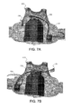
- FlGs. 7A and 7B respectively illustrate right-handed and left-handed layout positions of a power plate, a hub, and a display in relation to the armored vest of FlG. 6.
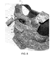
- FIG. 8 illustrates the armored vest of FIG. 6 having a power plate and a display incorporated therewith.
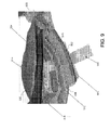
- FIG. 9 illustrates a detailed view of the armored vest of FlG. 6.
- FIG. 1 illustrates a block diagram of an illustrative implementation of a portable power system assembly 100.
- the portable power system assembly 100 may include a power plate 102, a hub 104, a display 106, and peripheral devices 108.
- the power plate 102 serves as a power source and provides electrical power to the peripheral devices 108 via the hub 104.
- Cables such as cables 110 may couple the power plate 102, the hub 104, the display 106, and the peripheral devices 108.
- the cables 110 may include any wire, cable, or other hardware suitable for allowing electrical power and information to be transferred between the power plate 102, the hub 104, the display 106, and the peripheral devices 108.
- any device e.g., the power plate 102, display 106, and/or the peripheral devices 108 may be connected to the hub 104 without identifying or "keying-in" that device.
- the display 106 may be any device suitable for visually conveying dynamic information to a user of the portable power system assembly 100. Functionalities of the display 106 are described in further detail herein.
- the peripheral devices 108 can include any device that uses electrical power to operate. In FIG. 1 , the peripheral devices 108 include a GPS device 112, a radio 114, a battery charger 116, and an MP3 player 118. It is noteworthy that two or more components of the power plate assembly 100 may be integrated as single device. For example, the power plate 102 and the hub 104 may be integrated as a single device having some or all of the functionalities attributed herein to the power plate 102 and the hub 104.
- the power plate 102 may be incorporated in an armored garment (not depicted in FIG. 1 ).
- Such an armored garment may include any wearable item that is protective against ballistic projectiles like bullets, shrapnel, and/or other projectiles. Examples of armored garments may include bullet-resistant vests, armored headwear, lower body armor, and so forth.
- the power plate 102 may be removable or permanently integrated with the armored garment.
- the power plate 102 may be rigid, semi-rigid, partially flexible, or wholly flexible.
- the power plate 102 may have a footprint that corresponds to the footprint of an armored plate 120, as shown in FlG. 1.
- the armored plate 120 may also be incorporated in an armored garment.
- the power plate 102 and the armored plate 120 may be positioned proximally and face-to-face when incorporated in an armored garment.
- the power plate 102 and the armored plate 120 may be positioned at the anterior abdominal area of a vest such that, when worn by a user, the armored plate 120 is disposed between the power plate 102 and the user.
- a second power plate similar to the power plate 102 and a second armored plate similar to the armored plate 120 may be positioned to posterior abdominal area of the vest such that, when worn by the user, the second armored plate is disposed between the second power plate and the user.
- the power plate 102 and constituent components thereof may be military ruggedized for field use, and may be designed to avoid vibrational susceptibility.
- Objects having natural frequencies and/or natural frequency harmonics in the range of about 1500-2000 Hz may be susceptible to vibrations, such as during transportation.
- the armored plate 120 may provide ballistic protection to a user of an armored garment that incorporates the armored plate 120.
- the power plate 102 may enhance the protectiveness of the armored plate 120.
- a ballistic projectile that first strikes the power plate 102 may be decelerated, shattered, or deflected to some degree (e.g., twist), thereby reducing energy transmitted to the armored plate 120.
- the power plate 102 may include one or more cells such as cells 122 (i.e., cells 122a, 122b, 122c, 122d, 122e, 122f, 122g, 122h, 122i, 122j, 122k, 1221, 122m, 122n, 122p). Although sixteen cells—cells 122a-122p—are depicted in FIG. 1 , it should be appreciated that the power plate 102 can include any number of cells.
- the cells 122 may each include an electrochemical cell for electricity storage. lt is noteworthy that the cells 122 may be replaced by other types of electrical storage devices such as capacitive storage devices (not depicted in FIG. 1 ).
- individual ones of the cells 122 may include one or more sensors such as a temperature sensor 124.
- temperature sensors include thermocouples, thermistors, silicon bandgap temperature sensors, resistive thermal devices (RTDs), and so forth.
- the temperature sensor 124 may be communicatively coupled with a processor, which is described further herein.
- the cells 120 may be electrically coupled in any number of configurations. As depicted in FIG. 1 , cells 122a-122d are connected to form string 126a, cells 122e-122h are connected to form string 126b, cells 122i-1221 are connected to form string 126c, and cells 122m-122p are connected to form string 126d.
- the strings 126 may include any number of cells.
- the strings 126 may each include or be associated with one or more overcurrent protection devices (not depicted in FIG. 1 ). Such overcurrent protection devices may be configured to limit current delivered to one of the cells 122 and/or the strings 126. According to some implementations, for example, each of the cells 122 may be associated with a separate overcurrent protection device that may autonomously limit current delivered to a cell associated therewith. Limitations on current may include cutting off current completely, and may be based on any number of factors including individual cell temperature and individual cell capacity.
- the strings 126 may include any configuration such as a rectangular array of cells.
- the cells that are respectively included in each of the strings 126 may be connected in series, in parallel, or in another configuration.
- the strings 126 may be connected in series, in parallel, or in another configuration.
- the strings 126 may be isolated from each other so that they are not interconnected. By segregating the strings 126, performance of the power plate 102 may be maintained, even when one or more of the strings 126 become disabled, such as in the event of ballistic impact on one of the strings 126.
- wires and/or cables routed to the cells 122 may be segregated so as to minimize wire and/or cable failure in the event of ballistic impact on a wire or cable.
- the spatial distribution of cells 122 in the power plate 102 may affect a thermal image of the power plate 102 while in use. For example, if the cells 122 are densely packed, a "hot spot" may be present in the thermal image. In contrast, if the cells 122 are sparsely packed, any potential hot spot may be reduced.
- the power plate 102 may additionally include one or more processors such as processor 128.
- the processor 128 is configured to provide information processing capabilities in the power plate 102.
- the natural frequency of the processor 128 does not have a natural frequency below 2000 Hz when mounted to the power plate 102.
- the processor 128 may include one or more of a digital processor, an analog processor, a digital circuit designed to process information, an analog circuit designed to process information, a state machine, and/or other mechanisms for electronically processing information.
- the processor 128 is shown in FlG. 1 as a single entity, this is for illustrative purposes only. ln some implementations, the processor 128 may include a plurality of processing units. These processing units may be physically located within the same device, or the processor 128 may represent processing functionality of a plurality of devices operating in coordination.
- the processor 128 may be configured to execute one or more computer program modules.
- the one or more computer program modules may include one or more of a temperature module 130, a charge level module 132, a status module 134, a cell disconnect module 136, a charge balancing module 138, a discharge balancing module 140, a status display module 142, and/or other modules.
- the processor 128 may be configured to execute modules 130, 132, 134, 136, 138, 140, and/or 142 by software; hardware; firmware; some combination of software, hardware, and/or firmware; and/or other mechanisms for configuring processing capabilities on the processor 128.
- modules 130, 132,134, 136, 138, 140, and 142 are illustrated in FIG. 1 as being co-located within a single processing unit, in implementations in which the processor 128 includes multiple processing units, one or more of the modules 130, 132, 134, 136, 138, 140, and/or 142 may be located remotely from the other modules.
- the description of the functionality provided by the different modules 130, 132, 134, 136, 138, 140, and/or 142 described below is for illustrative purposes, and is not intended to be limiting, as any of modules 130, 132, 134, 136, 138, 140, and/or 142 may provide more or less functionality than is described.
- modules 130, 132, l34, 136, 138, 140, and/or 142 may be eliminated, and some or all of its functionality may be provided by other ones of modules 130, 132, 134, 136, 138, 140, and/or 142.
- processor 128 may be configured to execute one or more additional modules that may perform some or all of the functionality attributed below to one of modules 130, 132, 134, 136, 138, 140, and/or 142.
- the temperature module 130 may be configured to monitor a temperature of one or more of the cells 122. This monitoring may be performed in conjunction with one or more temperature sensors such as the temperature sensor 124. According to some implementations, the temperature of each of the cells 122 (or a subset thereof) may be individually monitored. Alternatively, the temperatures of the cells 122 may be monitored as an aggregate temperature on a group basis. For example, the average temperature of cells 122e-122h may be monitored as an aggregate temperature associated with string 126b.
- the charge level module 132 may be configured to determine a charge level of one or more of the cells 122.
- Charge level of a cell describes the amount of electrical power contained in or stored by that cell.
- the charge level of each of the cells 122 (or a subset thereof) may be individually determined, in accordance with some implementations.
- the charge levels of the cells 122 may also be determined as an aggregate charge level on a group basis. To illustrate, the aggregate charge level of each of the strings 126 may be determined.
- the status module 134 may be configured to provide status information associated with one or more of the cells 122.
- Status information may be any information associated with one or more of the cells 122.
- the status information may be based at least in part on the temperature and/or the charge level of one or more of the cells 122.
- the status module 134 may also be executed to determine a fault associated with at least one of the cells 122. Such a fault may be based on any failure mode or other state of inoperability of one or more of the cells 122. Additionally, a fault may be based at least in part, for example, on the temperature and/or the charge level being outside of a predetermined range.
- the status information may be provided to other components of the portable power system assembly 100 such as the hub 104, the display 106, and the peripheral devices 108 via the cables 110.
- the cell disconnect module 136 may be configured to disconnect one or more of the cells 122 having a fault associated therewith, such as that determined through execution of the status module 134. By disconnecting a cell having a fault, performance of the portable power system assembly 100 may be enhanced. For example, catastrophic failure of a cell such as an explosion or cell ignition may be prevented. Furthermore, leakage of damaged cells may be halted or minimized. Additionally, by disconnecting a cell having a fault, the remaining cells may be prevented from becoming faulty or otherwise damaged.
- the charge balancing module 138 may be configured to control a charge power level delivered to each of the cells 122, such as while the cells 122 are being charged. Alternatively or additionally, the charge balancing module 138 may be configured to control a charge power level delivered to at least one group of the cells 122, such to the string 126a. Generally, the charge balancing module 138 may balance the charge power levels delivered to the cells 122 by evenly charging the cells 122 to maintain even capacities and temperatures among the cells 122 (e.g., within threshold bands). To control the charge power level, voltage and/or current may be regulated. The charge power level may be controlled based on a number of factors such as cell capacity, cell resistance, cell temperature, and/or any other factors.
- Controlling the charge power level during charging of the cells 122 may extend lifetime and maintain proper performance of the cells 122, as well as prevent overheating. Controlling charge power level of each cell may minimize or greatly reduce charging times. For example, controlling the charge power level may prevent against overcharging where a cell's capacity is exceeded, overvoltage where the cell voltage exceeds an upper design limit, and/or overcurrent where the current delivered to the cell exceeds an upper design limit. To illustrate controlling a charge power level, if one cell is at 80% capacity and the remaining cells are each at 98% capacity, the charge balancing module 138 will prevent excessive current from being provided to the one cell during charging while the capacity of the one cell is brought up to match that of the remaining cells.
- the discharge balancing module 140 may be configured to control a discharge power level drawn from each of the cells 122, such as when electrical power is being provided to the peripheral devices 108. Alternatively or additionally, the discharge balancing module 140 may be configured to control a discharge power level drawn from at least one group of the cells 122, such from the string 126a. Generally, the discharge balancing module 140 may balance the discharge power levels drawn from the cells 122 by evenly discharging the cells 122 to maintain even capacities and temperatures among the cells 122. To control the discharge power level, voltage and/or current may be regulated. The discharge power level may be controlled based on a number of factors such as cell capacity, cell resistance, cell temperature, and/or any other factors.
- Controlling the discharge power level during charging of the cells 122 may extend lifetime and maintain proper performance of the cells 122, as well as prevent safety risks. For example, controlling the discharge power level may prevent against deep discharging where a cell is completely drained or rapid discharges due to shorted circuitry. To illustrate controlling a discharge power level, if the power plate 102 is utilized to provide electrical power to a lamp that is left on for an extended period of time, the discharge balancing module 140 may prevent the cells 122 from becoming completely drained.
- the status display module 142 may be configured to provide status information to a user of the portable power system assembly 100, such as via the display 106. Status information may be provided to the status display module 142 through execution of the status module 134. Status information may include information such as individual cell capacities, aggregate cell capacities, total cell capacity, individual cell temperatures, aggregate cell temperatures, and/or any other information associated with the cells 122. Faults associated with one or more of the cells 122 may also be conveyed to a user though execution of the status display module 142. Additional data may be provided to a user through execution of the status display module 142, such as via the display 106. For example, the number of and identity of the peripheral devices 108 connected to the hub 104 may be indicated on the display 106.
- FIG. 2A illustrates an illustrative implementation of a portable power system assembly 200A.
- the portable power system assembly 200A may include a power plate 202, a power plate 204, a hub 206 and a display 208. Aspects of the power plate 202 and the power plate 204 may be similar to the power plate 102 depicted in FIG. 1 . Additionally, aspects of the hub 206 and the display 208 may be similar, respectively, to the hub 104 and the display 106 depicted in FIG. 1 .
- the power plates 202 and 204 may be detachably connected to the hub 206 by cables 210 and 212, respectively, while the display 208 may be detachably connected to the hub 206 by cable 214.
- Detachable connections may be achieved by connectors coupled to ends of the cables 210, 212, and 214 used in conjunction with ports incorporated in various components of the portable power system assembly 200A such as the hub 206.
- the cables 210, 212, and 214 may facilitate transference of electrical power and information, and be similar to the cables 110 depicted in FIG. 1 .
- FIG. 2B illustrates an illustrative implementation of a portable power system assembly 200B including certain peripheral devices.
- the portable power system assembly 200B may include a GPS device 216, a battery charger 218, a land radio 220, and a multi-band radio 222.
- the portable power system assembly 200B may also include the power plate 202, the power plate 204, the hub 206, the display 208, and the cables 210, 212, and 214, similarly as in portable power system assembly 200A.
- the GPS device 216, the battery charger 218, the land radio 220, and the multi-band radio 222 may be detachably connected to the hub 206 by various cables.
- the power plate 202 and the power plate 204 may provide electrical power to the GPS device 216, the battery charger 218, the land radio 220, and the multi-band radio 222 via the hub 206.
- the power plate 202 and the power plate 204 may be substantially similar. For illustrative purposes, however, constituent components of the power plate 202 may be visible in FlGs. 2A and 2B. More specifically, the power plate 202 may include an array of cells 224, an electronics unit 226, and check valves 228.
- the array of cells 224 may include six rows and four columns of cells.
- the cell included in the array of cells 224 may be grouped electrically as a number of strings.
- the cells in each column in the array of cells 224 may be electrically coupled together as individual strings.
- Each string may be physically isolated from other strings so that, in the event of a catastrophic failure of one string, the other strings may be prevented from damage. For example, if one string is impacted by a ballistic projectile causing one or more cells in that string to rupture and ignite, resultant gases or heat may be substantially isolated from the other strings, which may remain operable.
- the electronics unit 226 may include electronic components suitable for transferring electrical power between the power plate 202 to other components of the portable power system assembly 200A and/or the portable power system assembly 200B.
- the electronics unit 226 may also facilitate the transfer of information associated with the array of cells 224 to other components of the portable power system assembly 200A and/or the portable power system assembly 200B.
- the electronics unit 226 may include one or more processors such as the processor 128.
- the check valves 228 may provide controlled pressure release in the event of a catastrophic failure of one or more cells included in a string. For example, if one string is impacted by a ballistic projectile causing one or more cells in that string to rupture and/or ignite, pressure from resultant gases may be released by one or more of the check valves 228. After pressure is released, the check valves 228 may reseal to maintain physical isolation of the strings of cells. By the check valves 228 resealing, the cells 122 may maintain compatibility with adverse environmental conditions such as marine conditions.
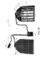
- FIG. 3A illustrates a power plate 302 connected to a cable connector 304, according to an illustrative implementation. Aspects of the power plate 302 may be similar to the power plate 102 depicted in FIG. 1 .
- the cable connector 304 may be utilized to detachably connect cable 306 to the power plate 302.
- the cable 306 may facilitate transfer of electrical power and information between the power plate 302 and other components of a portable power system assembly such as portable power system assembly 200B.
- FIG. 3B illustrates the power plate 302 disconnected from the cable connector 304.
- a port 308 integral with the power plate 302 may receive the cable connector 304.
- the cable connector 304 and/or the port 308 may include a number of pins for electrical power and information transfer.
- FIG. 4A illustrates a hub 402 according to an illustrative implementation. Aspects of the hub 402 may be similar to the hub 104 depicted in FIG. 1 .
- the hub 402 may include a number of ports such as port 404.
- the port 404 may receive a cable connector such as cable connector 406 in order to detachably connect a cable such as cable 408 to the hub.
- the hub 402 may form an electrical and informational interface between one or more power plates (e.g., the power plate 102 depicted in FIG. 1 ) and one or more peripheral devices (e.g., the peripheral devices 108 depicted in FIG. 1 ), such that electrical power and information may flow between the one or more power plates and the one or more peripheral devices.
- power plates e.g., the power plate 102 depicted in FIG. 1
- peripheral devices e.g., the peripheral devices 108 depicted in FIG. 1
- FIG. 4B illustrates the hub 402 with a controller card 410 removed.
- the controller card 410 may be inserted and ejected from card slot 412.
- the controller card 410 may be replaced, for example, to facilitate hardware upgrades and/or repairs.
- the controller card may include one or more processors such as processors 414 and 416.
- the processors 414 and 416 are configured to provide information processing capabilities in the hub 402.
- each of the processors 414 and 416 may include one or more of a digital processor, an analog processor, a digital circuit designed to process information, an analog circuit designed to process information, a state machine, and/or other mechanisms for electronically processing information.
- the processors 414 and 416 are shown in FIG. 4B as two individual entities, this is for illustrative purposes only. ln some implementations, each of the processors 414 and 416 may include a plurality of processing units. These processing units may be physically located within the same device, or each of the processors 414 and 416 may represent processing functionality of a plurality of devices operating in coordination.
- the processors 414 and 416 may each be configured to execute one or more computer program modules. For example, one or both of the processors 414 and 416 may execute a computer program module to identify peripheral devices and power plates that are connected to the hub 402
- FIG. 5 illustrates an illustrative implementation of a display 502. Aspects of the display 502 may be similar to the display 106 depicted in FIG. 1 .
- the display 502 may visually convey information to a user such as status information associated with one or more power plates (e.g., the power plate 102 depicted in FIG. 1 ).
- the display 502 may be dual sided. That is, the display 502 may be capable of visually conveying dynamic information to a user from both sides (front and back) of the display 502. Being dual sided may allow for ambidextrous placement of the display 502.
- FIG. 6 illustrates an illustrative implementation of an armored vest 600, with which power plates (e.g., the power plate 102 depicted in FIG. 1 ) may be incorporated.
- the armored vest 600 may also incorporate one or more armored plates such as the armored plate 120 depicted in FIG. 1 .
- a power plate and/or an armored plate may be positioned in the anterior abdominal area of the armored vest 600.
- a power plate and/or an armored plate may be positioned in the posterior abdominal area of the armored vest 600.
- the armored vest 600 may be worn, for example, by military and/or law enforcement personnel to project against ballistic projectiles, shrapnel and/or other projectiles.
- the armored vest 600 is described in further detail in connection with FlGs. 7A, 7B, 8, and 9.
- FlGs. 7A and 7B respectively illustrate right-handed and left-handed layout positions of a power plate 702, a hub 704, and a display 706 in relation to the armored vest 600. More specifically, the power plate 702, the hub 704, and the display 706 are overlaid on the armored vest 600 to describe illustrative positions of the power plate 702, the hub 704, and the display 706 when incorporated with the armored vest 600.
- the layout positions illustrated in FlGs. 7A and 7B are illustrative of illustrative positions of the power plate 702, the hub 704, and the display 706, and do not encompass all possible positions. Aspects of the power plate 702, the hub 704, and the display 706 may be similar, respectively, to the power plate 102, the hub 104, and the display 106 depicted in FIG. 1 .
- the power plate 702 is positioned at the anterior abdominal area of the armored vest 600.
- the power plate 702 may be aligned with an armored plate when incorporated with the armored vest 600, such that the power plate 702 and the armored plate are positioned proximally and face-to-face.
- the hub 704 is positioned at the left-lateral waist area of the armored vest 600
- the hub 704 is positioned at the right-lateral waist area of the armored vest 600.
- the display 706, in FIG. 7A is positioned at the right-chest area of the armored vest 600.
- the display 706 is positioned at the left-chest area of the armored vest 600.
- the ambidextrous nature of the layout positions illustrated in FlGs. 7A and 7B demonstrate convenient positioned for both right-handed and left-handed users.
- FIG. 8 illustrates the armored vest 600 having a power plate 802 and a display 804 incorporated therewith. Aspects of the power plate 802 and the display 804 may be similar, respectively, to the power plate 102 and the display 106 depicted in FIG. 1 .
- the power plate 802 may be incorporated with the armored vest 600 in that the power plate 802 may be held within a sleeve integral with the armored vest 600.
- Various sleeves of the armored vest 600 are described further in connection with FIG. 9 .
- the display 804 may be connected to the power plate 802 via the cable 806 and, for example, a hub (not depicted in FIG. 8 ) such as the hub 104 of FIG. 1 .
- the sleeve 808 may secure the display 804 while the 600 is worn by a user.
- the sleeve 808 may include a window 810 to allow information to be visually conveyed from the display 804 to the user while the display 804 is inserted in the sleeve 808.
- FIG. 9 illustrates a detailed view of the armored vest 600. More specifically, FIG. 9 shows the bottom edge of the anterior portion of the armored vest 600. According to illustrative implementations, the posterior portion (not depicted in FIG. 9 ) of the armored vest 600 may be substantially similar, in design and/or functionality, to anterior portion of the armored vest 600. ln FIG. 9 , the armored vest 600 may be oriented such that the front-side 902 is at the bottom and the back-side 904 is at the top. When the armored vest 600 is worn a user, the back-side 904 may be closest to the user.
- a power plate 906 is shown inserted into power plate sleeve 908.
- the power plate 906 may be secured in the power plate sleeve 908 using a power plate extraction strap 910, which may include Velcro and/or other fasteners.
- the power plate 906 may be secured in the power plate sleeve 908 using a pouch (not depicted in FIG. 9 ) that suspends the power plate 906 in the power plate sleeve 908.
- An armored plate 912 is shown inserted into armored plate sleeve 914.
- the armored plate 912 may be secured in the armored plate sleeve 914 using an armored plate extraction strap 916.
- the armored plate 912 may be secured in the armored plate sleeve 914 using a pouch (not depicted in FIG. 9 ) that suspends the armored plate 912 in the armored plate sleeve 914.
- a pouch not depicted in FIG. 9
- Aspects of the power plate 906 and the armored plate sleeve 914 may be similar, respectively to the power plate 102 and the armored plate 120 of FIG. 1 .
- a soft armor layer 918 is shown inserted into a soft armor layer sleeve 920. The soft armor layer 918 may provide increased ballistic protection to a user while the armored vest 600 is worn.
- the power plate 906, the armored plate 912, and/or the soft armor layer 918 may be removed and/or replaced through the bottom of the armored vest 600. Removal of the power plate 906, the armored plate 912, and/or the soft armor layer 918 through the bottom of the armored vest 600 may be advantageous, relative to removal through the top of the vest, for example, when a user is in a prone position where the user's chin might otherwise hamper removal.
- the terms “comprises,” “comprising,” “includes,” “including,” “has,” “having” or any other variation thereof, are intended to cover a non-exclusive inclusion.
- a process, method, article, or apparatus that comprises a list of elements is not necessarily limited to only those elements but may include other elements not expressly listed or inherent to such process, method, article, or apparatus.
- “or” refers to an inclusive or and not to an exclusive or. For example, a condition A or B is satisfied by any one of the following: A is true (or present) and B is false (or not present), A is false (or not present) and B is true (or present), and both A and B are true (or present).
Landscapes
- Chemical & Material Sciences (AREA)
- Chemical Kinetics & Catalysis (AREA)
- Electrochemistry (AREA)
- General Chemical & Material Sciences (AREA)
- Engineering & Computer Science (AREA)
- Manufacturing & Machinery (AREA)
- Life Sciences & Earth Sciences (AREA)
- Biophysics (AREA)
- Computer Hardware Design (AREA)
- General Engineering & Computer Science (AREA)
- Charge And Discharge Circuits For Batteries Or The Like (AREA)
- Secondary Cells (AREA)
- Battery Mounting, Suspending (AREA)
Applications Claiming Priority (1)
| Application Number | Priority Date | Filing Date | Title |
|---|---|---|---|
| US12/688,770 US8502506B2 (en) | 2010-01-15 | 2010-01-15 | Portable electrical power source for incorporation with an armored garment |
Publications (2)
| Publication Number | Publication Date |
|---|---|
| EP2345867A2 true EP2345867A2 (de) | 2011-07-20 |
| EP2345867A3 EP2345867A3 (de) | 2014-10-29 |
Family
ID=43902642
Family Applications (1)
| Application Number | Title | Priority Date | Filing Date |
|---|---|---|---|
| EP11151016.0A Withdrawn EP2345867A3 (de) | 2010-01-15 | 2011-01-14 | Körperschutzbekleidung mit Bereitstellung von elektrischem Strom |
Country Status (5)
| Country | Link |
|---|---|
| US (1) | US8502506B2 (de) |
| EP (1) | EP2345867A3 (de) |
| AU (1) | AU2011200068B2 (de) |
| CA (1) | CA2727364A1 (de) |
| NZ (1) | NZ590369A (de) |
Cited By (1)
| Publication number | Priority date | Publication date | Assignee | Title |
|---|---|---|---|---|
| EP3785431A4 (de) * | 2018-04-27 | 2022-01-19 | Lat Enterprises Inc. d/b/a Medipak Energy System | Persönliches taktisches system und netzwerk |
Families Citing this family (32)
| Publication number | Priority date | Publication date | Assignee | Title |
|---|---|---|---|---|
| US20110108538A1 (en) | 2009-11-06 | 2011-05-12 | Rick Gray | Electrically heated garment |
| US20130037531A1 (en) | 2009-11-06 | 2013-02-14 | Rick Gray | Electrically heated garment |
| WO2012027824A1 (en) * | 2010-09-03 | 2012-03-08 | Cynetic Designs Ltd. | A system for inductive power transmission in a garment |
| US20140191706A1 (en) * | 2013-01-08 | 2014-07-10 | Mario Maese | Article of Clothing and Related Methods |
| US11302987B2 (en) | 2014-10-16 | 2022-04-12 | Lat Enterprises | Material for dissipating heat from and/or reducing heat signature of electronic devices and clothing |
| US11462649B2 (en) | 2014-10-16 | 2022-10-04 | Lat Enterprises, Inc. | Portable power case |
| US10727457B2 (en) | 2014-01-15 | 2020-07-28 | Lat Enterprises, Inc. | System for supplying power to a portable battery using at least one solar panel |
| US10531590B2 (en) | 2014-10-16 | 2020-01-07 | Lat Enterprises, Inc. | System for supplying power to at least one power distribution and data hub using a portable battery pack |
| US12088244B2 (en) * | 2014-01-15 | 2024-09-10 | Lat Enterprises, Inc. | System for supplying power to at least one power consuming device using rechargeable battery |
| US11996803B2 (en) | 2014-01-15 | 2024-05-28 | Lat Enterprises, Inc. | Foldable solar panel |
| US11025075B2 (en) | 2014-10-16 | 2021-06-01 | Lat Enterprises, Inc. | Portable power case with heat-resistant material |
| US12119785B2 (en) | 2014-01-15 | 2024-10-15 | Lat Enterprises, Inc. | Dual voltage solar panel |
| US10944140B2 (en) | 2014-01-15 | 2021-03-09 | Lat Enterprises, Inc. | Wearable and replaceable pouch or skin for holding a portable battery pack |
| US11876354B2 (en) * | 2014-01-15 | 2024-01-16 | Lat Enterprises, Inc. | Wearable and replaceable pouch or skin for holding a portable battery pack |
| US10476054B2 (en) * | 2014-10-16 | 2019-11-12 | Lat Enterprises, Inc. | Portable battery pack comprising a battery enclosed by a wearable and replaceable pouch or skin |
| US12368409B1 (en) | 2014-01-15 | 2025-07-22 | Lat Enterprises, Inc. | Foldable solar panel |
| US10991992B2 (en) | 2014-01-15 | 2021-04-27 | Lat Enterprises, Inc. | System for supplying power to a portable battery using at least one solar panel |
| US11304500B2 (en) | 2014-01-15 | 2022-04-19 | Lat Enterprises, Inc. | Wearable and replaceable pouch or skin for holding a portable battery pack |
| USD808616S1 (en) | 2014-02-28 | 2018-01-30 | Milwaukee Electric Tool Corporation | Single control button for an article of clothing |
| US12407175B2 (en) | 2014-10-16 | 2025-09-02 | Lat Enterprises, Inc. | Wearable and lightweight portable power case |
| US11025076B2 (en) | 2014-10-16 | 2021-06-01 | Lat Enterprises, Inc. | Portable power case with lithium iron phosphate battery |
| US10616534B2 (en) | 2014-10-16 | 2020-04-07 | Lat Enterprises, Inc. | Personal tactical system and network |
| US11033059B2 (en) | 2014-11-06 | 2021-06-15 | Milwaukee Electric Tool Corporation | Article of clothing with control button |
| USD794281S1 (en) | 2015-10-09 | 2017-08-15 | Milwaukee Electric Tool Corporation | Garment |
| USD787160S1 (en) | 2015-10-09 | 2017-05-23 | Milwaukee Electric Tool Corporation | Garment |
| USD808125S1 (en) | 2015-10-09 | 2018-01-23 | Milwaukee Electric Tool Corporation | Garment |
| USD799161S1 (en) | 2015-10-09 | 2017-10-10 | Milwaukee Electric Tool Corporation | Garment |
| US11754375B1 (en) * | 2020-10-29 | 2023-09-12 | Cornerstone Research Group, Inc. | Apparatuses and wearable armor systems including electrical sources |
| US11744298B2 (en) | 2020-12-04 | 2023-09-05 | Milwaukee Electric Tool Corporation | Electrically heated garment with pass-through battery pocket |
| US20220285970A1 (en) * | 2021-03-05 | 2022-09-08 | RHiot, Inc. | Managing power between wearable devices |
| USD1020226S1 (en) | 2021-10-21 | 2024-04-02 | Milwaukee Electric Tool Corporation | Control button for heated garment |
| US20230336029A1 (en) * | 2022-04-14 | 2023-10-19 | Cynetic Designs Ltd. | Wearable battery charging cradle |
Family Cites Families (78)
| Publication number | Priority date | Publication date | Assignee | Title |
|---|---|---|---|---|
| US3331083A (en) | 1966-02-23 | 1967-07-18 | Mildred K Holly | Leg protective armor system |
| US3452362A (en) | 1967-04-12 | 1969-07-01 | Us Army | Torso armor carrier |
| US3557384A (en) | 1969-02-24 | 1971-01-26 | Us Army | Variable infantry armor system |
| US3559210A (en) | 1969-05-16 | 1971-02-02 | John V E Hansen | Composite ceramic body armor or shield |
| BE792805A (fr) | 1971-12-17 | 1973-03-30 | Feldmuehle Anlagen Prod | Vetement de protection contre les projectiles a forte energie cinetiqu |
| US3832266A (en) | 1972-12-05 | 1974-08-27 | Us Army | Fiberglass laminate backed ceramic armor |
| US3873998A (en) | 1974-03-26 | 1975-04-01 | Us Army | Body armor system |
| US3858241A (en) | 1974-03-26 | 1975-01-07 | Us Army | Shock absorbent collar for armor plate |
| US4292882A (en) | 1977-06-07 | 1981-10-06 | Clausen Carol W | Armor comprising a plurality of loosely related sheets in association with a frontal sheet comprising metal abrading particles |
| US4352316A (en) | 1978-06-30 | 1982-10-05 | Medlin Richard C | Lightweight armored vehicle and method of making same using woven polyester glass protective sheets |
| US4530111A (en) | 1983-08-26 | 1985-07-23 | Multi-Tech Corporation | Body armor |
| US4633756A (en) | 1984-05-21 | 1987-01-06 | Rudoi Boris L | Bullet proof armor shield |
| US4613535A (en) | 1985-02-28 | 1986-09-23 | Allied Corporation | Complex composite article having improved impact resistance |
| US4857119A (en) | 1988-03-01 | 1989-08-15 | General Dynamics Lands Systems, Inc. | Case-Hardened plate armor and method of making |
| US4879165A (en) | 1988-06-20 | 1989-11-07 | Smith W Novis | Lightweight armor |
| US4923728A (en) | 1988-11-07 | 1990-05-08 | Titan Corporation | Protective armor and method of assembly |
| US4987033A (en) | 1988-12-20 | 1991-01-22 | Dynamet Technology, Inc. | Impact resistant clad composite armor and method for forming such armor |
| FR2655413B1 (fr) | 1989-12-06 | 1994-06-03 | Europ Propulsion | Blindage de protection balistique. |
| US5007326A (en) | 1990-01-16 | 1991-04-16 | The United States Of America As Represented By The Secretary Of The Army | Cast single plate P900 armor |
| US5060314A (en) | 1990-04-03 | 1991-10-29 | The United States Of America As Represented By The Secretary Of The Navy | Multi-mission ballistic resistant jacket |
| GB9016915D0 (en) | 1990-08-01 | 1990-09-12 | Secr Defence | Protective clothing |
| US5185195A (en) | 1990-11-19 | 1993-02-09 | Allied-Signal Inc. | Constructions having improved penetration resistance |
| US5196252A (en) | 1990-11-19 | 1993-03-23 | Allied-Signal | Ballistic resistant fabric articles |
| NL9002590A (nl) | 1990-11-28 | 1992-06-16 | Stamicarbon | Meerlaagse, anti-ballistische structuur. |
| WO1992020520A1 (en) | 1991-05-24 | 1992-11-26 | Allied-Signal Inc. | Flexible composites having rigid isolated panels and articles fabricated from same |
| US5443917A (en) | 1991-05-24 | 1995-08-22 | Gte Products Corporation | Ceramic armor |
| JPH08500424A (ja) | 1991-11-23 | 1996-01-16 | サックス,マイケル | よろい |
| US5349893A (en) | 1992-02-20 | 1994-09-27 | Dunn Eric S | Impact absorbing armor |
| GB9316172D0 (en) | 1993-08-04 | 1993-09-22 | Sacks Michael | Protective shield |
| US5465424A (en) | 1993-09-21 | 1995-11-14 | Tipperary Sport Products, Inc. | Body protector |
| US5437905A (en) | 1994-05-17 | 1995-08-01 | Park; Andrew D. | Ballistic laminate structure in sheet form |
| US5935678A (en) | 1994-05-17 | 1999-08-10 | Park; Andrew D. | Ballistic laminate structure in sheet form |
| US5500952A (en) | 1994-10-28 | 1996-03-26 | Keyes; Marshall J. | Hip inflatable protection device |
| US5831198A (en) | 1996-01-22 | 1998-11-03 | Raytheon Company | Modular integrated wire harness for manportable applications |
| IT1282143B1 (it) | 1996-04-29 | 1998-03-12 | Citterio Flli Spa | Tessuto multiassiale multistrato, atto a essere utilizzato per impieghi balistici e procedimento per realizzare il suddetto tessuto |
| US5906873A (en) | 1996-07-03 | 1999-05-25 | Higher Dimension Medical, Inc. | Puncture, pierce, and cut resistant fabric |
| US5960470A (en) | 1996-08-02 | 1999-10-05 | Second Chance Body Armor, Inc. | Puncture resistant protective garment and method for making same |
| US5771489A (en) | 1996-11-12 | 1998-06-30 | Titan Corporation | Penetration-resistant hinge and flexible armor incorporating same |
| US5824940A (en) | 1997-01-27 | 1998-10-20 | Alfred University | Ceramic bullet-proof fabric |
| US6009789A (en) | 1997-05-01 | 2000-01-04 | Simula Inc. | Ceramic tile armor with enhanced joint and edge protection |
| US5970843A (en) | 1997-05-12 | 1999-10-26 | Northtrop Grumman Corporation | Fiber reinforced ceramic matrix composite armor |
| US6029269A (en) | 1997-12-22 | 2000-02-29 | Boeing North American, Inc. | Ballistic-resistant helmet and method for producing the same |
| US6026510A (en) | 1997-12-31 | 2000-02-22 | Kocher; Robert William | Bullet deflection, fighting position body armor |
| JPH11266543A (ja) * | 1998-03-18 | 1999-09-28 | Makita Corp | 電動工具充電システム |
| EP0967453A1 (de) | 1998-06-25 | 1999-12-29 | Armortec Incorporated | Flexibles, schlagbeständiges Material |
| EP1135827A1 (de) | 1998-10-16 | 2001-09-26 | Paratek Microwave, Inc. | Spannungsgesteuerte dielektrische mehrschichtmaterialien für mikrowellenanwendungen |
| US6035438A (en) | 1999-04-30 | 2000-03-14 | Neal; Murray L. | Method and apparatus for defeating ballistic projectiles |
| US6510777B2 (en) | 1999-04-30 | 2003-01-28 | Pinnacle Armor, Llc | Encapsulated imbricated armor system |
| DE60009520T2 (de) | 1999-09-14 | 2005-03-03 | Paratek Microwave, Inc. | Reihengespeiste phasenarrayantennen mit dielektrischen phasenschiebern |
| US6408733B1 (en) | 2000-02-14 | 2002-06-25 | William J. Perciballi | Ceramic armor apparatus for multiple bullet protection |
| US6985050B2 (en) | 2000-04-20 | 2006-01-10 | Paratek Microwave, Inc. | Waveguide-finline tunable phase shifter |
| US7056468B2 (en) | 2000-06-15 | 2006-06-06 | Paratek Microwave, Inc. | Method for producing low-loss tunable ceramic composites with improved breakdown strengths |
| WO2001099224A1 (en) | 2000-06-16 | 2001-12-27 | Paratek Microwave, Inc. | Electronically tunable dielectric composite thick films |
| US6544913B2 (en) | 2001-01-19 | 2003-04-08 | Agency For Defense Development | Alumina-silica ceramic |
| US6718861B1 (en) | 2001-06-22 | 2004-04-13 | Southwest Research Institute | Momentum trap ballistic armor system |
| US6389594B1 (en) | 2001-08-30 | 2002-05-21 | Israel Military Industries Ltd. | Anti-ballistic ceramic articles |
| US6846758B2 (en) | 2002-04-19 | 2005-01-25 | Honeywell International Inc. | Ballistic fabric laminates |
| US6841492B2 (en) | 2002-06-07 | 2005-01-11 | Honeywell International Inc. | Bi-directional and multi-axial fabrics and fabric composites |
| US20060252325A1 (en) | 2002-10-17 | 2006-11-09 | Mineaki Matsumura | Protection product |
| US7714538B2 (en) * | 2002-11-22 | 2010-05-11 | Milwaukee Electric Tool Corporation | Battery pack |
| EP1629247B1 (de) | 2003-05-29 | 2008-10-15 | Barrday, Inc. | Einzigartige ballistische anordnung |
| WO2004109214A2 (en) | 2003-06-04 | 2004-12-16 | Magshield Technologies, Llc | Bullet-resistant hand-held defensive object |
| EP1678461A4 (de) | 2003-10-28 | 2010-09-29 | Strike Face Technology Inc | Keramikpanzerung und herstellungsverfahren |
| US7067031B2 (en) | 2003-12-03 | 2006-06-27 | Dew Engineering And Development Limited | Process for making a ceramic armor plate |
| WO2005110299A2 (en) * | 2004-05-07 | 2005-11-24 | Ardica Technologies, Inc. | A method of controlling body temperature with an electrochemical device while providing on-demand power to an electrical device |
| GB2415602A (en) | 2004-07-02 | 2006-01-04 | Thales Uk Plc | Armour |
| ITMO20040334A1 (it) | 2004-12-17 | 2005-03-17 | Fabio Massimo Marchesi | Abbigliamento dotato di propieta' antiproiettile e anicoltello. |
| US7222562B2 (en) | 2005-08-30 | 2007-05-29 | Smiley Gary Leroy | Electromagnetic vehicle cover |
| US7404352B1 (en) | 2006-01-11 | 2008-07-29 | Joseph Malewich | Personal armor |
| US8397312B1 (en) * | 2006-03-02 | 2013-03-19 | Lineweight Llc | Supplemental body armor component |
| WO2008054358A2 (en) | 2006-06-09 | 2008-05-08 | First Choice Armor And Equipment Company | Protective garment having a quick release system |
| WO2008023199A1 (en) * | 2006-08-24 | 2008-02-28 | Absl Power Solutions Limited | Conformable battery packs |
| CN101641565A (zh) * | 2007-03-22 | 2010-02-03 | 矿井安全装置公司 | 冲击传感器和包括冲击传感器的系统 |
| US20100115680A1 (en) * | 2007-04-10 | 2010-05-13 | Thomas Toby D | Garment Including Electrical Energy Storage Unit |
| US20080307553A1 (en) | 2007-06-12 | 2008-12-18 | Energy Science Llc | Method And Apparatus For Protecting Against Ballistic Projectiles |
| WO2010037171A1 (en) * | 2008-09-30 | 2010-04-08 | Tectonica Australia Pty Ltd | Personal portable power distribution apparatus |
| US7805767B2 (en) | 2008-10-06 | 2010-10-05 | Bae Systems Land & Armaments | Body armor plate having integrated electronics modules |
| DE102009042455B4 (de) * | 2009-09-23 | 2016-03-17 | Hexonia Gmbh | Tragsystem mit einer ballistischen Schutzweste |
-
2010
- 2010-01-15 US US12/688,770 patent/US8502506B2/en not_active Expired - Fee Related
-
2011
- 2011-01-07 NZ NZ590369A patent/NZ590369A/en not_active IP Right Cessation
- 2011-01-07 AU AU2011200068A patent/AU2011200068B2/en not_active Ceased
- 2011-01-11 CA CA2727364A patent/CA2727364A1/en not_active Abandoned
- 2011-01-14 EP EP11151016.0A patent/EP2345867A3/de not_active Withdrawn
Non-Patent Citations (1)
| Title |
|---|
| None |
Cited By (1)
| Publication number | Priority date | Publication date | Assignee | Title |
|---|---|---|---|---|
| EP3785431A4 (de) * | 2018-04-27 | 2022-01-19 | Lat Enterprises Inc. d/b/a Medipak Energy System | Persönliches taktisches system und netzwerk |
Also Published As
| Publication number | Publication date |
|---|---|
| AU2011200068A1 (en) | 2011-09-22 |
| CA2727364A1 (en) | 2011-07-15 |
| US8502506B2 (en) | 2013-08-06 |
| AU2011200068B2 (en) | 2015-04-30 |
| NZ590369A (en) | 2012-02-24 |
| US20110173731A1 (en) | 2011-07-21 |
| EP2345867A3 (de) | 2014-10-29 |
Similar Documents
| Publication | Publication Date | Title |
|---|---|---|
| AU2011200068B2 (en) | Portable electrical power source for incorporation with an armoured garment | |
| US8927137B2 (en) | Fail safe damage resistant battery matrix | |
| US12611026B2 (en) | Wearable and replaceable pouch or skin for holding a portable battery pack | |
| US12615880B2 (en) | Portable power case | |
| US11860236B2 (en) | Device for providing output power to electrical equipment | |
| US10461289B2 (en) | Portable battery pack comprising a battery enclosed by a wearable and replaceable pouch or skin | |
| US9564761B2 (en) | Conformable wearable battery with removable command module | |
| US20100115680A1 (en) | Garment Including Electrical Energy Storage Unit | |
| EP2866598B1 (de) | Für elektronik konfigurierter helm | |
| WO2008023199A1 (en) | Conformable battery packs | |
| WO2007056202A3 (en) | Lithium polymer battery powered intravenous fluid warmer | |
| US20190173138A1 (en) | Battery module and surfing apparatus having the same | |
| KR102766496B1 (ko) | 연쇄발화 방지를 위한 에너지 드레인 저항체를 구비한 배터리 팩 | |
| EP3160002B1 (de) | Aktiv ausgleichendes ladegerät | |
| EP3273521B1 (de) | Gestufte batterie | |
| US20130088185A1 (en) | Method And Apparatus For A Battery Docking Connector Having Reserve Power For Hot Battery Swap | |
| CN204541108U (zh) | 穿戴式电池包收容装置及穿戴式电池包系统 | |
| CA2810287A1 (en) | Bulletproof cooling vest | |
| CN204541109U (zh) | 穿戴式电池包收容装置及穿戴式电池包系统 | |
| CN107785964A (zh) | 一种锂电池充放电温度安全控制系统 | |
| US20230216337A1 (en) | Stacked power supply system | |
| US20250364662A1 (en) | Flexible battery system for curved surface applications | |
| US20250149721A1 (en) | Battery Pack, Electronic System, and Article of Personal Protective Equipment | |
| US20100154092A1 (en) | Ballistics vest pad cover | |
| TW201710827A (zh) | 配置以用於不同電池類型之電池架及系統 |
Legal Events
| Date | Code | Title | Description |
|---|---|---|---|
| PUAI | Public reference made under article 153(3) epc to a published international application that has entered the european phase |
Free format text: ORIGINAL CODE: 0009012 |
|
| AK | Designated contracting states |
Kind code of ref document: A2 Designated state(s): AL AT BE BG CH CY CZ DE DK EE ES FI FR GB GR HR HU IE IS IT LI LT LU LV MC MK MT NL NO PL PT RO RS SE SI SK SM TR |
|
| AX | Request for extension of the european patent |
Extension state: BA ME |
|
| RIC1 | Information provided on ipc code assigned before grant |
Ipc: F41H 1/02 20060101AFI20140430BHEP Ipc: H01M 10/00 20060101ALI20140430BHEP |
|
| PUAL | Search report despatched |
Free format text: ORIGINAL CODE: 0009013 |
|
| AK | Designated contracting states |
Kind code of ref document: A3 Designated state(s): AL AT BE BG CH CY CZ DE DK EE ES FI FR GB GR HR HU IE IS IT LI LT LU LV MC MK MT NL NO PL PT RO RS SE SI SK SM TR |
|
| AX | Request for extension of the european patent |
Extension state: BA ME |
|
| RIC1 | Information provided on ipc code assigned before grant |
Ipc: H01M 2/10 20060101ALI20140919BHEP Ipc: H01M 10/48 20060101ALI20140919BHEP Ipc: F41H 1/02 20060101AFI20140919BHEP Ipc: H01M 10/42 20060101ALN20140919BHEP Ipc: H01M 10/44 20060101ALI20140919BHEP |
|
| 17P | Request for examination filed |
Effective date: 20150317 |
|
| RBV | Designated contracting states (corrected) |
Designated state(s): AL AT BE BG CH CY CZ DE DK EE ES FI FR GB GR HR HU IE IS IT LI LT LU LV MC MK MT NL NO PL PT RO RS SE SI SK SM TR |
|
| STAA | Information on the status of an ep patent application or granted ep patent |
Free format text: STATUS: THE APPLICATION IS DEEMED TO BE WITHDRAWN |
|
| 18D | Application deemed to be withdrawn |
Effective date: 20160802 |