EP2345903A1 - Procédé et dispositif pour estimer la durée de vie restante d'une bobine - Google Patents
Procédé et dispositif pour estimer la durée de vie restante d'une bobine Download PDFInfo
- Publication number
- EP2345903A1 EP2345903A1 EP11162776A EP11162776A EP2345903A1 EP 2345903 A1 EP2345903 A1 EP 2345903A1 EP 11162776 A EP11162776 A EP 11162776A EP 11162776 A EP11162776 A EP 11162776A EP 2345903 A1 EP2345903 A1 EP 2345903A1
- Authority
- EP
- European Patent Office
- Prior art keywords
- breakdown voltage
- coil
- internal electrode
- insulating layer
- potential
- Prior art date
- Legal status (The legal status is an assumption and is not a legal conclusion. Google has not performed a legal analysis and makes no representation as to the accuracy of the status listed.)
- Granted
Links
Images







Classifications
-
- H—ELECTRICITY
- H02—GENERATION; CONVERSION OR DISTRIBUTION OF ELECTRIC POWER
- H02K—DYNAMO-ELECTRIC MACHINES
- H02K15/00—Processes or apparatus specially adapted for manufacturing, assembling, maintaining or repairing of dynamo-electric machines
-
- H—ELECTRICITY
- H02—GENERATION; CONVERSION OR DISTRIBUTION OF ELECTRIC POWER
- H02K—DYNAMO-ELECTRIC MACHINES
- H02K11/00—Structural association of dynamo-electric machines with electric components or with devices for shielding, monitoring or protection
- H02K11/30—Structural association with control circuits or drive circuits
- H02K11/35—Devices for recording or transmitting machine parameters, e.g. memory chips or radio transmitters for diagnosis
-
- H—ELECTRICITY
- H02—GENERATION; CONVERSION OR DISTRIBUTION OF ELECTRIC POWER
- H02K—DYNAMO-ELECTRIC MACHINES
- H02K11/00—Structural association of dynamo-electric machines with electric components or with devices for shielding, monitoring or protection
- H02K11/20—Structural association of dynamo-electric machines with electric components or with devices for shielding, monitoring or protection for measuring, monitoring, testing, protecting or switching
-
- H—ELECTRICITY
- H02—GENERATION; CONVERSION OR DISTRIBUTION OF ELECTRIC POWER
- H02K—DYNAMO-ELECTRIC MACHINES
- H02K11/00—Structural association of dynamo-electric machines with electric components or with devices for shielding, monitoring or protection
- H02K11/30—Structural association with control circuits or drive circuits
- H02K11/33—Drive circuits, e.g. power electronics
-
- G—PHYSICS
- G01—MEASURING; TESTING
- G01R—MEASURING ELECTRIC VARIABLES; MEASURING MAGNETIC VARIABLES
- G01R31/00—Arrangements for testing electric properties; Arrangements for locating electric faults; Arrangements for electrical testing characterised by what is being tested not provided for elsewhere
- G01R31/12—Testing dielectric strength or breakdown voltage ; Testing or monitoring effectiveness or level of insulation, e.g. of a cable or of an apparatus, for example using partial discharge measurements; Electrostatic testing
- G01R31/1227—Testing dielectric strength or breakdown voltage ; Testing or monitoring effectiveness or level of insulation, e.g. of a cable or of an apparatus, for example using partial discharge measurements; Electrostatic testing of components, parts or materials
- G01R31/1263—Testing dielectric strength or breakdown voltage ; Testing or monitoring effectiveness or level of insulation, e.g. of a cable or of an apparatus, for example using partial discharge measurements; Electrostatic testing of components, parts or materials of solid or fluid materials, e.g. insulation films, bulk material; of semiconductors or LV electronic components or parts; of cable, line or wire insulation
- G01R31/1272—Testing dielectric strength or breakdown voltage ; Testing or monitoring effectiveness or level of insulation, e.g. of a cable or of an apparatus, for example using partial discharge measurements; Electrostatic testing of components, parts or materials of solid or fluid materials, e.g. insulation films, bulk material; of semiconductors or LV electronic components or parts; of cable, line or wire insulation of cable, line or wire insulation, e.g. using partial discharge measurements
-
- G—PHYSICS
- G01—MEASURING; TESTING
- G01R—MEASURING ELECTRIC VARIABLES; MEASURING MAGNETIC VARIABLES
- G01R31/00—Arrangements for testing electric properties; Arrangements for locating electric faults; Arrangements for electrical testing characterised by what is being tested not provided for elsewhere
- G01R31/34—Testing dynamo-electric machines
- G01R31/346—Testing of armature or field windings
-
- G—PHYSICS
- G01—MEASURING; TESTING
- G01R—MEASURING ELECTRIC VARIABLES; MEASURING MAGNETIC VARIABLES
- G01R31/00—Arrangements for testing electric properties; Arrangements for locating electric faults; Arrangements for electrical testing characterised by what is being tested not provided for elsewhere
- G01R31/50—Testing of electric apparatus, lines, cables or components for short-circuits, continuity, leakage current or incorrect line connections
- G01R31/72—Testing of electric windings
Definitions
- the present invention relates to a coil residual life predicting method and apparatus for predicting a residual life of a coil in the case where cooling water leaks from a conductor while the conductor is directly cooled with the cooling water during operation.
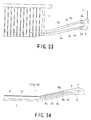
- Fig. 33 shows an example of the configuration thereof.
- a lower coil 2b and an upper coil 2a are inserted through grooves formed in a central portion along a radial direction of a stator core 1 formed in a cylindrical shape.
- hollow-core flat type copper wire is used alone or solid-core flat type copper wire is used as elemental wire in combination with flat wire to form conductors 3a and 3b having a rectangular sectional shape and covered with insulating layers 4a and 4b, respectively.
- the upper coil 2a and the lower coil 2b are structured such that clips 5a and 5b are brazed to ends of the conductors 3a and 3b and connected with each other through a hollow connecting conductor 6 to thereby directly cool the conductors 3a and 3b with cooling water, for example, deionized water supplied from an insulating connecting pipe 7.
- internal electrodes 8a, 8b, and 8g are provided in insulating layers 9, 9a, 9b, and 9c to suppress generation of electric field on the coil surface as shown in Figs. 33 and 34 .
- the three-layer internal electrodes 8a, 8b, and 8g are described by way of example, but internal electrodes of two layers or four or more layers may be adopted.
- the innermost internal electrode 8a is referred to as the first internal electrode 8a
- the intermediate internal electrode 8b is referred to as the second internal electrode 8b
- the outermost internal electrode 8g is referred to as the third internal electrode 8g, which are arranged in the order from the conductors 3a and 3b of the coil 2 toward the outer edge of the coil.
- the conductors 3 of the coils 2 (a pair of the upper coil 2a and the lower coil 2b) are covered with the insulating layers 9, 9a to 9c, the insulating layers 9, 9a to 9c are provided with the three electrodes, that is, the first internal electrode 8a, the second internal electrode 8b, and the third internal electrode 8g, the third internal electrode 8g is connected with a low-resistance layer 10 as the outermost layer of a linear portion of the coils 2 (2a and 2b), and the first internal electrode 8a and the second internal electrode 8b divide a capacitance of the insulating layers 9a, 9b, and 9c to suppress generation of electric field at the outer surface of the insulating layer in a coil end portion.
- ends of the coil end portion are provided with the clips 5 (5a and 5b) including the insulating connecting pipe 7 for directly cooling the conductors 3 (3a and 3b) with cooling water.
- the invention related to the residual life predicting technique is disclosed in, for example, Japanese Unexamined Patent Application Publication No. 9-93873 .
- the disclosed technique cuts a brazed portion between the clip at the end of the stator coil and the conductor for the sampling purpose and then examined to determine when cooling water starts leaking and predict a residual life based on data on a decreasing rate of a breakdown voltage which would drop after the leakage.
- an object of the present invention is to provide a coil residual life predicting method and apparatus capable of estimating a breakdown voltage of an insulating layer and predicting a residual life based on the estimated breakdown voltage without damaging the layer and removing a coil involving leakage from a conductor to an insulating layer.
- a coil residual life predicting method includes: a first step of checking whether or not cooling water from a conductor leaks to an insulating layer, and executing measurement necessary for estimating a breakdown voltage of a coil if the conductor cooling water leaks to the insulating layer to estimate a breakdown voltage of a coil; a second step of determining a temperature of the coil and an applied voltage based on future operating conditions of the coil to determine a decreasing rate of the breakdown voltage of the coil based on at least one of the temperature of the coil and the applied voltage; and a third step of extrapolating data obtained in the first step and the second step to determine a period necessary for the breakdown voltage to drop down to a voltage necessary for operating the coil.
- a coil residual life predicting method includes: a first step of checking whether or not cooling water from a conductor leaks to an insulating layer, and executing measurement necessary for estimating a breakdown voltage of a coil plural times with time if the conductor cooling water leaks to the insulating layer to estimate a breakdown voltage of a coil, and estimating a breakdown voltage of a coil each time the measurement is executed; a second step of drawing and extrapolating a curve representing a change of the breakdown voltage with time to predict a future decreasing tendency of the breakdown voltage; and a third step of determining a period necessary for the breakdown voltage to drop down to a voltage necessary for operating the coil based on the curve representing the change with time.
- the first step of estimating the breakdown voltage of the coil may include applying an alternative voltage to a conductor of the coil, measuring an internal electrode potential at an outer surface of an insulating layer on an internal electrode, and calculating a breakdown voltage corresponding to the measured internal electrode potential based on a previously created breakdown voltage-internal electrode potential characteristic diagram.
- the first step of estimating the breakdown voltage of the coil may include applying an alternative voltage to a conductor of the coil, measuring an internal electrode potential at an outer surface of an insulating layer on an internal electrode, determining a ratio between the measured internal electrode potential and an initial value of the internal electrode potential or an internal electrode potential of the coil determined not to suffer leakage of the conductor cooling water into the insulating layer, and calculating a breakdown voltage corresponding to the determined ratio based on a previously created breakdown voltage-ratio-between-internal electrode-potential-and-initial-value characteristic diagram.
- the first step of estimating the breakdown voltage of the coil may include applying an alternative voltage to a conductor of the coil, measuring an internal electrode potential at an outer surface of an insulating layer on an internal electrode, determining a ratio between adjacent internal electrode potentials, and calculating a breakdown voltage corresponding to the determined ratio based on a previously created breakdown voltage-ratio-between-adjacent-internal electrode-potentials characteristic diagram.
- the first step of estimating the breakdown voltage of the coil may include attaching a measurement electrode to an outer surface of an insulating layer including the internal electrode and an outer surface of an insulating layer in a portion apart from the internal electrode, measuring dielectric characteristics between the measurement electrode and the internal electrode and between the measurement electrode and a conductor in the portion apart from the internal electrode, and calculating a breakdown voltage corresponding to the determined dielectric characteristics based on a previously created breakdown voltage-dielectric characteristic diagram.
- the first step of estimating the breakdown voltage of the coil may include attaching a measurement electrode to an outer surface of an insulating layer including the internal electrode and an outer surface of an insulating layer in a portion apart from the internal electrode, measuring dielectric characteristics between the measurement electrode and the internal electrode and between the measurement electrode and a conductor in the portion apart from the internal electrode, determining a ratio of dielectric characteristics at two frequencies, and calculating a breakdown voltage corresponding to the determined ratio based on a previously created diagram showing a breakdown voltage-dielectric characteristic change rate with frequency.
- the first step of estimating the breakdown voltage of the coil may include determining an appropriate breakdown voltage value if two breakdown voltage values are obtained for one internal electrode potential upon calculating the breakdown voltage based on one of a breakdown voltage-internal electrode potential characteristic diagram, a breakdown voltage-ratio-between-internal electrode-potential-and-initial-value characteristic diagram, and a breakdown voltage-ratio-between-adjacent-internal electrode-potentials characteristic diagram, in combination with a breakdown voltage-dielectric characteristic diagram.
- the first step of estimating the breakdown voltage of the coil may include determining an appropriate breakdown voltage value if two breakdown voltage values are obtained for one internal electrode potential upon calculating the breakdown voltage based on one of a breakdown voltage-internal electrode potential characteristic diagram, a breakdown voltage-ratio-between-internal electrode-potential-and-initial-value characteristic diagram, and a breakdown voltage-ratio-between-adjacent-internal electrode-potentials characteristic diagram, based on a change of a previously measured potential.
- the second step of estimating a decreasing rate of the breakdown voltage of the coil may include: supplying and circulating water that is kept at a constant pressure and is set at two or more temperatures through a plurality of conductors of a plurality of coils that have a hole of a predetermined size in hollow elemental wire near a clip and are not subjected to leakage of water, or of coils determined to suffer leakage of the conductor cooling water into the insulating layer during operation; executing a dielectric test at a plurality of positions different in the degree at which the cooling water infiltrates, at the two or more temperatures; creating a breakdown voltage-hot water circulation period diagram based on the determined breakdown voltage and hot water circulation period and determining a decreasing rate of the breakdown voltage based on the breakdown voltage-hot water circulation period diagram; creating an Arrhenius plot representative of a relation with the temperature of circulating water based on the determined decreasing rate of the breakdown voltage; and calculating a decreasing rate of the breakdown voltage corresponding to a predetermined temperature of the circulating water
- the second step of estimating a decreasing rate of the breakdown voltage of the coil may include: a step A of supplying and circulating water that is kept at a constant pressure and is set at one temperature through a plurality of conductors of a plurality of coils that have a hole of a predetermined size in hollow elemental wire near a clip and are not subjected to leakage of water, or of coils determined to suffer leakage of the conductor cooling water into the insulating layer during operation, executing a dielectric test at a plurality of hot water circulation points different in the degree at which the cooling water infiltrates and then disassembling the coil to sample the insulating layer and measure a content Ga of a chemically specific group S in a resin of the insulating layer which changes due to hydrolysis, and determining a change rate Ka of the breakdown voltage relative to the content Ga, and a change speed Ua of the content Ga with respect to a hot water circulation period; a step B of bringing a test piece of an insulating layer cut out from
- the second step of estimating a decreasing rate of the breakdown voltage of the coil may include: a step (step A) of supplying and circulating water that is kept at a constant pressure and is set at one temperature through a plurality of conductors of a plurality of coils that have a hole of a predetermined size in hollow elemental wire near a clip and are not subjected to leakage of water, or of coils determined to suffer leakage of the conductor cooling water into the insulating layer during operation, executing a dielectric test at a plurality of hot water circulation points different in the degree at which the cooling water infiltrates and then disassembling the coil to sample the insulating layer and measure a content Ga of a chemically specific group S in a resin of the insulating layer which changes due to hydrolysis and a content Ga 0 of the specific group S in a normal insulating layer (initial value of a content of the specific group S) to determine a change amount ⁇ Ga (
- the second step of estimating a decreasing rate of the breakdown voltage of the coil may include: supplying and circulating hot water that is kept at a constant pressure and is set at a predetermined temperature through a plurality of conductors of a plurality of coils that have a hole of a predetermined size in hollow elemental wire near a clip and are not subjected to leakage of water, or of coils determined to suffer leakage of the conductor cooling water into the insulating layer during operation under conditions that linear portions of a part of the plurality of coils are applied with a predetermined voltage and the rest is not applied with a voltage, executing a dielectric test at a plurality of points different in the degree at which the water infiltrates; creasing a breakdown voltage-hot water circulation period diagram based on the determined breakdown voltage and hot water circulation period; and determining decreasing rates of the breakdown voltage for the coils applied with the voltage and the coils not applied with the voltage during the hot water circulation based on the breakdown voltage-hot water circulation period diagram and determining an increase
- the second step of estimating a decreasing rate of the breakdown voltage of the coil may include: periodically measuring an internal electrode potential from an outer surface of an insulating layer on an internal electrode for a coil of an actually operating coil; measuring dielectric characteristics between a measurement electrode provided on the outer surface of the insulating layer of the coil in the portion apart from the internal electrode and the conductor to grasp a timing at which cooling water starts leaking into the insulating layer based on a change in measurement value; taking the coil off after the elapse of a predetermined period; and determining a difference between an estimated value of the breakdown voltage in the case where the cooling water does not leak and an actual breakdown voltage based on an operation period from the timing at which the cooling water starts leaking to the insulating layer to removal of the coil, and a decreasing rate of a breakdown voltage of the coil at the timing at which the cooling water starts leaking to the insulating layer.
- the first step of estimating the breakdown voltage of the coil may include creating a breakdown voltage-internal electrode potential characteristic diagram, a breakdown voltage-ratio-between-internal electrode-potential-and-initial-value characteristic diagram, a breakdown voltage-ratio-between-adjacent-internal electrode-potentials characteristic diagram, a breakdown voltage-adjacent-electrodes characteristic diagram, and a diagram a breakdown voltage-dielectric characteristic change rate with frequency based on an internal electrode potential measured at an outer surface of an insulating layer on an internal electrode just before a dielectric test for a plurality of coils suffering leakage of cooling water, dielectric characteristics between a measurement electrode placed on the outer surface of the insulating layer and a conductor and between the measurement electrode and the internal electrode, and a breakdown voltage measured after the measurements; and estimating a breakdown voltage based on the created diagrams at subsequent measurements.
- a coil residual life predicting apparatus includes: a non-contact surface electrometer for measuring a potential of an internal electrode provided in an insulating layer that covers a coil; and a dielectric characteristic measuring apparatus for measuring dielectric characteristics between at least one of the internal electrode and a conductor and a measurement electrode attached to an outer surface of the insulating layer of the coil to predict a residual life based on a breakdown voltage estimated based on the measured potential, wherein upon attaching the measurement electrode to the insulating layer, a probe of the non-contact surface electrometer is moved along the coil, and the measurement electrode is attached to the surface of the insulating layer at a position where a stable surface potential is detected.
- a coil residual life predicting apparatus includes: a non-contact surface electrometer for measuring a potential of an internal electrode provided in an insulating layer that covers a coil; and a dielectric characteristic measuring apparatus for measuring dielectric characteristics between at least one of the internal electrode and a conductor and a measurement electrode attached to an outer surface of the insulating layer of the coil to predict a residual life based on a breakdown voltage estimated based on the measured potential and the dielectric characteristics, wherein the dielectric characteristic measuring apparatus has a high-pressure terminal connected with at least one of an output terminal and a neutral terminal of a device to be measured and has a low-pressure terminal connected with the measurement electrode attached to the outer surface of the insulating layer of the coil.
- a coil residual life predicting apparatus includes: a non-contact surface electrometer for measuring a potential of an internal electrode provided in an insulating layer that covers a coil; and a dielectric characteristic measuring apparatus for measuring dielectric characteristics between at least one of the internal electrode and a conductor and a measurement electrode attached to an outer surface of the insulating layer of the coil to predict a residual life based on a breakdown voltage estimated based on the measured potential and the dielectric characteristics, wherein the dielectric characteristic measuring apparatus has a high-pressure terminal connected with at least one of a casing for accommodating the coil and an iron core and has a low-pressure terminal connected with the measurement electrode attached to the outer surface of the insulating layer of the coil.
- the coil residual life predicting method is implemented through a first step of checking whether or not cooling water from a conductor leaks to an insulating layer, and executing measurement necessary for estimating a breakdown voltage of a coil if the conductor cooling water leaks to the insulating layer to non-destructively estimate a breakdown voltage of a coil; a second step of non-destructively estimating a curve showing a future decrease in coil breakdown voltage; and a third step of extrapolating data obtained in the first and second steps to determine a period necessary for the breakdown voltage to drop down to a voltage necessary for operating the coil.
- the residual life of the coil can be non-destructively, simply, and readily estimated, making it possible to speedily respond to quick exchange and maintenance of a coil.
- the position of the internal electrode in the insulating layer is detected from the outer surface of the insulating layer, and the electrode is set in an appropriate position of the outer surface of the insulating layer, and also, the dielectric characteristic measuring apparatus and terminals thereof are connected to an appropriate portion, enabling a high measurement accuracy of the dielectric characteristics and highly accurate prediction of the coil residual life.
- the embodiments of the present invention will be described taking a stator coil of a large-capacity turbine generator as an example, but the present invention is not limited to the example and is applicable to any other possible direct water-cooled coil provided with an internal electrode in an insulating layer.
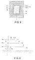
- a conductor 12 of a coil 11 including an upper coil and a lower coil is covered with insulating layers 13 (first insulating layer 13a, 13b, and 13c), a first internal electrode 14a, a second internal electrode 14b, and a third internal electrode 14g are provided in the insulating layers 13 (first insulating layer 13a, the second insulating layer 13b, and the third insulating layer 13c), and the outermost third internal electrode 14g is connected with a low-resistance layer 15 of the coil 11 while a clip 17 including an insulating connecting pipe 16 for supplying cooling water to the conductor 12 at the end of the coil 11 is provided.
- a first insulating layer 13a, a second insulating layer 13b, and a third insulating layer 13g are provided around the conductor 12 at the central position, between the first internal electrode 14a, the second internal electrode 14b, and the third internal electrode 14g in the order from an inner edge to an outer edge. If the cooling water leaks into the insulating layers, the water infiltrates from the innermost insulating layer to the outer layer. Assuming that the cooling water infiltrates halfway through the insulating layer 13a, the first insulating layer 13a is divided into a cooling water infiltration regain 18a and a dry region 18b not impregnated with the cooling water.
- the outermost third internal electrode 14g is grounded to an iron core (not shown) through the low-resistance layer 15. Further, the first internal electrode 14a and the second internal electrode 14g provided between the third internal electrode 14g and the conductor 12 are electrodes having floating potentials and having end portions shifted from each other. Their potentials are determined based on a divided voltage of a capacitance.
- an internal electrode potential measuring apparatus for measuring a potential of an internal electrode of a coil includes a potential measuring probe 19 that is moved to and fro on the outer surface of the coil 11 to determine positions of the first internal electrode 14a, the second internal electrode 14b, and the third internal electrode 14g and measuring a potential of the internal electrodes 14a and 14b, a non-contact surface electrometer 20 connected with a probe connecting terminal 20 through a lead line from the potential measuring probe 19, and a voltage measuring apparatus 22 such as an AC voltmeter or oscilloscope connected from a waveform output terminal 21 of the non-contact surface electrometer 20 through a lead line.
- the voltage measuring apparatus 22 reads an alternating voltage applied to the conductor 12 from an AC power supply 23 and a potential output from the non-contact surface electrometer 20.
- the infiltration of the cooling water is detected based on the phenomenon that the internal electrode potential increases if the conductor cooling water infiltrates into any one of the first insulating layer 13a, the second insulating layer 13b, and the third insulating layer 13g.
- the alternating voltage is applied to the coil conductor to measure a surface potential of the insulating layers 13 along the axial direction as shown in Fig. 26 and determine a position of the internal electrode to arrange measurement electrodes 24a, 24b, and 24s in appropriate positions, making it possible to measure dielectric characteristics with almost no error.
- the alternating voltage applied to the conductor 13 from the AC power supply 23 is sine wave but may be a rectangular or triangular wave.
- a frequency of the alternating voltage is preferably a low frequency, for example, 100 Hz or lower in consideration of moisture absorption accompanying the leakage of the conductor cooling water to the first insulating layer 13a, the second insulating layer 13b, and the third insulating layer 13c.
- Fig. 6 shows an equivalent circuit for measuring potentials of the first internal electrode 14a, the second internal electrode 14b, and the third internal electrode 14g if leaked water of the conductor cooling water infiltrates in the order from the first insulating layer 13a to the third insulating layer 13c.
- a capacitance defined between the conductor 12 and the first internal electrode 14a is represented by Ca
- a capacitance defined between the conductor 12 and the second internal electrode 14b is represented by Cb
- a capacitance defined between the conductor 12 and the third internal electrode 14g is represented by Cc.
- an equivalent resistor Ra that simulates a dielectric loss of the first insulating layer 13a is provided between the conductor 12 and the internal electrode 14a.
- a potential Va of the first internal electrode 14a and a potential Vb of the second internal electrode 14b are represented by the following expression:
- Va 1 / Cb + 1 / Cc / 1 / Ca + 1 / Cb + 1 / Cc x
- Vb 1 / Cc / 1 / Ca + 1 / Cb + 1 / Cc x
- a dielectric constant of the cooling water is too large (a dielectric constant of a dry insulating layer is about 4.5 in comparison with a dielectric constant of the cooling water of about 80), so the capacitance Ca of the first insulating layer 13a impregnated with the leaked conductor cooling water increases. Further, a conductivity of the leaked conductor cooling water is much lower than that of the insulating layer, so that a dielectric loss considerably increases.
- the equivalent resistor Ra is provided between the conductor 12 and the first internal electrode 14a.
- the potential Va 50.0 V based on Expression (1) if the conductor cooling water does not leak to the first insulating layer 13a.
- the capacitance Ca shows a three-fold increase, more specifically, the capacitance Ca increases to 3600 pF, and in addition, the dielectric loss increases, and the dielectric tangent (tan ⁇ ) increases to 0.2 (in normal cases, generally about 0.01 or less), the potential Va of the first internal electrode 14a is calculated (calculating expression is complicated and thus omitted) and equals 75.6 V, which value is 51% higher than that of the normal one.
- Table 1 summarizes the above values and a potential Vb of the second internal electrode 14b that is calculated based on Expression (2).
- Table 1 Coil state Potential Va (V) of first internal electrode a Potential Vb (V) of second internal electrode b Vb/Va Normal 50.0 20.0 0.4 Cooling water infiltration 75.6 30.2 0.4 V (cooling water infiltration)/V (normal) 1.51 1.51 -
- the potential of the second internal electrode 14b is also increased by 51% due to the leakage of the conductor cooling water.
- a change in potential of the internal electrode correlates with the breakdown voltage.
- the breakdown voltage would be estimated based on the potential of the internal electrode.
- Fig. 1 is a block diagram illustrating the coil residual life predicting method according to the embodiment of the present invention.
- the coil residual life predicting method of this embodiment includes a first step (step 1) of determining whether or not the cooling water from the conductor leaks to the insulating layer, and estimating a coil breakdown voltage if the conductor cooling water leaks to the insulating layer, a second step (step 2) of a decreasing rate of the coil breakdown voltage due to at least one of a coil temperature predicted from running conditions of the coil and the applied voltage, and a third step (step 3) of extrapolating data of the first and second steps to determine a period necessary for the breakdown voltage to decrease down to a level necessary for operating a coil.
- the coil residual life predicting method of this embodiment including the above steps first determines whether or not the cooling water leaks from the conductor to the insulating layer by measuring a potential of the internal electrode through a surface potential measuring probe and estimates, if the conductor cooling water leaks, the breakdown voltage of the coil damped with the leaked conductor cooling water based on a predetermined chart showing a relation between the internal electrode potential and the breakdown voltage in the first step (specific example of step 1 is described below) to plot the estimated value to a point A on Fig. 2 .
- an applied voltage is determined based on the coil temperature estimated from the future running conditions of the coil and the coil connecting position.
- the decreasing rate of the breakdown voltage under the running conditions of the coil is determined.
- a line L indicative of the decreasing rate of the breakdown voltage determined in the second step is drawn (extrapolated) so as to pass the point A of Fig. 2 to determine a period necessary for decreasing the voltage down to a voltage E 0 necessary for operating the coil, that is, a time point B at which the service life expires. Then, a period from a current time (measurement time) to the time point B is estimated as a residual life.
- the coil residual life predicting method of this embodiment estimates the breakdown voltage of the coil suffering the leakage of the conductor cooling water to calculate a service life based on one of the estimated data.
- the present invention is not limited to this example.
- the breakdown voltage of the coil suffering the leakage of the cooling water may be determined periodically as A 1 , A 2 , ..., A 6 , ..., and in the second step, a curve indicating a breakdown voltage change with time is drawn and further extrapolated, and then in the third step, the time point B on the curve at which the voltage is decreased down to the voltage E 0 necessary for operating the coil may be determined to predict a residual life of the coil.
- the coil residual life predicting method of this embodiment estimates the breakdown voltage in the first step (step 1), determines the decreasing rate of the breakdown voltage in the second step (step 2), and extrapolates data obtained in the first and second steps to predict a residual life, that is, a period necessary for the breakdown voltage to decrease down to the level necessary for operating the coil in the third step (step 3).
- a residual life that is, a period necessary for the breakdown voltage to decrease down to the level necessary for operating the coil in the third step (step 3).
- step 1 the first step (step 1) and the second step (step 2) of the coil residual life predicting method of the present invention as shown in Fig. 1 are described in this order.
- Figs. 7 and 8 are characteristic diagrams showing a breakdown voltage-internal electrode potential characteristic in the case of estimating a breakdown voltage in the first step (step 1) of the coil residual life predicting method according to the first embodiment of the present invention.
- Fig. 7 is a characteristic diagram showing a breakdown voltage-internal electrode potential characteristic in the case of providing the insulating layer with two (two-layer) internal electrodes.
- Fig. 8 is a characteristic diagram showing a breakdown voltage-internal electrode potential characteristic in the case of providing the insulating layer with three (three-layer) internal electrodes.
- an initial value of the breakdown voltage varies depending on a rated voltage of a coil or an insulating material.
- a ratio of a target breakdown voltage to an initial value is expressed as a percentage.
- step 1 the potential measuring probe 19 of Fig. 4 is moved to and fro on the outer surface of the insulating layers 13 or is brought near the measurement electrodes 24a, 24b, and 24s of Fig. 26 to measure a potential.
- the breakdown voltage is derived from the prepared breakdown voltage-internal electrode potential characteristic diagram based on ratios Va/E and Vb/E of the measured potentials Va (two-layer internal electrodes) and Vb (three-layer internal electrodes) to the applied voltage E.
- the breakdown voltage-internal electrode potential characteristic diagram is prepared based on experimental data or the like, so that the breakdown voltage can be readily determined based on the measured potentials Va and Vb.
- the potentials of the internal electrode cannot be directly measured, and instead, the potential at the outer surface of the insulating layer is measured. However, these potentials are approximate to each other. Thus, for ease of explanation, the measurement of the potential at the outer surface is referred to as “measurement of an internal electrode potential” or the potential at the outer surface is referred to as “internal electrode potential”.
- Figs. 9 and 10 are breakdown voltage-ratio between internal electrode potentials and initial values characteristic diagram in the first step (step 1) of the coil residual life predicting method according to the second embodiment of the present invention.
- the breakdown voltage can be readily estimated.
- Fig. 9 is a breakdown voltage-ratio between internal electrode potentials and initial values characteristic diagram showing a relation between the breakdown voltage and a ratio between a potential V14a of an internal electrode "a" of a coil including two (two-layer) internal electrodes and initial values.
- Fig. 10 is a breakdown voltage-ratio between internal electrode potentials and initial values characteristic diagram showing a relation between the breakdown voltage and a ratio between potentials Va and Vb of internal electrodes 14a and 14b of a coil including three (three-layer) internal electrodes and initial values (referred to as Va 0 and Vb 0 ).
- the initial values Va 0 and Vb 0 are determined by measuring during manufacturing of the coil or at the initial stage of the coil operation, or by measuring potentials of many coils at the time of measuring the potentials Va and Vb and selecting values determined as normal values in the measurement value distribution.
- an average value of all measurement data may be used as the simplest method.
- Fig. 11 is a breakdown voltage-ratio between internal electrode potentials and initial values characteristic diagram in the first step (step 1) of a coil residual life predicting method according to a third embodiment of the present invention.
- a ratio between potentials of two adjacent electrodes in the layer structure of a coil including three or more (three-layer) internal electrodes, that is, two or more (two-layer) internal electrodes of a floating potential (in the case of two internal electrodes of a floating potential, Vb/Va) is constant (see Table 1) if the conductor cooling water leaks and infiltrates in between the two internal electrodes, and otherwise, the ratio increases.
- a relation between the ratio between the two internal electrode potentials and the breakdown voltage is previously determined by experiment, and the breakdown voltage is estimated based on the determined ratio between the potentials of the two adjacent internal electrodes of the coil.
- the breakdown voltage can be readily estimated.
- Fig. 12 is a breakdown voltage-ratio between internal electrode potentials and initial values characteristic diagram in the first step (step 1) of a coil residual life predicting method according to a fourth embodiment of the present invention.
- the dielectric characteristic includes a capacitance, a dielectric loss, a dielectric loss angle, a dielectric tangent (tan ⁇ ), and moment. These can be all utilized even if the leaked water infiltrates into the insulating layer.
- the thickness of the insulating layer is non-uniform.
- a fixing member for fixing the coil is provided at the coil end portion. In some cases, the measurement electrode size varies depending on the coil.
- Fig. 12 is a breakdown voltage-ratio between internal electrode potentials and initial values characteristic diagram for a coil including three (three-layer) internal electrodes.
- Fig. 12 is a chart of a dielectric tangent tan ⁇ 0 of the conductor after the cooling water leaks to the insulating layer from the conductor, a dielectric tangent tan ⁇ a of the first internal electrode "a", and a dielectric tangent tan ⁇ b of the second internal electrode "b”.
- the leakage of the conductor cooling water to the insulating layer can be readily and surely grasped.
- a fifth embodiment as means for checking leakage of the conductor cooling water to the insulating layer in the first step (step 1) is described.
- This embodiment is based on the phenomenon that if the conductor cooling water leaks to the insulating layer, the dielectric characteristic has higher dependence on a frequency in accordance with a leakage amount of the conductor cooling water.
- Fig. 13 shows frequency characteristic of a capacitance between three (three-layer) internal electrodes and measurement electrodes
- Fig. 14 shows frequency characteristics as the product of the capacitance by the dielectric tangent.
- the solid line represents characteristics of a dry insulating layer
- the dotted line represents characteristics of an insulating layer about 3% of which is damped with the conductor cooling water
- the dashed line represents characteristics of an insulating layer about 70% of which is damped with the conductor cooling water.
- dielectric characteristics of 1 kHz/dielectric characteristics of 10 kHz a relation between dielectric characteristics of 1 kHz/dielectric characteristics of 10 kHz and a percentage of conductor cooling water that leaks to the insulating layer is shown in a chart of the breakdown voltage-change in dielectric characteristics with frequency.
- Fig. 16 is a chart of the breakdown voltage-change in dielectric characteristics with frequency of a coil including two (two-layer) internal electrodes.
- the solid line represents a ratio between measurement values at 1 kHz and 10 kHz as the product of the dielectric tangent by a capacitance between the conductor and the measurement electrode attached to the insulating layer surface on the conductor near the clip of the coil having no internal electrode.
- the broken line represents a ratio between measurement values at 1 kHz and 10 kHz as the product of the dielectric tangent by a capacitance between the conductor and the measurement electrode attached to the insulating layer surface on the internal electrode.
- the breakdown voltage can be readily and simply estimated by measuring and comparing dielectric characteristics with at least two frequencies.
- Figs. 17 and 18 are characteristic diagrams showing a breakdown voltage-internal electrode potential characteristic in the first step (step 1) of a coil residual life predicting method according to a sixth embodiment of the present invention.
- Fig. 17 is a characteristic diagram showing a breakdown voltage-internal electrode potential characteristic, which demonstrates a relation between the breakdown voltage and the potential Va of the internal electrode "a" of the coil including three (three-layer) internal electrodes as shown in Fig. 8 .
- the dielectric tangent tan ⁇ a of the insulating layer on the internal electrode "a" is 1.8% (B' region).
- This tangent tan ⁇ a of 1.8% is a pre-stage (B') just before the abrupt increase, in which the breakdown voltage is supposed to be about 50% or more.
- the breakdown voltage is estimated as 59% (point B of Fig. 17 ) when the potential Va is 83%.
- the breakdown voltage never drops down to 17%, and is estimated as 59%.
- the determination is executed in combination with the breakdown voltage-dielectric characteristic diagram, so that an appropriate breakdown voltage value can be obtained.
- Fig. 19 is a breakdown voltage-internal electrode potential characteristic diagram in the first step (step 1) of a coil residual life predicting method according to a seventh embodiment of the present invention.
- the breakdown voltage-internal electrode potential characteristic diagram is referenced in combination with the breakdown voltage-dielectric characteristic diagram to select an appropriate value from the obtained two breakdown voltage values based on the change in breakdown voltage with time.
- Fig. 19 shows an example of the above procedure.
- the breakdown voltage is estimated as 71% (point A) based on the measurement result of the dielectric tangent tan ⁇ .
- the change in measured potential with time is taken into consideration with respect to the two breakdown voltage values calculated from the breakdown voltage-internal electrode potential characteristic diagram, and thus, an appropriate breakdown voltage can be selected.
- step 2 a method of determining a decreasing rate of the breakdown voltage in the second step (step 2) of the coil residual life predicting method according to the first embodiment.
- This embodiment uses a coil prepared by removing a part of the insulating layer covering the clips of 6 coils not subjected to leakage of the conductor cooling water to the insulating layer, forming a 0.3-mm ⁇ hole in one hollow elemental wire and ensuring a clearance around the hole not to block the leakage of the water from the hollow wire and reinsulating the coils.
- ion-exchanged water the temperature of which is set to 95°C, 80°C, and 70°C under the control is circulated through every two coils.
- the internal electrode potential is periodically measured to estimate the breakdown voltage based on how much the cooling water leaks to the insulating layer and the breakdown voltage-internal electrode potential characteristic diagram. Further, right and left coil end portions of the two coils through which the ion-exchanged water is circulated at each temperature (95°C, 80°C, and 70°C) are independently subjected to breakdown at different timings.
- a chart (called “Arrhenius plot") is created as shown in Fig. 21 based on a gradient (slope) of Fig. 20 .
- the vertical axis represents the logarithm of the decreasing rate of the breakdown voltage
- the horizontal axis represents the reciprocal of the absolute temperature.
- the defect or corrosion of the brazed portion variously changes.
- the test is executed with the size or number of holes formed in the above hollow elemental wire, influences on the speed at which the leaked water infiltrates into the insulating layer, and the decreasing rate of the breakdown voltage can be grasped based on a difference in amount of the leaked water that infiltrates in the insulating layer.
- the hole is artificially formed in the hollow elemental wire to guide the water to the outside.
- the coil suffering the water leakage during the operation of the generator may be taken off from the generator and used as a sample of the hot water circulation test. In this case, although the variation is large, there is an advantage in that the test can be executed under conditions similar to the actual conditions.
- Figs. 22 , 23, and 24 are charts illustrating a method of determining the decreasing rate as second and third embodiments of the breakdown voltage in the second step (step 2) of the coil residual life predicting method according to the first embodiment.
- This embodiment determines the decreasing rate of the breakdown voltage at a given temperature through the coil hot water circulation test at one temperature and a hygrothermal aging test using a test piece of the insulating layer at plural temperatures.
- the hydrothermal aging degree correlates with the ester group decreasing degree or the increasing degree of the organic acid or the hydroxyl group.
- This embodiment utilized such phenomenon, and tests the dependency on the temperature of the hydrothermal aging rate using the sample (test piece) of the insulating layer to determine the decreasing rate of the breakdown voltage at a given temperature based on the test result and the degradation test result at one temperature for the actual coil.
- the determined decreasing rate of the breakdown voltage (-d (BDV)/dt, BDV: breakdown voltage, t: time) is modified as follows.
- the first term of the right side of Expression (3) is calculated using the actual coil hot water circulation test or the actual operating coil, and the second term is calculated using the hygrothermal aging test of the test piece of the insulating layer.
- the test similar to the hot water circulation test in the second step (step 2) of the coil residual life predicting method of the first embodiment of the invention is executed at only one temperature in the coil hot water circulation test at one temperature.
- the test temperature may be set based on the test period but is preferably set high since the higher temperature enables a shorter test period.
- the ion-exchanged water of 95°C is circulated through several conductors, and the coil dielectric test is executed after 2 and 5 months to determine the breakdown voltage.
- the breakdown voltage-hot water circulation time chart (plot at 95°C of Fig. 20 ) is created based on the test result, and the decreasing rate of the breakdown voltage at one temperature, 95°C, of the coil is determined as apparent from the slope of the diagram.
- the insulating layer is disassembled and sampled to measure the contents Ga of the ester group as the specific group S in the insulating layer using infrared absorption spectrum.
- the insulating layer not damped with the leaked conductor cooling water is cut into a test piece of a rectangular shape measuring, for example, 40 mm x 50 mm and immersed in the ion-exchanged water where the conductor cooling water temperature is set to 95°C, 80°C, and 70°C, for example, under the control and then taken out at predetermined intervals to measure the ester group contents Gb in the insulating layer using the infrared absorption spectrum.
- the change of the ester group contents Ga and Gb from the initial ester group contents Ga 0 and Gb 0 (non-degradation state) rather than the absolute values is important.
- differences therebetween ⁇ Ga and ⁇ Gb ( ⁇ G
- ) may be used.
- the differences ⁇ Ga and ⁇ Gb are used instead of the ester group contents ⁇ Ga and ⁇ Gb.
- the axes of graphs of Fig. 22 and 23 may be shifted by Ga 0 and Gb 0 .
- the gradient of the graph is not changed and the final result is the same.
- Fig. 22 shows a relation between the degradation period and the thus-obtained differences ⁇ Ga and ⁇ Gb from the initial values of the ester group contents.
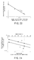
- Fig. 23 shows a relation between the coil breakdown voltage and the difference ⁇ Ga from the initial value of the ester group contents Ga in the insulating layer of the coil.
- the gradient (slope) of the regression line of the plot in the chart of Fig. 23 represents the ester group content dependency Ka of the coil breakdown voltage and corresponds to the first term of the right side of Expression (3).
- the relation between the degradation temperature and the change rate (Ua for the coil and Ub for the test piece) of the ester group contents calculated from the gradient (slope) of the chart of Fig. 33 is Arrhenius-plotted.
- Fig. 24 shows this pot.
- the regression line X is drawn to pass points where three temperatures (95°C, 80°C, and 70°C) are blotted for the test piece of the insulating layer, and the estimated line representing the temperature dependency of the ester coil content change rate of the actual coil is drawing in parallel to the regression line X so as to pass the points where the change rate of the ester content with time of the actual coil is plotted.
- the change rate Uc with time of the ester contents in the coil insulating layer at a given temperature is calculated from the estimated line Y. For example, if the coil conductor temperature during the operation of the generator is 70°C, as apparent from Fig. 24 , the change rate Uc with time of the ester contents is (estimated as) 0.08/year.
- the change rate Uc with time of the ester contents at the predetermined temperature corresponds to the second term of the right side of Expression (3).
- the product of the thus-determined ester content dependency Ka of the coil breakdown voltage by the change rate Uc with time of the ester contents at the coil operating temperature is the decreasing rate of the breakdown voltage at the coil operating temperature.
- the ester content is used as the degradation amount.
- the present invention is not limited thereto, and an increase in contents of the organic acid may be analyzed using any chemical analyzer and used in place of the ester group of Expression (3).
- the other groups change contents thereof more sensitively due to the hydrolysis, the groups may be analyzed and used.
- the test pieces cut out from the normal coil is immersed in the ion-exchanged water set to 95°C, 80°C, and 70°C under the control. In this case, the entire surface of the test piece is brought into contact with the water.
- the water infiltrates only from the conductor alone, so the degradation may proceed more slowly than the test piece. Accordingly, in order that the degradation on the test piece due to the hot water is made closer to the actual one, five surfaces out of six surfaces are sealed with a metal plate or a moisture-resistant epoxy resin or the like, and the remaining one surface is brought into contact with the hot water.
- the test piece is pressed against an opening of a container filled with the water and only one surface of the test piece contacts the hot water. If the hydrothermal aging test is carried out in this way, the degradation condition can be similar to those of the actual coil.
- the large-scale test using the coil is limited to one temperature.
- the test piece is used to measure and analyze contents of a chemically specific group susceptible to a change due to the hydrothermal aging in the laboratory, so that the degreasing rate of the breakdown voltage can be determined in a short time with a small-scale test as compared with the method of determining the decreasing rate of the breakdown voltage only through the hot-water circulation test as described in the first embodiment.
- step 2 a fourth embodiment of the method of determining the decreasing rate of the breakdown voltage in the second step (step 2) of the coil residual life predicting method according to the first embodiment of the present invention is described.
- step 2 In the case of determining the decreasing rate of the breakdown voltage, in the test using the coil of the first and second embodiments in the second step (step 2), a high voltage is not applied during the circulation test using the ion-exchanged water.
- the insulting layer is applied with a voltage, a force (Maxwellian stress) that a substance of a high dielectric constant infiltrates acts in the insulating layer with a high electric field, and the ion-exchanged water infiltrates more quickly than the insulating layer with no electric field.
- This embodiment considers this drawback.
- a degradation test was executed for both of the case of applying the high voltage between the conductor and the semiconductor layer at the surface of the coil linear portion and the case of applying no voltage at the time of circulating the ion-exchanged water controlled to the predetermined temperature through the coil conductor, the test results of the two cases were compared, and the influence on the decreasing rate of the breakdown voltage due to the voltage application other than the temperature of the ion-exchanged water was grasped.
- step 2 The test using the coil of one of the first to third embodiments in the second step (step 2) is first implemented. As a result of the test, a decreasing rate DRBDV (voltage non-application) of the breakdown voltage due to the water leakage is obtained.
- Plural sample coils completely the same as those used in the above test are used to circulate the ion-exchanged water controlled to the predetermined temperature through the coil conductor while being kept at a constant pressure concurrently or not concurrently with the above test. At this time, the conductors of the coils are grounded, and a predetermined voltage is applied to a low-resistance layer of the coil linear portion.
- the dielectric test is executed at plural points different in the degree at which the leaked water infiltrates to thereby determine the breakdown voltage and create the breakdown voltage-hot water circulating period chart. Based on the gradient thereof, the decreasing rate DRBDV (voltage application) of the breakdown voltage due to the leakage under the voltage application is obtained. An acceleration factor due to the voltage application is derived from DRBDV (voltage application)/DRBDV (voltage non-application).
- the estimated line L representative of a further decreasing rate of the breakdown voltage may be drawn using the rate DRBDV (voltage application) for the coil that would be largely influenced by the voltage.
- the applied voltage is generally a value between the rated voltage (interline voltage) and rated voltage/ ⁇ 3 (ground potential) but may be other voltage in consideration of the acceleration degree of the degradation due to the hot water temperature.
- the test is executed using plural application voltages, the acceleration factor of the degradation due to the voltage application can be more clearly defined, and the degreasing rate of the breakdown voltage can be more accurately defined for coils applied with different levels of voltage.
- the voltage is applied to the coil, so the decreasing rate of the breakdown voltage can be determined under the conditions closer to the actual operating conditions.
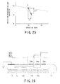
- Fig. 25 is a coil breakdown voltage-operating period chart for illustrating a method of determining a decreasing rate of the breakdown voltage as a fourth embodiment in the second step (step 2) of the coil residual life predicting method according to the first embodiment of the present invention.
- the decreasing rate of the breakdown voltage is determined based on the experimental data measured in the laboratory, but in this embodiment, the decreasing rate of the breakdown voltage is determined during the maintenance of the actually operating coil.
- the internal electrode potential of the actually operating coil is periodically measured, or the measurement electrode is attached to the outer surface of the insulating layer on the clip side rather than the range of the internal electrode, dielectric characteristics between the conductor and the measurement electrode are measured, a timing (in Fig. 25 , S) at which the leaked conductor cooling water starts infiltrating into the insulating layer is grasped based on the change in measurement value, and after the elapse of a predetermined period of, for example, 2 years (in Fig. 25 , ⁇ t), the coil is taken off to determine the breakdown voltage. Then, the decreasing rate ⁇ V/At (in Fig.
- the coil breakdown voltage is estimated based on the operation period ⁇ t from the timing S at which the leaked conductor cooling water starts infiltrating into the insulating layer to the removal of the coil (for example, 2 years) and a difference ⁇ t between the estimated value (for example, in Fig. 25 , 88%) of the breakdown voltage in the case where no conductor cooling water leaks at the time of removing the coil and the current breakdown voltage (for example 57%).
- the breakdown voltage is determined.
- the breakdown voltage-internal electrode potential characteristic diagram, the breakdown voltage-ratio between internal electrode potentials and initial values characteristic diagram, the breakdown voltage-ratio between adjacent internal electrode potentials and initial values characteristic diagram, the breakdown voltage-dielectric characteristic diagram, and the breakdown voltage-change in dielectric characteristics with frequency diagram can be created.
- Fig. 26 is a conceptual view showing a coil residual life predicting apparatus of the present invention where a measurement electrode is attached to the outer surface of an insulating layer of a coil for measuring the dielectric characteristics of the insulating layer.
- the conductor 12 and the clip 17 are covered with the insulating layers 13 (first insulating layer 13a, the second insulating layer 13b, and the third insulating layer 13c) which include the first internal electrode 14a, the second internal electrode 14b, and the third internal electrode 14g.
- the measurement electrodes 24a, 24b, and 24s are attached to the outer surface of the insulating layer, and a voltage is applied between the first internal electrode 14a, the second internal electrode 14b, and the conductor 12 to measure the dielectric characteristics.
- the surface potential measurement probe (not shown) is first moved to and fro on the outer surface of the insulating surface to measure the surface potential as shown in Fig. 26 and then, the measurement electrodes 24a, 24b, and 24s are attached in positions where the surface potential is stabilized.
- the measurement electrodes 24a, 24b, and 24s are attached to the outer surface of the insulating layer in this way, there is no displacement among the measurement electrodes 24a, 24b, and 24s to thereby suppress the measurement error.
- the measurement of a capacitance between the measurement electrodes attached to the outer surface of the insulating layer and the internal electrode needs ingenious method and idea because the measurement electrodes cannot be directly connected with the internal electrode.
- Fig. 27 is a conceptual view showing the connection between the dielectric characteristic measuring apparatus and the coil used for measuring the dielectric characteristic of the insulating layer at the coil end portion of the turbine generator, for example.
- winding 28 parallelly or serially connected with a number of coils is illustrated in a rectangular shape on a phase basis.
- each coil 25 25a and 25b
- the measurement electrode 24 (24a, 24b, and 24s) is attached to a given position of the coil end portion, and one end of a coaxial cable 30 is connected with a low-pressure terminal 29 of a dielectric characteristic measuring apparatus 27 and the other end thereof is connected with the measurement electrode 24 (24a, 24b, and 24s).
- one end of a coaxial cable 32 is connected with a high-pressure terminal 31 of the dielectric characteristic measuring apparatus 27 and the other end thereof is connected with at least one of an output terminal 33 of a generator and a neutral terminal 34.
- the ground terminal or guard terminal 35 of the dielectric characteristic measuring apparatus 27 is not grounded.
- a capacitance characteristic (capacitance, dielectric loss, dielectric loss angle, dielectric tangent, and moment) is measured. Then, the internal electrode of a floating potential and the measurement electrode have substantially the same potential due to the large capacitance between the internal electrode and the conductor, so that the voltage generated by the dielectric characteristic measuring apparatus 27 is all applied between the internal electrode and the measurement electrode 24 (24a, 24b, and 24s) to thereby measure the dielectric characteristic with high accuracy.
- the high-pressure terminal 31 of the dielectric characteristic measuring apparatus 27 is connected with the output terminal 33 and the neutral terminal 34, but the present invention is not limited thereto.
- the high-pressure terminal 31 of the dielectric characteristic measuring apparatus 27 may be connected with a casing 36 of the generator that accommodates the coil.
- the capacitance characteristic (capacitance, dielectric loss, dielectric loss angle, dielectric tangent, and moment) is measured.
- the internal electrode of a floating potential has substantially the same potential as the ground potential, that is, as the casing 36 potential due to the large capacitance between the outermost internal electrode 14g (not shown) of the ground potential and the internal electrode.
- the voltage generated by the dielectric characteristic measuring apparatus 27 is substantially all applied between the internal electrode and the measurement electrode 24 (24a, 24b, and 24s) to thereby measure the dielectric characteristic with high accuracy.
- connection position of the coaxial cable may take any position instead of the casing 36 of the generator as long as the potential at the position is equal to the potential of the iron core 26 accommodated in the casing 36.
- the cable 32 may be directly connected with a part of the iron core 26.
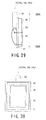
- the measurement electrode 24 (24a, 24b, and 24s) if an flexible member 38 of high insulating property such as soft rubber or sponge is attached to an insulating plate 37 as shown in Figs. 29 and 30 , and an electrode portion 39 and a guard electrode 40 are arranged thereon, or an insulating sheet 41 is inserted between the electrode portion 39 and the guard electrode 40 and core wire of the coaxial cable 30 and a sealing portion are connected with the electrode portion 39 and the guard electrode 40 as shown in Figs. 31 and 32 , the electrode portion 39 and the guard electrode 40 can be brought into close contact with the coil surface, and the guard electrode 40 suppresses the disturbance of the electric field around the electrode portion 39 that causes an error to thereby realize high-accuracy measurement.
- an insulating property such as soft rubber or sponge
- the present invention it is possible to provide a coil residual life predicting method and apparatus capable of estimating a breakdown voltage of an insulating layer and predicting a residual life based on the estimated breakdown voltage for the coil suffering the leakage of the cooling water from the conductor into the insulating layer, without removing the coil and damaging any component.
- the residual life of the coil can be easily and simply predicted without damaging any component, making it possible to speedily respond to quick exchange and maintenance of a coil.
- the high-accuracy dielectric characteristics can be measured, and the coil residual life can be more accurately predicted. Consequently, the present invention is applicable to other industrial fields than the art concerned.
Landscapes
- Engineering & Computer Science (AREA)
- Power Engineering (AREA)
- Microelectronics & Electronic Packaging (AREA)
- Manufacturing & Machinery (AREA)
- Testing Of Short-Circuits, Discontinuities, Leakage, Or Incorrect Line Connections (AREA)
- Testing Relating To Insulation (AREA)
Applications Claiming Priority (3)
| Application Number | Priority Date | Filing Date | Title |
|---|---|---|---|
| JP2003365317 | 2003-10-24 | ||
| JP2003423594A JP4497916B2 (ja) | 2003-10-24 | 2003-12-19 | コイルの余寿命推定方法およびコイルの余寿命推定装置 |
| EP04793169.6A EP1703293B1 (fr) | 2003-10-24 | 2004-10-22 | Procede et dispositif pour estimer la duree de vie restante d'une bobine |
Related Parent Applications (2)
| Application Number | Title | Priority Date | Filing Date |
|---|---|---|---|
| EP04793169.6A Division EP1703293B1 (fr) | 2003-10-24 | 2004-10-22 | Procede et dispositif pour estimer la duree de vie restante d'une bobine |
| EP04793169.6 Division | 2004-10-22 |
Publications (2)
| Publication Number | Publication Date |
|---|---|
| EP2345903A1 true EP2345903A1 (fr) | 2011-07-20 |
| EP2345903B1 EP2345903B1 (fr) | 2017-07-19 |
Family
ID=34525453
Family Applications (2)
| Application Number | Title | Priority Date | Filing Date |
|---|---|---|---|
| EP04793169.6A Expired - Lifetime EP1703293B1 (fr) | 2003-10-24 | 2004-10-22 | Procede et dispositif pour estimer la duree de vie restante d'une bobine |
| EP11162776.6A Expired - Lifetime EP2345903B1 (fr) | 2003-10-24 | 2004-10-22 | Procédé et dispositif pour estimer la durée de vie restante d'une bobine |
Family Applications Before (1)
| Application Number | Title | Priority Date | Filing Date |
|---|---|---|---|
| EP04793169.6A Expired - Lifetime EP1703293B1 (fr) | 2003-10-24 | 2004-10-22 | Procede et dispositif pour estimer la duree de vie restante d'une bobine |
Country Status (4)
| Country | Link |
|---|---|
| EP (2) | EP1703293B1 (fr) |
| JP (1) | JP4497916B2 (fr) |
| KR (1) | KR100805872B1 (fr) |
| WO (1) | WO2005040840A1 (fr) |
Families Citing this family (5)
| Publication number | Priority date | Publication date | Assignee | Title |
|---|---|---|---|---|
| JP4783069B2 (ja) * | 2005-06-23 | 2011-09-28 | 株式会社東芝 | コイルの水漏れ検出方法およびこの検出方法に適用する水漏れ検出装置 |
| US7616012B2 (en) * | 2007-05-11 | 2009-11-10 | General Electric Company | Systems, methods, and apparatus for measuring capacitance in a stator component |
| CN114355047B (zh) * | 2022-03-11 | 2022-05-24 | 华龙国际核电技术有限公司 | 一种棒位探测器线圈测试方法、装置及电子设备 |
| JP2024170793A (ja) * | 2023-05-29 | 2024-12-11 | 東芝エネルギーシステムズ株式会社 | 回転電機管理システム |
| CN117877028B (zh) * | 2024-03-13 | 2024-05-14 | 浙江大学 | 基于微观图像特征的电机绝缘寿命预测方法及系统 |
Citations (7)
| Publication number | Priority date | Publication date | Assignee | Title |
|---|---|---|---|---|
| JPH04299051A (ja) * | 1991-03-27 | 1992-10-22 | Mitsubishi Electric Corp | 回転電機 |
| FR2737015A1 (fr) * | 1995-07-14 | 1997-01-24 | Toshiba Kk | Procede d'evaluation d'une duree de vie restante d'une bobine de machine tournante |
| EP0758158A2 (fr) * | 1995-08-08 | 1997-02-12 | Kabushiki Kaisha Toshiba | Instrument de mesure à capacité électrostatique pour spires de stator de machines rotatives |
| JPH09331656A (ja) | 1996-03-05 | 1997-12-22 | Toshiba Corp | 測定素子を用いた点検装置、アーム装置、および円柱面周方向移動装置 |
| JPH10177053A (ja) | 1996-12-18 | 1998-06-30 | Hitachi Ltd | 回転電機の固定子コイルの劣化検知方法及び装置 |
| JP2000126293A (ja) | 1998-10-28 | 2000-05-09 | Shimadzu Corp | 針無注射器 |
| EP1503218A1 (fr) * | 2002-04-26 | 2005-02-02 | Kabushiki Kaisha Toshiba | Procede et systeme de diagnostic de deterioration de bobine |
Family Cites Families (5)
| Publication number | Priority date | Publication date | Assignee | Title |
|---|---|---|---|---|
| JPS6327771A (ja) * | 1986-07-21 | 1988-02-05 | Yaskawa Electric Mfg Co Ltd | 余寿命計 |
| JPH0997719A (ja) * | 1995-09-28 | 1997-04-08 | Makoto Yamamoto | トランス構造 |
| JP4058224B2 (ja) * | 2000-06-12 | 2008-03-05 | 株式会社フジクラ | Cvケーブル余寿命推定方法 |
| JP2001359257A (ja) * | 2000-06-13 | 2001-12-26 | Toshiba Corp | 回転電機点検装置および回転電機点検方法 |
| JP2003185690A (ja) * | 2001-12-18 | 2003-07-03 | Toshiba Corp | 電力用変圧器 |
-
2003
- 2003-12-19 JP JP2003423594A patent/JP4497916B2/ja not_active Expired - Lifetime
-
2004
- 2004-10-22 KR KR1020067007872A patent/KR100805872B1/ko not_active Expired - Lifetime
- 2004-10-22 EP EP04793169.6A patent/EP1703293B1/fr not_active Expired - Lifetime
- 2004-10-22 WO PCT/JP2004/016061 patent/WO2005040840A1/fr not_active Ceased
- 2004-10-22 EP EP11162776.6A patent/EP2345903B1/fr not_active Expired - Lifetime
Patent Citations (9)
| Publication number | Priority date | Publication date | Assignee | Title |
|---|---|---|---|---|
| JPH04299051A (ja) * | 1991-03-27 | 1992-10-22 | Mitsubishi Electric Corp | 回転電機 |
| FR2737015A1 (fr) * | 1995-07-14 | 1997-01-24 | Toshiba Kk | Procede d'evaluation d'une duree de vie restante d'une bobine de machine tournante |
| JPH0993873A (ja) | 1995-07-14 | 1997-04-04 | Toshiba Corp | 回転電機巻線の余寿命評価方法 |
| EP0758158A2 (fr) * | 1995-08-08 | 1997-02-12 | Kabushiki Kaisha Toshiba | Instrument de mesure à capacité électrostatique pour spires de stator de machines rotatives |
| JPH0951658A (ja) | 1995-08-08 | 1997-02-18 | Toshiba Corp | 回転電機用固定子巻線の静電容量測定装置 |
| JPH09331656A (ja) | 1996-03-05 | 1997-12-22 | Toshiba Corp | 測定素子を用いた点検装置、アーム装置、および円柱面周方向移動装置 |
| JPH10177053A (ja) | 1996-12-18 | 1998-06-30 | Hitachi Ltd | 回転電機の固定子コイルの劣化検知方法及び装置 |
| JP2000126293A (ja) | 1998-10-28 | 2000-05-09 | Shimadzu Corp | 針無注射器 |
| EP1503218A1 (fr) * | 2002-04-26 | 2005-02-02 | Kabushiki Kaisha Toshiba | Procede et systeme de diagnostic de deterioration de bobine |
Non-Patent Citations (1)
| Title |
|---|
| INOUE Y ET AL: "Technology for detecting wet bars in water-cooled stator windings of turbine generators", ELECTRIC MACHINES AND DRIVES CONFERENCE, 2003. IEMDC'03. IEEE INTERNAT IONAL JUNE 1-4, 2003, PISCATAWAY, NJ, USA,IEEE, vol. 2, 1 June 2003 (2003-06-01), pages 1337 - 1343, XP010643523, ISBN: 978-0-7803-7817-9 * |
Also Published As
| Publication number | Publication date |
|---|---|
| KR20060080591A (ko) | 2006-07-10 |
| EP1703293B1 (fr) | 2013-06-05 |
| EP1703293A4 (fr) | 2010-07-28 |
| EP1703293A1 (fr) | 2006-09-20 |
| KR100805872B1 (ko) | 2008-02-20 |
| EP2345903B1 (fr) | 2017-07-19 |
| JP4497916B2 (ja) | 2010-07-07 |
| JP2005148039A (ja) | 2005-06-09 |
| WO2005040840A1 (fr) | 2005-05-06 |
Similar Documents
| Publication | Publication Date | Title |
|---|---|---|
| Densley | Ageing mechanisms and diagnostics for power cables-an overview | |
| Babel et al. | Condition-based monitoring and prognostic health management of electric machine stator winding insulation | |
| CN102944777A (zh) | 电缆使用寿命检测方法 | |
| Oyegoke et al. | Application of dielectric response measurement on power cable systems | |
| CN101726514A (zh) | 基于回复电压的油浸式变压器固体绝缘含水量评估方法 | |
| CN113917293A (zh) | 基于频域时域高压干式套管绝缘老化状态评估方法及系统 | |
| EP1703293B1 (fr) | Procede et dispositif pour estimer la duree de vie restante d'une bobine | |
| Naderiallaf et al. | Assessment of edgewise insulated wire bend radius impact on dielectric properties of turn-to-turn insulation through thermal aging | |
| Koch et al. | Advanced insulation diagnostic by dielectric spectroscopy | |
| Raetzke et al. | Condition assessment of instrument transformers using Dielectric Response Analysis | |
| JP6164022B2 (ja) | 巻線機器の巻線層間絶縁診断方法 | |
| ZA200603232B (en) | Coil residual life predicting method and apparatus | |
| EP2315010A1 (fr) | Procédé de diagnostic pour équipement électrique rempli d'huile, dispositif de diagnostic pour mettre en uvre le procédé de diagnostic, et équipement électrique rempli d'huile avec dispositif de diagnostic intégré | |
| Joshi et al. | Dielectric diagnosis of EHV current transformer using frequency domain spectroscopy (FDS) & polarization and depolarization current (PDC) techniques | |
| Cherukupalli et al. | Condition assessment of distribution PILC cables from electrical, chemical, and dielectric measurements | |
| CN108593714B (zh) | 一种基于变压器内置油纸绝缘试样介电响应特性的变压器内水分测量系统 | |
| JP4973524B2 (ja) | コイル検査装置及びコイル検査方法 | |
| Rux | High-voltage dc tests for evaluating stator winding insulation: Uniform step, graded step, and ramped test methods | |
| Kilper et al. | Study on different partial discharge testing methods qualifying insulation materials for automotive applications | |
| CN116070432A (zh) | 基于改进二阶动力学模型的变压器纸绝缘聚合度评估方法 | |
| Gutten et al. | Analysis of insulating parameters of oil transformer by time and frequency methods | |
| Braun | Condition assessment of unshielded aged power and control cables by electrical techniques | |
| JP2012037483A (ja) | 部分放電発生ボイド種別の判定法 | |
| Huang et al. | Predictive monitoring of turn-to-turn insulation in single tooth coils | |
| Stahl et al. | Investigation on Insulation Failure Mechanisms of Stators used for E-Mobility |
Legal Events
| Date | Code | Title | Description |
|---|---|---|---|
| PUAI | Public reference made under article 153(3) epc to a published international application that has entered the european phase |
Free format text: ORIGINAL CODE: 0009012 |
|
| 17P | Request for examination filed |
Effective date: 20110418 |
|
| AC | Divisional application: reference to earlier application |
Ref document number: 1703293 Country of ref document: EP Kind code of ref document: P |
|
| AK | Designated contracting states |
Kind code of ref document: A1 Designated state(s): FR |
|
| 17Q | First examination report despatched |
Effective date: 20141212 |
|
| RIC1 | Information provided on ipc code assigned before grant |
Ipc: H02K 11/20 20160101ALI20161222BHEP Ipc: G01R 31/34 20060101AFI20161222BHEP Ipc: H02K 11/33 20160101ALI20161222BHEP Ipc: G01R 31/06 20060101ALI20161222BHEP Ipc: H02K 11/35 20160101ALI20161222BHEP Ipc: G01R 31/12 20060101ALI20161222BHEP |
|
| GRAP | Despatch of communication of intention to grant a patent |
Free format text: ORIGINAL CODE: EPIDOSNIGR1 |
|
| INTG | Intention to grant announced |
Effective date: 20170202 |
|
| RIN1 | Information on inventor provided before grant (corrected) |
Inventor name: SEKITO, SHINOBU Inventor name: INOUE, YOSHIYUKI Inventor name: KOYAMA, MITSUHIKO Inventor name: HASEGAWA, HIROSHI Inventor name: TONOSAKI, NOBUYUKI Inventor name: KANEIWA, HIROSHI Inventor name: OONO, SHINJI Inventor name: SHIMADA, HIDEYUKI |
|
| GRAS | Grant fee paid |
Free format text: ORIGINAL CODE: EPIDOSNIGR3 |
|
| GRAA | (expected) grant |
Free format text: ORIGINAL CODE: 0009210 |
|
| AC | Divisional application: reference to earlier application |
Ref document number: 1703293 Country of ref document: EP Kind code of ref document: P |
|
| AK | Designated contracting states |
Kind code of ref document: B1 Designated state(s): FR |
|
| REG | Reference to a national code |
Ref country code: FR Ref legal event code: PLFP Year of fee payment: 14 |
|
| PLBE | No opposition filed within time limit |
Free format text: ORIGINAL CODE: 0009261 |
|
| STAA | Information on the status of an ep patent application or granted ep patent |
Free format text: STATUS: NO OPPOSITION FILED WITHIN TIME LIMIT |
|
| 26N | No opposition filed |
Effective date: 20180420 |
|
| REG | Reference to a national code |
Ref country code: FR Ref legal event code: PLFP Year of fee payment: 15 |
|
| REG | Reference to a national code |
Ref country code: FR Ref legal event code: TQ Owner name: TOSHIBA PLANT SYSTEMS & SERVICES CORPORATION, JP Effective date: 20180903 Ref country code: FR Ref legal event code: TQ Owner name: TOSHIBA ENERGY SYSTEMS & SOLUTIONS CORPORATION, JP Effective date: 20180903 |
|
| PGFP | Annual fee paid to national office [announced via postgrant information from national office to epo] |
Ref country code: FR Payment date: 20230911 Year of fee payment: 20 |