EP2346131A2 - Arrangement de conducteurs électriques dans un dispositif isolé au gaz pour améliorer le refroidissement - Google Patents
Arrangement de conducteurs électriques dans un dispositif isolé au gaz pour améliorer le refroidissement Download PDFInfo
- Publication number
- EP2346131A2 EP2346131A2 EP10194900A EP10194900A EP2346131A2 EP 2346131 A2 EP2346131 A2 EP 2346131A2 EP 10194900 A EP10194900 A EP 10194900A EP 10194900 A EP10194900 A EP 10194900A EP 2346131 A2 EP2346131 A2 EP 2346131A2
- Authority
- EP
- European Patent Office
- Prior art keywords
- conductor
- section
- switchgear
- lateral surface
- segment
- Prior art date
- Legal status (The legal status is an assumption and is not a legal conclusion. Google has not performed a legal analysis and makes no representation as to the accuracy of the status listed.)
- Withdrawn
Links
- 239000004020 conductor Substances 0.000 title claims abstract description 351
- 238000001816 cooling Methods 0.000 title claims abstract description 19
- 238000000034 method Methods 0.000 claims abstract description 8
- 230000005484 gravity Effects 0.000 claims description 13
- 238000000465 moulding Methods 0.000 claims description 6
- 230000005855 radiation Effects 0.000 claims description 5
- 238000012856 packing Methods 0.000 claims description 3
- 238000010438 heat treatment Methods 0.000 claims 1
- 239000007789 gas Substances 0.000 description 57
- 230000000694 effects Effects 0.000 description 14
- 125000006850 spacer group Chemical group 0.000 description 13
- 238000012546 transfer Methods 0.000 description 11
- 229910018503 SF6 Inorganic materials 0.000 description 5
- SFZCNBIFKDRMGX-UHFFFAOYSA-N sulfur hexafluoride Chemical compound FS(F)(F)(F)(F)F SFZCNBIFKDRMGX-UHFFFAOYSA-N 0.000 description 5
- 229960000909 sulfur hexafluoride Drugs 0.000 description 5
- 230000002500 effect on skin Effects 0.000 description 4
- 238000009434 installation Methods 0.000 description 4
- 239000000463 material Substances 0.000 description 4
- 239000011265 semifinished product Substances 0.000 description 4
- 238000013461 design Methods 0.000 description 3
- 239000012212 insulator Substances 0.000 description 3
- 238000005452 bending Methods 0.000 description 2
- 230000012447 hatching Effects 0.000 description 2
- 241001136792 Alle Species 0.000 description 1
- RYGMFSIKBFXOCR-UHFFFAOYSA-N Copper Chemical compound [Cu] RYGMFSIKBFXOCR-UHFFFAOYSA-N 0.000 description 1
- 239000000956 alloy Substances 0.000 description 1
- 229910045601 alloy Inorganic materials 0.000 description 1
- XAGFODPZIPBFFR-UHFFFAOYSA-N aluminium Chemical compound [Al] XAGFODPZIPBFFR-UHFFFAOYSA-N 0.000 description 1
- 229910052782 aluminium Inorganic materials 0.000 description 1
- 230000015572 biosynthetic process Effects 0.000 description 1
- 239000011248 coating agent Substances 0.000 description 1
- 238000000576 coating method Methods 0.000 description 1
- 239000002131 composite material Substances 0.000 description 1
- 229910052802 copper Inorganic materials 0.000 description 1
- 239000010949 copper Substances 0.000 description 1
- 230000005684 electric field Effects 0.000 description 1
- 238000000265 homogenisation Methods 0.000 description 1
- 230000001771 impaired effect Effects 0.000 description 1
- 238000007689 inspection Methods 0.000 description 1
- 238000003754 machining Methods 0.000 description 1
- 238000004519 manufacturing process Methods 0.000 description 1
- 238000005259 measurement Methods 0.000 description 1
- 238000003801 milling Methods 0.000 description 1
- 239000000203 mixture Substances 0.000 description 1
- 238000005457 optimization Methods 0.000 description 1
- 238000005192 partition Methods 0.000 description 1
- 230000035515 penetration Effects 0.000 description 1
- 230000000704 physical effect Effects 0.000 description 1
- 238000009420 retrofitting Methods 0.000 description 1
- 239000007787 solid Substances 0.000 description 1
- 238000003860 storage Methods 0.000 description 1
Images




Classifications
-
- H—ELECTRICITY
- H02—GENERATION; CONVERSION OR DISTRIBUTION OF ELECTRIC POWER
- H02G—INSTALLATION OF ELECTRIC CABLES OR LINES, OR OF COMBINED OPTICAL AND ELECTRIC CABLES OR LINES
- H02G5/00—Installations of bus-bars
- H02G5/06—Totally-enclosed installations, e.g. in metal casings
- H02G5/063—Totally-enclosed installations, e.g. in metal casings filled with oil or gas
-
- H—ELECTRICITY
- H01—ELECTRIC ELEMENTS
- H01H—ELECTRIC SWITCHES; RELAYS; SELECTORS; EMERGENCY PROTECTIVE DEVICES
- H01H33/00—High-tension or heavy-current switches with arc-extinguishing or arc-preventing means
- H01H33/60—Switches wherein the means for extinguishing or preventing the arc do not include separate means for obtaining or increasing flow of arc-extinguishing fluid
- H01H33/66—Vacuum switches
-
- H—ELECTRICITY
- H02—GENERATION; CONVERSION OR DISTRIBUTION OF ELECTRIC POWER
- H02B—BOARDS, SUBSTATIONS OR SWITCHING ARRANGEMENTS FOR THE SUPPLY OR DISTRIBUTION OF ELECTRIC POWER
- H02B13/00—Arrangement of switchgear in which switches are enclosed in, or structurally associated with, a casing, e.g. cubicle
- H02B13/02—Arrangement of switchgear in which switches are enclosed in, or structurally associated with, a casing, e.g. cubicle with metal casing
- H02B13/035—Gas-insulated switchgear
-
- H—ELECTRICITY
- H02—GENERATION; CONVERSION OR DISTRIBUTION OF ELECTRIC POWER
- H02G—INSTALLATION OF ELECTRIC CABLES OR LINES, OR OF COMBINED OPTICAL AND ELECTRIC CABLES OR LINES
- H02G5/00—Installations of bus-bars
- H02G5/10—Cooling
Definitions
- the present invention relates to a conductor of a gas-insulated switchgear, in particular a conductor of a gas-insulated high or medium voltage switchgear.
- Such conductors are used to transmit power ratings within a switchgear, they are therefore also called nominal conductor, primary phase conductor or primary conductor.
- GIS gas-insulated circuit
- housing with an annular cross-section are often used especially for high-voltage switchgears for technical reasons.
- a cylindrical conductor with a likewise circular or annular conductor cross section is usually used per electric phase.
- the present invention aims to transfer the greater energy loss of the at least one conductor as far as possible with the existing insulating gas to the housing, even if in the switchgear section only little conductor space for the arrangement and design of a conductor is available.
- the present invention uses two physical effects.
- the first effect is that the insulating gas at a running approximately horizontally to the surface of the earth housing portion of a GIS in the operating case, i. in the case of the nominal load (continuous load) has a temperature gradient.
- the temperature is higher in the cross section through the housing seen, the upper half of the housing than in the lower half of the housing.
- the second effect is the skin effect, in which the current penetration depth is relatively low at a higher frequency alternating current of about 50 to 60 Hz in the conductor.
- the high-voltage switchgear segment according to the invention has at least one current conductor, which is arranged in an electrically insulated manner by means of an insulating gas in a metal-encapsulated housing of the switchgear section.
- the insulating gas is for example Air, O 2 , Ar, CO, CO 2 , He, N 2 , SeF 6 , NH 3 , C 2 F 6 , C 3 F 8 , CF 3 I, CF 4 or a gas mixture of at least two of these gases.
- High-voltage switchgear segment is understood to mean a section of a gas-insulated switchgear, GIS for short, extending in the direction of a nominal conductor.
- GIS gas-insulated switchgear
- As an example of such a high-voltage switchgear segment its here called a switch panel or a busbar of a substation.
- high voltage is meant in this description an operating or nominal voltage according to DIN VDE of at least 1000 volts (1 kV).
- the current conductor has at least one conductor section which extends in a longitudinal direction (Z).
- the conductor is made of a profile, depending on the embodiment of a semi-finished profile, constant cross-section.
- the profile cross section of the conductor has a height which is at least twice as large as a width of the profile cross section.
- this is a flat conductor, which has a rectangular or rectangular profile cross-section, wherein its longitudinally extending edges / corners are rounded for dielectric reasons.
- the profile or the semi-finished product may even be a standard profile, such as an extruded aluminum or copper profile.
- a lateral surface of the at least one conductor section is of its size (and orientation relative to Erdanziehungskraft) dimensioned and aligned in the housing that automatically adjusts the nominal operation of the conductor on the lateral surface a free Konvetationsströmung the insulating gas with respect to the effective direction of gravitational force opposite direction component.
- the lateral surface extends in the circumferential direction of the conductor.
- the gas movement resulting from the convection flow during operation of the switchgear on the one hand promoted slightly cooler insulating gas from a location closer to the center of the earth within the gas space enclosed by the housing in the direction of a location further away from the center of the earth, where a slightly higher temperature prevails.
- the convection flow promotes at least in the nominal operation of the gas-insulated switchgear relatively cool insulating gas from a cold gas lake pumpless and automatically in warmer zones of the high-voltage switchgear segment.
- the conductor cross-section can be selected as needed and can have a wide variety of cross-sectional shapes. Depending on the embodiment and requirements of the conductor cross-section may also be formed of different profiles or composite profile sections. In addition, the conductor may also extend in more than one direction, such as branches, supports, feedthroughs, and the like. If necessary, the conductor can also be twisted around its longitudinal axis. Such a twisted embodiment of the current conductor is thermally interesting, in particular in the case of a vertical alignment of the current conductors. This means, then, if their longitudinal axis is arranged approximately in the effective direction of gravitational force.
- the inventive high-voltage switchgear segment is not limited to applications whose current path of the conductor extends horizontally, ie in the direction of the earth's surface, but also in the vertical direction or at an angle to the effective direction of the gravitational force direction.
- a degree of freedom of the possible cross-sectional shape of the profile cross-section increases, since the free convection flows at least partially in the direction of profile running direction and thus a flow around and thus the cooling effect in the section of the lateral surface not or at least only slightly impaired.
- current leads made of semi-finished products are typically excellent for bending, for example, to make a terminal leg perpendicular to the rest of the conductor body. This is especially true in one embodiment of the conductor as a flat profile.
- an embodiment of the current conductor as a flat profile allows a very simple and subsequently cost-effective machining, such as in the form of holes or milling, or the like.
- the switchgear segment according to the invention has proven to be particularly effective in high-voltage applications.
- the insulating gas (SF6) was more than 50 kV under an absolute pressure of at least 200,000 pascals.
- a basic embodiment with a single conductor having a rectangular cross-section, a lateral surface has a first lateral surface portion and a second lateral surface portion opposite the first lateral surface portion, wherein the first and the second lateral surface portion is preferably formed by the dimensionally larger profile edges.
- the first lateral surface section and the second lateral surface section in the case of the rectangular profile cross section form the larger sides of the rectangular profile cross section.
- the lateral surface portions are partial lateral surfaces of the circumferential surface extending in the circumferential direction of the conductor. In the direction of the conductor the lateral surface sections / partial lateral surfaces are correspondingly in at least one conductor section.
- the first and / or the second lateral surface section is aligned relative to the effective direction of the gravitational force such that the insulating gas in the nominal operation of the conductor along the first and / or second lateral surface portion has a resulting flow velocity of at least 0.01m / s.
- a cooling flow has a flow direction component acting counter to the effective direction of gravity, which contributes at least 50% of the resulting flow velocity of the cooling flow.
- the heat transfer from the at least one conductor into the insulating gas can be further improved if the at least one conductor has at least partially such a surface that in the nominal operation of the conductor, the convection at the first and / or second lateral surface portion is predominantly turbulent.
- advantageous cooling values of the at least one conductor can be achieved.
- a turbulent gas flow has the advantage that the insulating gas can absorb more heat in the former, since more gas volumes can come into direct contact with the first and / or second lateral surface section than with the latter.
- suitable surface textures his here representative a coating of the conductor with a certain surface structure or a certain roughness of the conductor called.
- heat energy is understood to mean the amount of energy emitted by heat transfer from the conductor surface into the insulating gas.
- the heat transfer coefficient includes effects of radiation as well as convection.
- a theoretical measurement consisting of geometric values shows an advantageous conductor design, which optimally defines the material cost / installation space ratio.
- the conductor cross-section can not remain circular, but it will have an oblong cross-section.
- the surface (lateral surface) of the current conductor can be further increased if the height of the profile is greater than the width of the profile cross-section.
- the optimum would be a maximum height and a minimum width of the conductor so that the latter would almost only be foil-like. Since a film-like flat conductor are unsuitable for a conductor space, especially in confined spaces, there is a first optimum width to height.
- H is the height of the profile cross-section or the conductor profile
- B is the width of the gas-contacted conductor section or conductor sections (in rail packages)
- C is the profile cross section of the conductor section itself
- A is the surface of the profile cross section of the conductor profile in the conductor section touched by the insulating gas
- U is the circumference of the profile cross section
- L represents a unit longitudinal section of the conductor of one meter.
- the rectangular cross-section would in such cases be slightly changed by possibly generously dimensioned fillets on the longitudinal edges.
- generous dimensioning is understood, for example, a rounding radius of about 10mm with a width of 20mm of the profile cross-section.
- cross section of the current conductor in the light of the present description is generally understood to mean that profile cross section of the at least one current conductor which is aligned in the direction of the effective direction of gravity in the switchgear segment.
- the calculation of the quotient Z does not refer exclusively to individual conductors, but also to sub-conductors of a conductor designed as a rail package, as long as the cross-sections of each individual conductor or sub-conductor all have a similar cross-section in terms of shape and size.
- the at least one current conductor in one embodiment has a gas-contacting surface, which is enlarged in the conductor section by the fact that the current conductor is designed as a conductor package with at least two individual conductors. These individual conductors are arranged away from one another in the gas space by at least one convection channel for the insulating gas so that a convection flow of the insulating gas automatically adjusts in the convection passage in nominal operation of the conductor with a flow direction component counter to the direction of action of the gravitational force.
- the individual conductors are brought together in a connection region of the current conductor and are fastened together and electrically contacted together on an insulator in general and a sprue fitting of a post insulator or a partition insulator in particular.
- two individual conductors are at the same or different electrical potential.
- the use of electrically insulating spacers between the individual conductors is recommended, while in the former case any existing spacers may be electrically conductive.
- each individual conductor has at least one side flank extending in the direction of the height, with end regions adjoining end, so that two adjacent side flanks of two adjacent individual conductors laterally delimit the at least one convection channel located therebetween.
- an embodiment of the conductor with fittings may be necessary or useful.
- at least one end region of at least one individual conductor extends in the longitudinal direction (profile mounting direction), electrically conductive fitting, which increases the one or more individual conductors in the direction of height and / or width and which is electrically connected to the single conductor.
- An embodiment of the conductor with fittings has the advantage in the operation of the switchgear segment that the fittings contribute to the homogenization of the electric field of the at least one conductor designed as a conductor conductor in the at least one end region by the end region - seen in the conductor cross-section - locally enlarged.
- the fitting is at least partially integrated in the single conductor.
- At least two adjacent individual conductors are electrically connected to one another at the end via at least one common molding.
- a spacer arranged in the intermediate convection channel. If both individual conductors are at the same electrical potential, an electrically conductive, for example metallic, spacer can be used. However, if both individual conductors are at different electrical potentials, then the spacer (and possibly also its attachment, for example in FIG Shape of a screw) be electrically insulating. Depending on requirements, the spacer is therefore electrically and / or mechanically resilient.
- FIG. 1 is a cross-section of a basic embodiment of a high voltage switchgear segment 1 with a single conductor shown in a Longitudinal direction Y, also referred to as Y-direction extends.
- the switchgear segment 1 comprises a current conductor 2, which is arranged in the operation of the switchgear segment 1 by means of an insulating gas in a gas space 3 of a metal-encapsulated housing 4 of the switchgear section 1 electrically insulated.
- the current conductor 2 comprises a conductor section extending in the Y direction, which will be discussed in detail later.
- the current conductor 2 is made of a semifinished profile of constant cross-section.
- the profile cross-section of the conductor 2 has a height 6 which is approximately four times as large as a width 7 of the profile cross-section.
- the current conductor 2 has a lateral surface 8 with a first lateral surface section 9 and an oppositely disposed second lateral surface section 10.
- the lateral surface portions 9, 10 are dimensioned by their size and orientation relative to the gravitational force so that in the nominal operation of the conductor 2 on the lateral surface 8, that is, in particular the lateral surface portions 9, 10 automatically a free convection of the insulating gas with respect to the, effective direction of the Earth gravity '13 sets opposite directional component.
- the adjusting gas flow is shown with arrows. First, along the lateral surface portions 9, 10 flowing turbulent convection partial flows 14a, 14b show this.
- second partial flows 16a, 16b correspond to the convection partial flows 14a, 14b and inn detox along the housing wall along the housing. They give at least a portion of their absorbed thermal energy to the housing 4 and finally flow back into the cold gas lake 15.
- FIGS. 2a-2f are alternative conductor cross sections to the in FIG. 1 shown conductor profile of the conductor shown. For better clarity, the profile cross-sections are not shown hatched. The following is just for the differences to in FIG. 1 illustrated conductor 2 received. Identical or equivalent elements are provided with the same or at least similar reference numerals.
- the conductor cross-section of the current conductors 2a, 2b, 2c, 2d, 2e, 2f can be used.
- Highly angled conductor cross sections, such as that of the current conductors 2f, are recommended, for example, if the first partial flow can also flow in the profile longitudinal direction, at least in a thermally significant conductor section, since in the case of an installation position in the FIG. 1 otherwise the first partial flow could otherwise be impeded too much, which could lead to an unsatisfactory cooling effect of the current conductors 2f.
- the conductors are one-piece (2 a, 2 b, 2 c, 2 d, 2 f) or multi-part, approximately in two parts, as in the in FIG. 2e shown embodiment.
- width' in the present description does not mean the total width of the conductor profile, but merely the dimensionally thickest cross-section of the conductor profile itself.
- FIG. 3 is a second embodiment of the switchgear segment 1a in the in FIG. 1 shown type shown. The following is only to the differences to in FIG. 1 illustrated switchgear segment 1 received. Identical or equivalent elements are provided with the same or at least similar reference numerals.
- the convection partial flows 14a, 14b turn on. Due to the orientation relative to the housing 3, for example, the convection partial flows 14a has both with respect to the effective direction of Erdanziehungskraft 13 opposite first directional component 18, as well as a direction transverse to the effective direction of gravity 13 extending second directional component 19. Accordingly, this also applies to the other first partial flow 14b.
- the direction reversal of the gas flow is shown with different arrows.
- FIG. 4 is a third embodiment of the switchgear segment 1b similar to that in FIG. 1 shown type shown. The following is therefore only on the differences to in FIG. 1 illustrated switchgear segment 1 received. Identical or equivalent elements are provided with the same or at least similar reference numerals.
- the spatial representation of the switchgear segment 1b shows the housing 4a from the outside, and the course of its inner walls partially in dash-dot form.
- the housing 4a extends in the direction of gravitational force 13 and the current conductor 2g has a three-dimensional shape, which has been produced, for example, by bending the semifinished profile of the conductor 2g.
- the decisive profile cross-section is in this embodiment substantially rectangular-shaped and extends in the first Longitudinal section in the XY plane and in the second longitudinal section in the XZ plane.
- FIG. 5 Similar to FIG. 4 also shows the in FIG. 5 shown three-dimensional view of the switchgear segment 1c turn a current conductor 2h with a three-dimensional shape. Due to the turning of the current conductor 2h facing the cold gas lake, the first partial flow 14b indicated above the turn 20 is likely to contribute only little to the cooling of the current conductor 2h, since the convection flow coming from the cold gas lake is interrupted by the turn 20 on the full surface of the first lateral surface section 14b is prevented.
- the authoritative profile cross-section is in this embodiment substantially L-shaped and extends in the XY plane.
- FIG. 6 is a fifth embodiment of the switchgear segment 1d in the in FIG. 1 shown location and type shown. The following is only to the differences to in FIG. 1 illustrated switchgear segment 1 received. Identical or equivalent elements are in turn provided with the same or at least similar reference numerals.
- the current conductor 2i shown here includes a conductor package with a first individual conductor 25 and a second individual conductor 26, as a result of which the lateral surface 8 is in several parts. Since both individual conductors 25, 26 have the same electrical potential during operation of the switchgear segment 1d, they are connected to one another via a metallic, sleeve-like spacer 27 in the in FIG. 13 shown mechanically fastened together. Together with the FIG. 7 goes out of the FIG.
- the individual conductors 25, 26 in the Y direction are only locally interconnected by the spacer 27, so that in the Y direction a convection channel 28 predominantly flows for the insulating gas coming from the cold gas lake 15 during operation of the switchgear segment 1d is shaped.
- the convection channel is dimensioned such that in the nominal operation of the conductor 2i in the convection 28 a convection automatically in the form of a third Partial flow 29 of the insulating gas with a counter to the effective direction of the gravitational force 13 acting flow direction component adjusts. Depending on the embodiment of the convection channel 28, this even favors a certain suction effect.
- the governing profile cross-section of the current conductor in this embodiment is substantially twice the oval cross-sectional area of a single conductor in the XZ plane, while the governing circumference is twice a perimeter of a single conductor in the XZ plane.
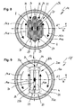
- FIG. 8 is a sixth embodiment of the switchgear segment 1e in the in FIG. 1 shown location and type shown. The following is only to the differences to in FIG. 7 illustrated switchgear segment 1d received. Identical or equivalent elements are in turn provided with the same or at least similar reference numerals.
- the current conductor 2k shown here is in turn designed as a conductor packing of individual conductors, but here also with a third individual conductor 32. As in the fifth embodiment 1d, two adjacent individual conductors 25, 26 and 26, 32 bound each one convection channel 28 laterally. So that the current conductor 2 k has a dielectric behavior as close as possible to a circular conductor, the profile cross sections of the first individual conductor 25 and the third individual conductor 32 each have shorter heights, as the interposed second single conductor 26th
- the heat transfer from the conductor 2k to the insulating gas is at least slightly greater than in the fifth embodiment 1d.
- FIG. 9 is a seventh embodiment of the switchgear segment 1f in the in FIG. 2 shown location and type shown. The following is only to the differences to in FIG. 2 described switchgear segment 1b received. Identical or equivalent elements are in turn provided with the same or at least similar reference numerals.
- the current conductor 2m shown here is again designed as a conductor packing of individual conductors and has a first end region 33 of the current conductor 2m and a second end region 34 of the current conductor 2m lying opposite in the effective direction of the gravitational force 13.
- FIG. 9 are the end portions 33, 34 spotted and shown only stylized.
- Each individual conductor is connected in an electrically conductive manner to its end-region-side ends to a respective rod-shaped molding 35a, 35b, which extend in the longitudinal direction (Y).
- the laterally enlarged mold pieces 35a, 35b with respect to the individual conductors 25, 26 considerably improve the dielectric properties of the current conductor 2m according to the embodiment as compared with the sixth embodiment 1e.
- hatching of the individual conductors 25, 26 and the shaped pieces 35a, 35b has been dispensed with.
- FIG. 10 illustrated, eighth embodiment of the switchgear segment 1g with the conductor 2n corresponds to the structure of the rail package with the individual conductors 25, 26, 32 ago the in FIG. 8 shown embodiment - with the difference that the individual conductors 25, 26, 32 in the end regions 33, 34 electrically with a respective shaped piece 35a, 35b, 35c similar to that in in FIG. 9 described embodiment 1f are equipped.
- Identical or equivalent elements are in turn provided with the same or at least similar reference numerals. For the sake of clarity, hatching of the individual conductors 25, 26, 32 and the molded pieces 35a, 35b, 35c has been dispensed with.
- the shaped pieces 35a, 35b, 35c are ideally adapted in their respective shaped piece cross-section such that they touch a preferably circular envelope 36 of the conductor 2n tangentially at least in sections.
- the envelope profile 36 of the shaped conductor envelopes at the shaped pieces 35a, 35b, 35c has the cross-sectional shape of a dielectrically ideal circle, if the housing 4 likewise has an annular cross-section.
- the decisive profile cross-section in this embodiment is the sum of the individual cross-sections of all individual conductors 25, 26, 32 and of all shaped pieces 35a, 35b, 35c in the XZ plane.
- FIG. 11 and the FIG. 12 illustrate alternative cross-sections and configurations of conductor packages / conductors 2p, 2q, each with two individual conductors.
- the two conductor packages / conductors 2p, 2q are approximately as alternatives to the conductor 2i in FIG. 6 or conductor 2m in FIG. 9 used.
- multi-part conductor 2e are also the individual conductors 25a, 26a of the conductor package 2p constructed in several parts.
- the conductive fittings 35c, 35d are in turn electrically connected to the individual conductors 25a, 26a in the end regions of the conductor.
- the Fittings 35c, 35d aligned flush with the respective first lateral surface portion 9 and second lateral surface portion 10.
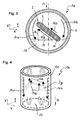
- FIG. 13 is a conductor section 37 of a further embodiment of a current conductor 2r in a spatial representation, wherein the current conductor 2r extends in a longitudinal direction (Y).
- the current conductor 2r is in turn designed as a conductor package with a first individual conductor 25 and a second individual conductor 26.
- the following is just for the differences to in FIG. 9 illustrated current conductor 2m received. Identical or equivalent elements are in turn provided with the same or at least similar reference numerals.
- the end face of the now described current conductor 2r is in reality not a real end face but serves as in FIG FIG. 9 merely to explain the embodiment. With regard to the structure of the two individual conductors 25, 26 is at this point to the description of the current conductor 2m of FIG.
- the current conductor 2r is a current conductor with two one-piece shaped pieces 35d. Upon closer inspection will be off FIG. 13 It can be seen that the current conductors 2r extend over large parts of the conductor length two the Konve mecanicskanal 28 has separate mold halves 42a, 42b, which except in a bridge area connecting them 43 in the FIG.
- the bridge region 43 viewed in the effective direction of the gravitational force, is arranged approximately above the spacer.
Landscapes
- Chemical & Material Sciences (AREA)
- Oil, Petroleum & Natural Gas (AREA)
- Engineering & Computer Science (AREA)
- Power Engineering (AREA)
- Gas-Insulated Switchgears (AREA)
Priority Applications (1)
| Application Number | Priority Date | Filing Date | Title |
|---|---|---|---|
| EP10194900A EP2346131A2 (fr) | 2010-01-18 | 2010-12-14 | Arrangement de conducteurs électriques dans un dispositif isolé au gaz pour améliorer le refroidissement |
Applications Claiming Priority (2)
| Application Number | Priority Date | Filing Date | Title |
|---|---|---|---|
| EP10150959 | 2010-01-18 | ||
| EP10194900A EP2346131A2 (fr) | 2010-01-18 | 2010-12-14 | Arrangement de conducteurs électriques dans un dispositif isolé au gaz pour améliorer le refroidissement |
Publications (1)
| Publication Number | Publication Date |
|---|---|
| EP2346131A2 true EP2346131A2 (fr) | 2011-07-20 |
Family
ID=42200032
Family Applications (1)
| Application Number | Title | Priority Date | Filing Date |
|---|---|---|---|
| EP10194900A Withdrawn EP2346131A2 (fr) | 2010-01-18 | 2010-12-14 | Arrangement de conducteurs électriques dans un dispositif isolé au gaz pour améliorer le refroidissement |
Country Status (3)
| Country | Link |
|---|---|
| EP (1) | EP2346131A2 (fr) |
| KR (1) | KR20110084831A (fr) |
| CN (1) | CN102130428A (fr) |
Cited By (3)
| Publication number | Priority date | Publication date | Assignee | Title |
|---|---|---|---|---|
| WO2013110507A1 (fr) * | 2012-01-23 | 2013-08-01 | Siemens Aktiengesellschaft | Ensemble barre collectrice isolée par un fluide et dotée d'une irrégularité assurant le tourbillonnement du fluide isolant |
| EP2747226A1 (fr) * | 2012-12-20 | 2014-06-25 | ABB Technology AG | Omi-bus de haute-tension d'un générateur avec des moyens de refroidissement améliorées |
| CN105493367A (zh) * | 2013-09-29 | 2016-04-13 | Abb技术有限公司 | 主母线、分支母线、传输转接块和母线组件 |
Families Citing this family (1)
| Publication number | Priority date | Publication date | Assignee | Title |
|---|---|---|---|---|
| CN103971985A (zh) * | 2013-02-01 | 2014-08-06 | 西门子公司 | 真空开关管的接触件以及接触系统 |
Family Cites Families (5)
| Publication number | Priority date | Publication date | Assignee | Title |
|---|---|---|---|---|
| JPS576649B2 (fr) * | 1974-02-27 | 1982-02-05 | ||
| SE7801543L (sv) * | 1978-02-09 | 1979-08-10 | Ssab Svenskt Stal Ab | Rorkabel |
| JPS5721217U (fr) * | 1980-07-14 | 1982-02-03 | ||
| JPS6138361Y2 (fr) * | 1981-05-22 | 1986-11-06 | ||
| JPS5863016A (ja) * | 1981-10-08 | 1983-04-14 | 株式会社東芝 | ガス絶縁管路母線 |
-
2010
- 2010-12-14 EP EP10194900A patent/EP2346131A2/fr not_active Withdrawn
-
2011
- 2011-01-14 KR KR1020110003866A patent/KR20110084831A/ko not_active Abandoned
- 2011-01-18 CN CN2011100277928A patent/CN102130428A/zh active Pending
Non-Patent Citations (1)
| Title |
|---|
| None |
Cited By (4)
| Publication number | Priority date | Publication date | Assignee | Title |
|---|---|---|---|---|
| WO2013110507A1 (fr) * | 2012-01-23 | 2013-08-01 | Siemens Aktiengesellschaft | Ensemble barre collectrice isolée par un fluide et dotée d'une irrégularité assurant le tourbillonnement du fluide isolant |
| EP2747226A1 (fr) * | 2012-12-20 | 2014-06-25 | ABB Technology AG | Omi-bus de haute-tension d'un générateur avec des moyens de refroidissement améliorées |
| CN105493367A (zh) * | 2013-09-29 | 2016-04-13 | Abb技术有限公司 | 主母线、分支母线、传输转接块和母线组件 |
| EP3050183A4 (fr) * | 2013-09-29 | 2017-10-11 | ABB Schweiz AG | Barre omnibus principale, barre omnibus de dérivation, connecteur de transfert et jeu de barres omnibus |
Also Published As
| Publication number | Publication date |
|---|---|
| KR20110084831A (ko) | 2011-07-26 |
| CN102130428A (zh) | 2011-07-20 |
Similar Documents
| Publication | Publication Date | Title |
|---|---|---|
| DE102010013877A1 (de) | Elektrischer Leistungsschalter und Schaltfeld mit Leistungsschalter | |
| DE1803363A1 (de) | Elektrische Mittelspannungsleitung zur Leistungsuebertragung | |
| EP2346131A2 (fr) | Arrangement de conducteurs électriques dans un dispositif isolé au gaz pour améliorer le refroidissement | |
| EP2390978A1 (fr) | Segment d'installations de commutation à haute tension | |
| EP3332464B1 (fr) | Dispositif d'établissement d'une connexion électrique polyphasée et ensemble comportant des dispositifs correspondants | |
| CH322444A (de) | Metallgekapselte elektrische Hochspannungs-Schaltanlage | |
| EP1977489A1 (fr) | Conducteur d'un dispositif électrique, notamment jeu de barres omnibus d'une installation électrique moyenne tension | |
| DE2016911A1 (de) | Geschlossene Sammelschienenleitung | |
| DE102010014005A1 (de) | Schienenkasten und Schienenverteilersystem mit einem Schienenkasten | |
| EP1249910A2 (fr) | Disjoncteur haute-tension pour une installation de commutation à isolation gaseuse | |
| EP1022830B1 (fr) | Section d'une installation haute-tension avec des moyens de refroidissement | |
| EP3474024A1 (fr) | Transformateur de courant pourvu d'isolation fluidique ou en papier huilé pour haute tension | |
| EP0236885B1 (fr) | Interrupteur de puissance à haute tension isolé à gaz comprimé, triphasé et blindé | |
| EP3347958A1 (fr) | Isolateur haute tension pour tension continue, installation haute tension pour courant continu équipée d'un isolateur haute tension pour tension continue et leur utilisation | |
| DE3433757A1 (de) | Stromfuehrende schraubverbindung zwischen zwei rohrfoermigen leitern einer elektrischen anlage, insbesondere einer metallgekapselten hochspannungsschaltanlage | |
| DE3103433C2 (fr) | ||
| DE102013017748A1 (de) | Elektrisches Verbindungselement | |
| EP2118979B1 (fr) | Dispositif de transmission d'energie electrique comportant un boitier d'encapsulage | |
| DE19723441A1 (de) | Koaxialer Schienenverteiler und Verfahren zu seiner Herstellung | |
| DE102010004971A1 (de) | Vorrichtung für eine Schaltanlage | |
| DE3806081C2 (fr) | ||
| DE102010042568A1 (de) | Mehrpolig gasisolierter Sammelschienenabschnitt | |
| EP1407461B1 (fr) | Transformateur de traversee concu pour un dispositif de commutation electrique | |
| WO2007033947A1 (fr) | Ensemble barre collectrice pour une installation de distribution electrique a double face de commande | |
| WO2008012012A1 (fr) | Module de barre collectrice pour une installation de distribution à haute tension isolée par gaz |
Legal Events
| Date | Code | Title | Description |
|---|---|---|---|
| PUAI | Public reference made under article 153(3) epc to a published international application that has entered the european phase |
Free format text: ORIGINAL CODE: 0009012 |
|
| AK | Designated contracting states |
Kind code of ref document: A2 Designated state(s): AL AT BE BG CH CY CZ DE DK EE ES FI FR GB GR HR HU IE IS IT LI LT LU LV MC MK MT NL NO PL PT RO RS SE SI SK SM TR |
|
| AX | Request for extension of the european patent |
Extension state: BA ME |
|
| STAA | Information on the status of an ep patent application or granted ep patent |
Free format text: STATUS: THE APPLICATION IS DEEMED TO BE WITHDRAWN |
|
| 18D | Application deemed to be withdrawn |
Effective date: 20150701 |