EP2346151A1 - Dispositif de conversion de puissance - Google Patents
Dispositif de conversion de puissance Download PDFInfo
- Publication number
- EP2346151A1 EP2346151A1 EP09823203A EP09823203A EP2346151A1 EP 2346151 A1 EP2346151 A1 EP 2346151A1 EP 09823203 A EP09823203 A EP 09823203A EP 09823203 A EP09823203 A EP 09823203A EP 2346151 A1 EP2346151 A1 EP 2346151A1
- Authority
- EP
- European Patent Office
- Prior art keywords
- voltage
- inverter
- value
- frequency
- ripple
- Prior art date
- Legal status (The legal status is an assumption and is not a legal conclusion. Google has not performed a legal analysis and makes no representation as to the accuracy of the status listed.)
- Withdrawn
Links
Images


Classifications
-
- H—ELECTRICITY
- H02—GENERATION; CONVERSION OR DISTRIBUTION OF ELECTRIC POWER
- H02M—APPARATUS FOR CONVERSION BETWEEN AC AND AC, BETWEEN AC AND DC, OR BETWEEN DC AND DC, AND FOR USE WITH MAINS OR SIMILAR POWER SUPPLY SYSTEMS; CONVERSION OF DC OR AC INPUT POWER INTO SURGE OUTPUT POWER; CONTROL OR REGULATION THEREOF
- H02M7/00—Conversion of AC power input into DC power output; Conversion of DC power input into AC power output
- H02M7/42—Conversion of DC power input into AC power output without possibility of reversal
- H02M7/44—Conversion of DC power input into AC power output without possibility of reversal by static converters
- H02M7/48—Conversion of DC power input into AC power output without possibility of reversal by static converters using discharge tubes with control electrode or semiconductor devices with control electrode
- H02M7/53—Conversion of DC power input into AC power output without possibility of reversal by static converters using discharge tubes with control electrode or semiconductor devices with control electrode using devices of a triode or transistor type requiring continuous application of a control signal
- H02M7/537—Conversion of DC power input into AC power output without possibility of reversal by static converters using discharge tubes with control electrode or semiconductor devices with control electrode using devices of a triode or transistor type requiring continuous application of a control signal using semiconductor devices only, e.g. single switched pulse inverters
- H02M7/5387—Conversion of DC power input into AC power output without possibility of reversal by static converters using discharge tubes with control electrode or semiconductor devices with control electrode using devices of a triode or transistor type requiring continuous application of a control signal using semiconductor devices only, e.g. single switched pulse inverters in a bridge configuration
- H02M7/53871—Conversion of DC power input into AC power output without possibility of reversal by static converters using discharge tubes with control electrode or semiconductor devices with control electrode using devices of a triode or transistor type requiring continuous application of a control signal using semiconductor devices only, e.g. single switched pulse inverters in a bridge configuration with automatic control of output voltage or current
- H02M7/53875—Conversion of DC power input into AC power output without possibility of reversal by static converters using discharge tubes with control electrode or semiconductor devices with control electrode using devices of a triode or transistor type requiring continuous application of a control signal using semiconductor devices only, e.g. single switched pulse inverters in a bridge configuration with automatic control of output voltage or current with analogue control of three-phase output
-
- H—ELECTRICITY
- H02—GENERATION; CONVERSION OR DISTRIBUTION OF ELECTRIC POWER
- H02M—APPARATUS FOR CONVERSION BETWEEN AC AND AC, BETWEEN AC AND DC, OR BETWEEN DC AND DC, AND FOR USE WITH MAINS OR SIMILAR POWER SUPPLY SYSTEMS; CONVERSION OF DC OR AC INPUT POWER INTO SURGE OUTPUT POWER; CONTROL OR REGULATION THEREOF
- H02M7/00—Conversion of AC power input into DC power output; Conversion of DC power input into AC power output
- H02M7/42—Conversion of DC power input into AC power output without possibility of reversal
- H02M7/44—Conversion of DC power input into AC power output without possibility of reversal by static converters
- H02M7/48—Conversion of DC power input into AC power output without possibility of reversal by static converters using discharge tubes with control electrode or semiconductor devices with control electrode
-
- H—ELECTRICITY
- H02—GENERATION; CONVERSION OR DISTRIBUTION OF ELECTRIC POWER
- H02P—CONTROL OR REGULATION OF ELECTRIC MOTORS, ELECTRIC GENERATORS OR DYNAMO-ELECTRIC CONVERTERS; CONTROLLING TRANSFORMERS, REACTORS OR CHOKE COILS
- H02P27/00—Arrangements or methods for the control of AC motors characterised by the kind of supply voltage
- H02P27/04—Arrangements or methods for the control of AC motors characterised by the kind of supply voltage using variable-frequency supply voltage, e.g. inverter or converter supply voltage
- H02P27/06—Arrangements or methods for the control of AC motors characterised by the kind of supply voltage using variable-frequency supply voltage, e.g. inverter or converter supply voltage using DC to AC converters or inverters
-
- H—ELECTRICITY
- H02—GENERATION; CONVERSION OR DISTRIBUTION OF ELECTRIC POWER
- H02M—APPARATUS FOR CONVERSION BETWEEN AC AND AC, BETWEEN AC AND DC, OR BETWEEN DC AND DC, AND FOR USE WITH MAINS OR SIMILAR POWER SUPPLY SYSTEMS; CONVERSION OF DC OR AC INPUT POWER INTO SURGE OUTPUT POWER; CONTROL OR REGULATION THEREOF
- H02M5/00—Conversion of AC power input into AC power output, e.g. for change of voltage, for change of frequency, for change of number of phases
- H02M5/40—Conversion of AC power input into AC power output, e.g. for change of voltage, for change of frequency, for change of number of phases with intermediate conversion into DC
- H02M5/42—Conversion of AC power input into AC power output, e.g. for change of voltage, for change of frequency, for change of number of phases with intermediate conversion into DC by static converters
- H02M5/44—Conversion of AC power input into AC power output, e.g. for change of voltage, for change of frequency, for change of number of phases with intermediate conversion into DC by static converters using discharge tubes or semiconductor devices to convert the intermediate DC into AC
Definitions
- the present invention relates to electrical conversion apparatuses that convert a direct current (DC) electric power to a variable-frequency, variable-voltage alternating current (AC) electric power, and in particular to an AC-AC electrical power conversion apparatus that includes a converter and an inverter that converts a DC output electric power generated from the converter into a variable-frequency, variable-voltage AC electric power.
- DC direct current
- AC variable-voltage alternating current
- a PWM converter for use in an electric railway vehicle receives an AC input from a single-phase AC power source between an overhead line and a rail by way of a pantagraph, a transformer and the like, to convert the power from the source into power of a predetermined DC voltage.
- a capacitor for smoothing the voltage is provided on the DC side of the PWM converter, and an inverter for driving an induction motor is connected to the capacitor. The voltage across the capacitor is detected by a voltage detector, thereby sensing a DC input voltage that is to be applied to the inverter.
- a current detector is provided on the AC side of the inverter.
- a reference output frequency of the inverter is created by adding together, using an adder, a rotation frequency-which is an output of rotation frequency detecting means of the induction motor-and a reference slip frequency-which is an output of a slip frequency control.
- An output current value detected by the current detector is provided to current root-mean-square (RMS) value calculating means, thereby calculating a current RMS value.
- the current RMS value is transmitted to the adder together with a command current value, thus calculating the reference slip frequency using frequency control means.
- a DC input voltage to the inverter is detected by a voltage detector and only its ripple component is derived from voltage ripple component detecting means.
- the DC input voltage to the inverter is also input to DC voltage component detecting means and only its DC component is derived therefrom.
- a divider divides the ripple component by the DC component, to calculate a ripple factor of the DC input voltage, and a multiplier multiples the ripple factor by a reference inverter frequency to calculate an amount of inverter frequency correction.
- the inverter frequency is calculated by adding the amount of reference inverter frequency to the amount of inverter frequency correction using an adder.
- This inverter frequency is provided to voltage control means, and a PWM control circuit in turn provides a PWM control signal to the inverter (refer to Patent Document 1, Fig. 1 and its corresponding description).
- Non-Patent Document 1 has verified the advantageous effect of Patent Document 1 through experiments. Further, Non-Patent Document 1 ( Fig. 7 ) provides description of a ripple characteristic of a DC power source in a PWM converter for use in a railway vehicle.
- Non-Patent Document 1 describes based on a beat rate showing how many times a fluctuation range of an inverter output current is greater than that in situations where no beat occurs
- Non-Patent Document 1 explains that in order to achieve the suppression effect such that the beat rate is 1.2 times or less, the ripple factor of DC voltage (a ratio of a DC ripple magnitude over a DC average voltage) is reduced to 10 % or less.
- the capacitance of DC capacitor must be determined to be approximately 30 mF or more (3750 ⁇ F per motor) per 8 motors (output rating of approx. 3000 kW), for instance.
- the ripple factor of the DC input voltage is calculated by dividing its ripple component by its DC component, and the amount of inverter frequency correction is calculated by multiplying the ripple factor by the reference inverter frequency, whereby the inverter frequency is adjusted according to the ripple of the DC input voltage, thereby enabling the current and torque ripple to be reduced.
- a problem with the apparatus of Patent Document 1 is that in order to achieve an effect of reducing the predetermined beat phenomenon, a constraint is applied such that the capacitance of a DC capacitor is determined, as described in Non-Patent Document 1, so that the ripple of the DC voltage can be reduced.
- the capacitance of the DC capacitor is determined by limiting the ripple component of DC voltage to 10 % or less thereof in the frequency and therefore a problem is that the capacitance of DC capacitor is increased because of the particular frequency point where the beating phenomenon is maximized.
- the present invention is directed to overcome the above problem and an object thereof is to reduce the capacitance of DC capacitor of an electrical conversion apparatus, as well as to suppress a motor current ripple on the output side of the electrical conversion apparatus and associated torque ripple.
- An electrical power conversion apparatus comprises:
- An electrical power conversion apparatus comprises:
- Fig. 1 is a block diagram showing an example of a configuration of an electrical power conversion apparatus according to Embodiment 1 of the present invention.
- the electrical power conversion apparatus includes a converter 2 that converts an AC power from a single-phase AC power source 1 into a DC power, a capacitor 3 that stores the DC power produced by rectifying the AC power using the converter 2, an inverter 4 that converts the DC power stored in the capacitor 3 into a three-phase AC power of arbitrary frequency.
- the inverter 4 drives the induction machine 5 that is an AC rotating machine.
- the converter 2 controls AC power from the AC power source 1 of the commercial frequency in a PWM (pulse width modulation) mode to convert it into the DC power.
- the inverter 4 controls a low speed range of operation in a variable-voltage/variable frequency (VVVF) mode and a high speed range of operation in a constant-voltage/variable-frequency (CVVF) mode.
- VVVF variable-voltage/variable frequency
- CVVF constant-
- Current detection units 6a, 6b and 6c which are current measuring instruments on the AC side, detect phase currents iu, iv and iw that flow in an induction machine 5, respectively.
- Fig.1 describes the current detection units 6a, 6b and 6c on the AC side that detect by means of CT or the like the currents flowing through connection lines that connect the inverter 4 to the induction machine 5.
- the phase currents may be detected through another known technique, using currents flowing through the electrical power conversion apparatus, such as bus currents.
- a current detection unit 6c for the w-phase may be omitted.
- a voltage control unit 7 determines the magnitude of an AC voltage generated from the inverter 4 based on a torque current command value Iq, a magnetic flux current command value Id, and a rotation angular frequency ⁇ of the AC rotating machine.
- the angular frequency ⁇ may be based on speed information derived from a speed sensor mounted on the induction machine 5.
- the speed command value ⁇ * may be used as the angular frequency ⁇ .
- the angular frequency ⁇ may be an estimated speed value that is calculated in a speed sensorless control in which a speed sensor is not mounted.
- Fig. 2 is a diagram illustrating a configuration of a ripple detection unit 8 in the electrical power conversion apparatus according to Embodiment 1 of the present invention.
- the ripple detection unit 8 which detects a ripple component that accompanies AC-DC conversion by the converter 2, includes a root-mean-square (RMS) power calculation unit 11 and a band-pass filter 12.
- RMS root-mean-square
- the RMS power calculation unit 11 calculates a RMS power P that is to be generated from the inverter 4 by summing together respective values calculated by multiplying Vu* by iu, Vv* by iv, and Vw* by iw, using phase currents iu, iv and iw that are detected with the current detection unit 6 and voltage command values Vu*, Vv*, Vw* that are calculated with the voltage control unit 7 and are to be generated from the inverter 4.
- the band-pass filter 12 filters out a ripple component of the RMS power P generated from the RMS power calculation unit 11.
- the RMS power calculation unit 11 calculates the RMS power P based on the following equation.
- the RMS power which is an output from RMS power calculation unit 11, includes a ripple component of a motor current resulting from the ripple component that accompanies AC-DC conversion by the converter 2. Note that the RMS power may be calculated using voltage and current values in a rotating orthogonal coordinate system.
- a band-pass filter 12 in Fig. 2 derives only the ripple component contained in the RMS power P and accompanies AC-DC conversion by the converter 2.
- the AC power source 1 is a single-phase power source of the commercial frequency
- the frequency of the single-phase power source is 60Hz or 50Hz in Japan.
- the ripple component that accompanies AC-DC conversion by the converter 2 is 120 Hz or 100Hz in frequency, which is twice the frequency of the single-phase AC power source.
- the band-pass filter 12 is configured assuming that the frequency of the single-phase AC power source is, for example, 60 Hz.
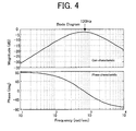
- Fig. 3 shows a diagram illustrating the band-pass filter.
- the band-pass filter 12 is configured by a combination of a high-pass filter (HPF) 13 that passes therethrough frequencies higher than those corresponding to a time constant T 1 , which is a first time constant, and a low-pass filter (LPF) 14 that passes therethrough frequencies higher than those corresponding to a time constant T 2 , which is a second time constant.
- T 1 1 / 2 ⁇ ⁇ ⁇ 60
- T 2 1 / 2 ⁇ ⁇ ⁇ 180
- a gain characteristic and a phase characteristic in a frequency generated when the band-pass filter 12 of Fig. 3 is configured with the time constants given by Expression (2) and (3), is as shown in Fig. 4 .
- the characteristics shown in Fig. 4 indicates that the gain characteristic is one that passes the frequencies around 120 Hz with almost no attenuation. For that reason, the band-pass filter 12 can derive the 120 Hz component-a ripple component that accompanies AC-DC conversion by the converter 2-to output a ripple component P_BEET.
- the electrical power conversion apparatus includes a DC voltage command generation unit 16 and a DC voltage control unit 17.
- the DC voltage command generation unit 16 is supplied with the rotation angular frequency ⁇ of the AC rotating machine, to generate a command value Vc* for a DC voltage Vc that is a voltage across the capacitor 3 to be charged by the converter 2 and that is measured by a DC voltage detection unit 15 that is a voltage measuring instrument.
- the DC voltage control unit 17 controls the converter 2 in accordance with the command value Vc*.
- the DC voltage command generation unit 16 increases the DC voltage only during a time when the angular frequency ⁇ generated from the inverter 4 has much influence, resulting from the ripple of the DC power, on a torque and the like.
- an input power Pin to the converter 2 is represented by the following expression.
- the capacitance of the capacitor 3 is represented as C and the voltage across the capacitor 3, as Vc, and if it is assumed that no influence due to the ripple of the voltage Vc across the capacitor 3 occurs on the inverter 4 side, the following equation holds.
- the voltage Vc across the capacitor 3 is called DC voltage.
- Expression (10) or Equation (3) assumes that a value of (E x I)/(2 ⁇ C x Vcav 2 ) is sufficiently smaller than a value of one, and an approximation is used, such that ⁇ (1 + ⁇ ) ⁇ 1 + ⁇ /2 in terms of symbol ⁇ that is sufficiently smaller than a value of one.
- the second terms of Equation (3) represents a ripple component of the DC voltage Vc.
- the ripple component represents a frequency of twice the power source frequency, and it is seen that its magnitude is reversely proportional to the capacitor capacitance C and the average value of the DC voltage Vc.
- the value (E x I) represents a power to be supplied to the converter 2, and is maintained constant even though the DC voltage Vc varies.
- a current ic flowing in the DC capacitor is obtained based on the following equation.
- Equation (12) or Equation (5) shows that if a value of (E x I)/2 ⁇ C is constant and when the average value Vcav of the DC voltage Vc is increased, the ripple factor can be reduced inversely proportionally to the square of the value Vcav. Further, Equation (5) indicates that when the ripple factor is assumed to remain the same, the capacitor capacitance C can be reduced if the average value Vcav of the DC voltage Vc is increased. Equation (5) shows that, by increasing the average value Vcav of the DC voltage Vc by, for instance, 20 % from 3000 V to 3600 V, the capacitor capacitance, provided that the same ripple factor is applied, can be reduced approximately 30 % (more specifically 30.6 %). Equations (3) and (5) are theoretical equations under assumption that the ripple of the DC voltage Vc has no influence on the output side of the inverter 4; however, they hold in a substantially similar fashion even when the voltage generated from the inverter 4 contains a ripple component.
- the inverter When the inverter is operated in a one-pulse mode, the influence of the DC voltage on the switching device is reduced in comparison with a multi-pulse mode, even though the DC voltage is increased to more than the rated voltage, as will be described in detail later.
- Fig. 5 is a diagram showing the DC current command generation unit in the electrical power conversion apparatus according to Embodiment 1 of the present invention.
- the DC voltage command generation unit 16 is configured with an absolute value unit 18 that converts the angular frequency ⁇ to its absolute value, and a DC voltage value set table 19.
- the absolute value unit 18 takes an absolute value of the angular frequency ⁇ so that only a positive value is selected in order to simplify the DC voltage value set table 19 because the angular frequency ⁇ to be supplied is assigned a positive or negative sign.
- the angular frequency ⁇ that turns the absolute value is shown on the horizontal axis and a DC voltage command value to be generated, on the vertical axis.
- the DC voltage value set table 19 as shown in Fig.
- the DC voltage is at its maximum voltage of 3600 V in a range (in the present embodiment, a range of 115 Hz to 125 Hz, inclusive) including the frequency that is twice (in this case, the frequency is at 120 Hz; however, 100 Hz may in some cases be used depending on an AC power source) the frequency of the AC power source where the voltage across the capacitor 3 contains a ripple component, in other words, there is present a large beating phenomenon.
- the DC voltage is increased progressively
- the subsequent range a range of 125 Hz to 180 Hz, inclusive
- the DC voltage is increased in the predetermined range (a range of 60 Hz to 180 Hz, inclusive).
- the range where the DC voltage becomes a maximum is from 115 Hz to 125 Hz, inclusive.
- the predetermined range in which the DC voltage is increased more than usual is determined to be within a range where a beat rate ⁇ is permissible.
- the beat rate is based on the following equation that is defined in Non-Patent Document 1.
- ⁇ b - a / a
- numeral b is a fluctuation range of an inverter output current
- numeral a is a fluctuation range of an output frequency of the inverter output current.
- the upper limit value of a predetermined frequency range where the DC voltage is increased more than usual needs to be a value where a beat rate at a normal DC voltage is permissible. Ditto for the lower limit value of the predetermined frequency range.
- the predetermined range may be determined based on another indicator other than the beat rate. It also may be determined in whatever manner that allows a ripple component of the RMS power generated from an inverter to be controlled within the allowable range.
- the frequency range where the DC voltage is increased more than usual is suitably determined in consideration of values such as the beat rate ⁇ that is allowable, a target value of the ripple factor ⁇ at the frequency of twice the AC power source frequency, and a ratio of a normal value over a maximum value of the DC voltage.
- the beat rate ⁇ is 1.2 or less
- the ripple factor at the frequency of twice the AC power source frequency is 10 %
- the ratio of a normal value over a maximum value of the DC voltage is 1.2
- the table data are configured such that the DC voltage command value Vc* does not exceed an over-voltage set value of the inverter 4.
- the maximum value of increasing the DC voltage, 3600 V is determined in consideration of a rated voltage and characteristic of a switching device constituting the inverter 4.
- the DC voltage control unit 17 receives the DC voltage command value Vc* that is an output from the DC voltage command generation unit 16 and the DC voltage Vc detected by the DC voltage detection unit 15.
- the control unit 17 calculates the difference between the DC voltage command value Vc* and the DC voltage Vc, to control the converter 2 so as to produce zero voltage difference between them.
- the voltage control unit 7 calculates a slip angular frequency command value ⁇ s* using the torque current command value Iq* and the magnetic flux current command value Id* based on Expression (13).
- ⁇ s * Iq * / Id * Rr / Lr
- the inverter 4 calculates an inverter angular frequency ⁇ inv that corresponds to the frequency of the voltage generated from the inverter 4, by subtracting from a sum of the slip angular frequency command value ⁇ s* and the frequency ⁇ an amount of correction F_BEET obtained by multiplying a predetermined coefficient Kf by a ripple amount P_BEET calculated with the ripple detection unit 8. Namely, the inverter angular frequency ⁇ inv is calculated based on Expression 14.
- a d-axis voltage command value Vd* and a q-axis voltage command value Vq* on two rotational axes can be calculated using the inverter angular frequency ⁇ inv, the torque current command value Iq* and the magnetic flux current command value Id*, based on Expression (16) and Expression (17).
- Vd * Rs Id * - ⁇ inv ⁇ Ls Iq *
- Vq * Rs Iq * + ⁇ inv Ls Id *
- Vu * Vv * Vw * Vd * 2 + Vq * 2 ⁇ cos ⁇ v cos ⁇ v - 2 3 ⁇ ⁇ cos ⁇ v + 2 3 ⁇ ⁇
- the inverter 4 performs DC-AC conversion based on the three-phase voltage command values Vu*, Vv* and Vw*, calculated based on Expression 20 or Equation (7) and obtained from the voltage control unit 7.
- the frequency of a voltage generated from the inverter 4 based on the ripple component derived from the ripple detection unit 8 is corrected, thus enabling reductions of the motor current ripple on the output side of the inverter 4 and associated torque ripple.
- ripple component P_BEET derived from the ripple detection unit 8 in synchronization with the ripple of the motor current on the output side of the inverter 4 and associated torque ripple is positive in sign
- adjustments are made so as to reduce the inverter angular frequency ⁇ inv, and the frequency of the three-phase voltage command values Vu*, Vv* and Vw* that are generated from the voltage control unit 7 are reduced.
- the ripple component P_BEET derived from the ripple detection unit 8 is negative in sign
- adjustments are made so as to increase the inverter angular frequency ⁇ inv and the frequencies of the three-phase voltage command values Vu*Vv* and Vw* that are generated from the voltage control unit 7 are increased. This allows for the control operation in response to the ripple of the motor current on the output side of the inverter 4 and associated torque ripple, thereby reducing the motor current ripple and the torque ripple.
- Fig. 7 is a set of graphs showing an effect of reducing a torque ripple by the electrical power conversion apparatus according to Embodiment 1 of the present invention.
- Fig. 7(a) shows a torque waveform generated by implementing Embodiment 1
- Fig. 7(b) showing a torque waveform generated when the reduction of the torque ripple is not controlled.
- the torque waveforms shown in Fig. 7 are generated by simulations in which the DC voltage is set at 3600 V and the inverter frequency at 115 Hz.
- the torque waveform ripples at 120 Hz, which is twice the single-phase power sour frequency
- Fig. 7(a) where Embodiment 1 is implemented it can be recognized that the torque waveform has little ripple.
- Embodiment 1 by implementing Embodiment 1 the influence of the ripple that accompanies the AC-DC conversion by the converter is detected as the ripple component contained in the RMS power of the inverter, thus correcting the frequency of the voltage generated from the inverter, whereby an advantageous effect is provided in that the torque ripple and the like is reduced. Further, by increasing the DC voltage during a time when the inverter generates the output frequency in which the beating phenomenon becomes large, that is, only during a time when the voltage across the capacitor contains a ripple component, the capacitance of the capacitor can be lowered which is necessary for reducing the beating phenomenon to within the permissible range. Consequently, compactness and cost reduction of electrical power conversion apparatus can be achieved. In addition, this is also true for other embodiments.
- Fig. 8 is a block diagram showing an example of a configuration of an electrical power conversion apparatus according to Embodiment 2 of the present invention.
- Fig. 9 is a diagram illustrating a configuration of a ripple detection unit in the electrical power conversion apparatus according to Embodiment 2 of the present invention.
- a ripple detection unit 8A, a voltage control unit 7A and a DC voltage command generation unit 16A are different compared to those in Embodiment 1.
- a RMS power is calculated from respective three-phase command values and respective three-phase currents, and a ripple component is derived from the RMS power, to correct a frequency based on the ripple component.
- the ripple detection unit 8A calculates a RMS power from dq-axis voltage command values and dq-axis currents, and the voltage control unit 7A corrects an amplitude of the current command value according to the ripple component of the RMS power.
- the DC voltage command generation unit 16A operates so as to control the DC voltage according to the calculated value of the RMS power, and adjust the DC voltage to its normal value when the RMS power P is small in quantity and within a range where its beating phenomenon is permissible. Note that configurations other than those described are similar to those in Embodiment 1 and pertinent figures use the same reference numerals as well. Only the differences will be described herein.
- the ripple detection unit 8A that detects the ripple component that accompanies AC-DC conversion by the converter 2 includes a phase calculation unit 20, a three-phase to dq-axis conversion calculation unit 21 and a RMS power calculation unit 11A.
- the phase calculation unit 20 receives the angular frequency ⁇ as an input, to calculate the phase ⁇ by integrating, as shown in Equation (6), ⁇ inv that is to be calculated as will be described later.
- the three-phase to dq axis conversion calculation unit 21 calculates d-q axis currents Id and Iq by means of the phase currents iu, iv and iw detected by the current detection unit 6, using the phase ⁇ .
- the RMS power calculation unit 11A calculates the RMS power P using the dq-axis currents Id and Iq calculated by the three-phase to dq-axis conversion calculation unit 21 and the dq-axis voltage command values Vd* and Vq* calculated by the voltage control unit 7A, based on the following expression.
- the RMS power calculation unit 11A includes multipliers 22a and 22b, and an adder 23, in which a value obtained by multiplication of Vd* and Id using the multiplier 22a and a value obtained by multiplication of Vq* and Iq using the multiplier 22b are summed together using the adder 23 to thereby generate the output of the adder 23 as the RMS power P.
- the RMS power P which is an output of the RMS power calculation unit 11A, contains a motor current ripple and a torque ripple component resulting from the ripple component that accompanies the AC-DC conversion by the converter 2.
- the RMS power P calculated using the RMS power calculation unit 11A is input to the band-pass filter 12, and the output P_BEET from the band-pass filter is input to the voltage control unit.
- the subtractor 24 subtracts the output P_BEET of the band-pass filter from the output of the RMS power calculation unit 11A, to output to the DC voltage command generation unit 16A the subtraction result as a RMS power P that does not contains the ripple component.
- the voltage control unit 7A calculates the slip angular frequency command value ⁇ s* from the torque current command value Iq* and the magnetic flux current command value Id*, using the motor constant of the induction machine. Namely, the slip angular frequency command value ⁇ s* is calculated using Expression (13) as with Embodiment 1.
- the inverter 4 calculates the inverter angular frequency ⁇ inv that corresponds to a frequency of the voltage to be generated. That is, the inverter angular frequency ⁇ inv is calculated based on Expression (22) shown below.
- ⁇ inv ⁇ + ⁇ s *
- the d-axis voltage command value Vd* and the q-axis voltage command value Vq* on the two rotating axes can be calculated from the inverter angular frequency ⁇ the torque current command value Iq* and the magnetic flux current command value Id*. Namely, the d-axis voltage command value Vd* and the q-axis voltage command value Vq* are calculated based on Expression (16) and Expression (17) as with Embodiment 1. Since the voltage phase ⁇ v of the voltage command value is slightly advanced with respect to the phase ⁇ , it is calculated based on Expression (19) as with Embodiment 1.
- the three-phase voltage command values Vu*, Vv* and Vw* are calculated based on Expression (21) from the voltage phase ⁇ v obtained using Expression (19), the d-axis voltage command value Vd* and the q-axis voltage command value Vq*.
- the amplitudes of the three-phase voltage command values are reduced by a correction amount V_BEET obtained by multiplying the ripple component P_BEET of the RMS power by a coefficient Kv.
- Vu * Vv * Vw * Vd * 2 + Vq * 2 - V_BEET ⁇ cos ⁇ v cos ⁇ v - 2 3 ⁇ ⁇ cos ⁇ v + 2 3 ⁇ ⁇ 23
- V_BEET Kv P_BEET 24
- the DC voltage command generation unit 16A receives the RMS power P, which is ripple-free and the output from the ripple detection unit 8A, and the angular frequency ⁇ .
- the absolute value unit 18 and the DC voltage value set table 19 are the same as those in Embodiment 1.
- the purpose of the DC voltage command generation unit 16A according to Embodiment 2 is to reduce the burden on the switching device constituting the inverter 4 by varying an amplitude for increasing the voltage according to the RMS voltage, in addition to limiting a period of time of increasing the DC voltage, more than that in Embodiment 1.
- the present embodiment is based on the fact that the beating phenomenon varies depending on a power or torque generated by the motor, that is, the greater the power at the same speed, the larger the beating phenomenon becomes. Conversely, when the power is small, its ripple factor is within the allowable range even if the DC voltage is at the rated voltage.
- Fig. 7 of Non-Patent Document 1 also shows that when the voltage is constant, the larger the output from the converter, the larger the ripple factor becomes.
- An absolute value unit 18b of the DC voltage command generation unit 16A receives as an input the RMS power P having the positive or negative signs, to take the absolute value of the RMS power P and then to generate the power P as a RMS power value P1.
- a divider 25 divides the value P1 by a predetermined value (for instance, a maximum power) to output the coefficient Kp.
- the coefficient Kp is definitely limited to within the range 0 ⁇ Kp ⁇ 1 by a limiter 26.
- a multiplier 27 performs multiplication of an output value of the limiter 26 by an output value of the DC voltage value set table 19, and the DC voltage command value Vc* thereby results in a value considered for the RMS power.
- a limiter 28 performs the voltage limiting function so that the DC voltage command value Vc* falls into the range of 3000 V to 3600 V, inclusive. Since, according to Expression (12) or Equation (5), the ripple factor is proportional to the RMS power output by the inverter and reversely proportional to the DC voltage squared, and if the coefficient Kp is made proportional to the square root of the RMS power, the ripple factors are substantially the same regardless of the magnitude of the RMS power so long as the RMS power is large.
- the DC voltage command value increases as the RMS power increases; however, it is expected that a similar advantageous effect is provided also by increasing the DC voltage command value when a value(s) other than the RMS power-such as the current value, the command torque value, the torque current command value, or the torque current value -increase(s). This is true for embodiments below.
- Embodiment 2 the advantageous effect is provided in that an influence resulting from the ripple that accompanies the AC-DC conversion by the converter is detected as a ripple component contained in the RMS power, thus correcting the amplitude of the voltage generated from the inverter, whereby the torque ripple and the like are reduced.
- the DC voltage is made to be a normal value
- the RMS power is greater than the predetermined value and if the RMS power is large
- the DC voltage value is made to increase, thereby providing an advantageous effect in that the burden on the switching device constituting the inverter can be reduced in addition to reduction of the capacitor capacitance. Consequently, another advantageous effect is provided in that compactness and cost reduction of an electrical power conversion apparatus is achieved.
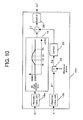
- Fig. 11 is a block diagram showing an example of a configuration of an electrical power conversion apparatus according to Embodiment 3.
- Embodiment 3 is different only in a DC voltage command generation unit 16B from Embodiment 2.
- conditions where the DC voltage is controlled according to a value of the calculated RMS power is further limited to when the RMS power has a positive value, and then the DC voltage value set table 19 is executed.
- increasing the DC voltage is limited to only the time during power operation, and during regeneration operation the DC voltage is fixed at a rated voltage of 3000 V.
- present embodiment is to reduce the beating phenomenon to small size during regeneration operation in comparison with power operation, and to achieve more energy saving by transferring as much energy as possible back to the AC power source, from the viewpoint of energy conservation during regeneration operation.
- configurations other than those described are similar to those in Embodiment 2 and pertinent figures use the same reference numerals as well. Only the differences will be described herein.
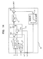
- Fig. 12 is a diagram showing a DC current command generation unit in the electrical power conversion apparatus according to Embodiment 3 of the present invention.
- a limiter 29 In comparison with Fig. 10 in Embodiment 2, added are a limiter 29, a comparator 30, and a switching unit 31. If the RMS power P is greater than zero, that is, during power operation, the comparator 30 generates an output signal of 1, so that the switching unit 31 is set to a position A. When the RMS power P is zero or less, that is, during coasting or regeneration operation, the comparator 30 further generates an output signal of zero, so that the switching unit 31 is set to a position B.
- the limiter 29 which is connected to a contact of the position B of the switching unit 31, performs the voltage limiting function to prevent the DC voltage from becoming more than or less than 3000 V.
- the signal for switching between settings A and B of the switching unit 31 gains the same advantageous effect not only for the RMS power, but also the torque command, power operation command, or regeneration operation (braking) command.
- the DC voltage command generation unit 16B includes the comparator 30, the limiter 29 and the switching unit 31, so that increasing the DC voltage is limited only to the time during power operation and the DC voltage during regeneration operation is fixed at a rated voltage of 3000 V.
- the RMS power is small in amount, the DC voltage remains unchanged at the normal value even during power operation, and even when the RMS power is great in amount, the magnitude of increasing the DC voltage is caused to vary according to the RMS power; however, even by increasing the voltage during power operation independently of the magnitude of the RMS power, a similar advantageous effect is achieved if the DC voltage is not caused to increase.
- Fig. 13 is a block diagram showing an example of a configuration of an electrical power conversion apparatus according to Embodiment 4.
- Fig. 14 is a diagram showing a ripple detection unit in the electrical power conversion apparatus according to Embodiment 4 of the present invention.
- the differences in Embodiment 4 when compared to Embodiment 2 are a ripple detection unit 8B and a DC voltage command generation unit 16C.
- the ripple detection unit 8B includes the three-phase to dq-axis conversion unit 21, the phase calculation unit 20, the RMS power calculation unit 11A and the band-pass filter 12, and additionally includes a correction gain calculation unit 32 that receives the angular frequency ⁇ as an input, to calculate a correction gain k, and a multiplier 33 that multiplies the correction gain k, which is an output from the correction gain calculation unit 32, by an output value of the band-pass filter 12.
- the correction gain k is caused to vary with the angular frequency ⁇ and then may be determined using the table data, or may be provided in the form of a mathematical function. In particular, the correction gain is determined to become a maximum before the ripple frequency component of 120 Hz, for instance. Further, if the correction gain is determined zero, then no correction will be made, which provides an advantageous effect in that, by varying the correction gain with respect to the angular frequency ⁇ , it is determined whether or not a correction is to be made, or if actually made, how much of the correction is required can be varied according to the angular frequency ⁇ .
- Fig. 15 is a diagram showing the DC voltage unit command generation 16C in the electrical power conversion apparatus according to Embodiment 4 of the present invention.
- the ripple detection unit 16C is configured with an absolute value unit 18 that converts the angular frequency ⁇ to its absolute value, and a DC voltage value set table 19B. Because the angular frequency ⁇ to be supplied is assigned a positive or negative sign, the absolute value unit 18 converts the angular frequency ⁇ to the absolute value so that only a positive value is selected in order to simplify the DC voltage value set table 19B.
- the angular frequency ⁇ that has turned the absolute value is shown on the horizontal axis and a DC voltage command value to be generated, on the vertical axis.
- the angular frequency ⁇ that has turned the absolute value is shown on the horizontal axis and a DC voltage command value to be generated, on the vertical axis.
- the DC voltage is at its maximum voltage of 3300 V in a predetermined range (a range of 115 Hz or more in the present embodiment) including the frequency that is twice (in this case, the frequency is at 120 Hz; however, 100 Hz may in some cases be used depending on an AC power source) the AC power source frequency in which there is present a large beating phenomenon; and in the previous range, the DC voltage is increased progressively.
- An advantageous effect is that keeping the voltage high also in a range of 120 Hz or more eliminates operation of reducing the DC voltage, and another advantageous effect is that a loss in a high speed range at 120 Hz or more can be reduced because increasing the voltage reduces the motor current flowing through the motor.
- the output voltage of the inverter 4, that is, a motor voltage Vm is controlled so that a value of Vm/ ⁇ is substantially constant, in a range where the frequency ⁇ of the inverter 4 is above zero and under the predetermined angular frequency ( ⁇ 1) (i.e., a range of 0 ⁇ ⁇ ⁇ ⁇ 1).
- ⁇ 1 angular frequency at which the voltage reaches the maximum value.
- the value of ⁇ 1 is normally smaller than a frequency corresponding to twice the AC power source frequency. In a range where the angular frequency ⁇ is larger than ⁇ 1, the motor voltage Vm is fixed at its maximum value, and only the frequency varies.
- Vm ⁇ ⁇ 6 / ⁇ Vc
- the switching device constituting the inverter 4 employs an insulated gate bipolar transistor (IGBT) having a turn-on and off ability.
- IGBT insulated gate bipolar transistor
- a peak value Vp of a collector-emitter voltage waveform Vce of the IGBT device, shown when the device shown in Fig. 16 interrupts a current I is represented empirically by the following equation.
- Vp Vc + I ⁇ L / C where L is an inductive value of IGBT stray inductance, and C is a stray capacitance of IGBT stray capacitor.
- the one pulse mode is small compared to a multi-pulse (asynchronous) mode.
- the IGBT interrupts the current at its ripple peak value.
- the maximum value of current, Ip to be interrupted by the IGBT in the multi-pulse (asynchronous) mode slightly varies depending on factors such as the motor constant of induction machine, a modulation index of the output voltage generated from the inverter 4, and a length of wiring between the inverter 4 and the induction machine
- an interrupting current Iq corresponding to when the IGBT device interrupts the current once per cycle is represented empirically as shown below, if the fundamental wave RMS value of the motor current is designated Im.
- Iq 0.7 ⁇ ⁇ ⁇ 2 Im In Expression (28) and Expression (29), if no variation of the value Im is assumed to occur in any pulse mode, the following equation hold: Ip ⁇ 2.1 Iq
- the pulse mode is transferred to the one pulse mode, the amount of overcharging I x ⁇ (L/C) in Expression 27 becomes smaller and even if the DC voltage Vc is increased, the peak value Vp of the IGBT collector-emitter voltage does not increase accordingly.
- the inductive value L of the stray inductance of IGBT is approximately 3.0 ⁇ H, and the stray capacitance C of the stray capacitor is in the range of approximately 1.5 ⁇ H to 3.0 ⁇ H.
- ⁇ (L/C) in Equation (27) results in a value of ⁇ 2 ⁇ 1.41. Even if the DC voltage Vc is determined 3300 V as long as the current I interrupted by the IGBT is 200 A or less, the Vp calculated based on Expression (27) will not exceed 3600 V (the maximum value of voltage applicable to the IGBT).
- the Vp results in the order of 3450 V, thereby reducing an influence on the IGBT device.
- the voltages 3600 V and 3300 V are examples and those voltages are determined with considerations of a characteristics and service conditions of a switching device.
- the DC voltage in the low speed range is set to its normal value, and even when the voltage is increased in a range above the speed range where the beating phenomenon occurs, the withstand voltage of the switching device constituting the inverter 4 does not need to be increased if the DC voltage Vc is increased. Namely, when the DC voltage increases in a full speed range, the withstand voltage of the switching device needs to be increased; however, even if the DC voltage is increased in a range above the speed range where the beating phenomenon occurs with the value in the low speed range set to its normal value, the withstand voltage of the switching device does not need to be increased, thus achieving the invention with the manufacture cost of the inverter 4 remaining the same.
- Embodiment 4 by implementing Embodiment 4 the influence of the ripple that accompanies AC-DC conversion by the converter is detected as the ripple component contained in the RMS power of the inverter, thus correcting the amplitude of the voltage generated from the inverter, whereby an advantageous effect is provided in that torque ripples and the like are reduced. Moreover, by increasing the DC voltage during the time when the inverter generates the output frequency in which the beating phenomenon becomes large, the capacitance of the capacitor can be lowered which is necessary for reducing the beating phenomenon to within the permissible range. Consequently, compactness and cost reduction of the electrical power conversion apparatus is achieved. Further, by increasing the DC voltage Vc in a frequency operated in the one pulse mode, the loss can be reduced, and a greater torque can thereby be generated, without placing an increased burden on the switching device.
- the maximum value in the command value range of the DC voltage Vc is assumed 3300 V here; however, in the case of the 60 Hz power source in the predetermined range including a frequency of a ripple component of the DC voltage Vc, the maximum value may be increased progressively from, for example, 85 Hz, and set at 3600 V from 115 Hz to 125 Hz, while it may be reduced progressively at a frequency above 125 Hz, and set at 3300 V for 140 Hz or more.
- the voltage is determined to be in a range where the command value of the DC voltage Vc is higher than normal and the burden on the switching device is not increased, whereby an advantageous effect is provided in that the loss can be reduced and a greater torque can thereby be generated.
- an upper limit voltage value (3300 V, for instance) in the range where the command value of the DC voltage Vc is higher than its normal voltage and the burden on the switching device is not increased, is called one-pulse mode upper limit voltage value.
- the one-pulse mode upper limit voltage value is determined so that a voltage to be applied to the switching device under assumed service conditions does not exceed its maximum value.
- the command value of the DC voltage Vc is determined to be higher than normal but lower than the one-pulse mode upper limit voltage value, the voltage value may vary with the variation in frequency, and the command value may temporarily be the normal voltage.
- an AC rotating machine induction machine
- the AC rotating machine is shown as a load connected to the inverter 4; however, the AC rotating machine is not limited to an induction machine. It is expected that a similar advantageous effect will be achieved for another example where the invention is not limited to an AC rotating machine and is applied to an apparatus that controls another load, for instance, an electromagnetic actuator such as a linear induction motor, a linear synchronous motor, or a solenoid.
- the present invention pertains to an inverter that variably drives an AC motor using DC power, as an electrical source, obtained by rectifying an AC power source with a converter.
- the inverter is used for an electric railcar on a railway track of a single-phase AC power source where ripple components generated by rectification increases.
- the invention is applicable to an apparatus that is a consumer product operating on a single-phase power and controls a motor using an inverter, such as an air-conditioner, a refrigerator and a washing machine.
Landscapes
- Engineering & Computer Science (AREA)
- Power Engineering (AREA)
- Inverter Devices (AREA)
- Control Of Ac Motors In General (AREA)
Applications Claiming Priority (2)
| Application Number | Priority Date | Filing Date | Title |
|---|---|---|---|
| PCT/JP2008/003132 WO2010049976A1 (fr) | 2008-10-31 | 2008-10-31 | Convertisseur de puissance |
| PCT/JP2009/002349 WO2010050086A1 (fr) | 2008-10-31 | 2009-05-28 | Dispositif de conversion de puissance |
Publications (2)
| Publication Number | Publication Date |
|---|---|
| EP2346151A1 true EP2346151A1 (fr) | 2011-07-20 |
| EP2346151A4 EP2346151A4 (fr) | 2014-07-30 |
Family
ID=42128355
Family Applications (1)
| Application Number | Title | Priority Date | Filing Date |
|---|---|---|---|
| EP09823203.6A Withdrawn EP2346151A4 (fr) | 2008-10-31 | 2009-05-28 | Dispositif de conversion de puissance |
Country Status (9)
| Country | Link |
|---|---|
| US (1) | US8542502B2 (fr) |
| EP (1) | EP2346151A4 (fr) |
| JP (1) | JP4433099B1 (fr) |
| KR (1) | KR101175030B1 (fr) |
| CN (1) | CN102197580B (fr) |
| AU (1) | AU2009309187B9 (fr) |
| MX (1) | MX2011004387A (fr) |
| RU (1) | RU2462806C1 (fr) |
| WO (2) | WO2010049976A1 (fr) |
Cited By (1)
| Publication number | Priority date | Publication date | Assignee | Title |
|---|---|---|---|---|
| CN110474362A (zh) * | 2019-07-11 | 2019-11-19 | 广东明阳龙源电力电子有限公司 | 一种用于高压大容量变频器的低压穿越控制方法及系统 |
Families Citing this family (29)
| Publication number | Priority date | Publication date | Assignee | Title |
|---|---|---|---|---|
| JP4897909B2 (ja) * | 2010-07-15 | 2012-03-14 | ファナック株式会社 | すべり周波数補正機能を有するセンサレス誘導モータの制御装置 |
| JP5597474B2 (ja) * | 2010-08-06 | 2014-10-01 | 株式会社東芝 | 車両用補助電源装置 |
| KR101140392B1 (ko) * | 2011-02-24 | 2012-05-03 | 강원대학교산학협력단 | 인버터의 입력전압 산출 방법 및 장치 |
| JP5702195B2 (ja) * | 2011-03-11 | 2015-04-15 | 東芝機械株式会社 | インバータ発電装置 |
| US20120065806A1 (en) * | 2011-05-06 | 2012-03-15 | General Electric Company | Method for measuring energy usage in an appliance |
| CN102931896B (zh) * | 2012-05-31 | 2016-04-20 | 同济大学 | 一种车用无刷直流电机母线限流控制方法及装置 |
| JP5527386B2 (ja) * | 2012-11-08 | 2014-06-18 | 株式会社安川電機 | 電流形電力変換装置 |
| EP2922190B1 (fr) * | 2012-11-14 | 2020-02-19 | Posco Energy Co. Ltd. | Appareil permettant de compenser l'ondulation et le décalage d'un onduleur et procédé pour cet appareil |
| CN105027424B (zh) * | 2013-03-29 | 2017-09-12 | 爱信艾达株式会社 | 旋转电机驱动装置 |
| DE102013209185A1 (de) | 2013-05-17 | 2014-11-20 | Robert Bosch Gmbh | Verfahren und Schaltung zur verbesserten Nutzung einer Kapazität in einem Zwischenkreis |
| JP2015056013A (ja) * | 2013-09-11 | 2015-03-23 | 株式会社リコー | 画像処理装置 |
| US10054641B2 (en) * | 2013-09-20 | 2018-08-21 | Schweitzer Engineering Laboratories, Inc. | Monitoring synchronization of a motor using stator current measurements |
| KR101800644B1 (ko) * | 2013-11-08 | 2017-11-23 | 엘지전자 주식회사 | 모터 구동장치 및 이를 구비하는 세탁물 처리기기 |
| CN103780068B (zh) * | 2014-01-15 | 2016-07-27 | 南京航空航天大学 | 两级式单相逆变器输入二次谐波电流的抑制方法 |
| JP5784163B2 (ja) * | 2014-03-05 | 2015-09-24 | 株式会社東芝 | 車両用補助電源装置 |
| DE102014226272A1 (de) | 2014-12-17 | 2016-06-23 | Carl Zeiss Smt Gmbh | Spiegel-Einrichtung |
| DE102015110460B4 (de) * | 2015-06-30 | 2017-01-19 | Schmidhauser Ag | Erkennung eines Netzphasenausfalls bei Umrichtern mit einer Frequenzdetektion in der Zwischenkreisspannung |
| TWI641205B (zh) | 2015-09-30 | 2018-11-11 | 財團法人工業技術研究院 | 漣波補償控制方法與應用此漣波補償控制之電能轉換裝置 |
| JP6651795B2 (ja) * | 2015-11-06 | 2020-02-19 | 住友電気工業株式会社 | 力率改善装置、双方向ac/dc変換装置及びコンピュータプログラム |
| CN105322770B (zh) * | 2015-11-20 | 2017-08-04 | 湖南大学 | 直流微电网双向储能变换器的二次纹波电流抑制方法 |
| ITUA20162878A1 (it) * | 2016-04-26 | 2017-10-26 | Phase Motion Control S P A | Dispositivo di alimentazione e azionamento per un motore elettrico a magneti permanenti |
| US11588432B2 (en) | 2017-11-17 | 2023-02-21 | Schweitzer Engineering Laboratories, Inc. | Motor monitoring and protection using residual voltage |
| JP6980213B2 (ja) * | 2017-12-22 | 2021-12-15 | 東芝三菱電機産業システム株式会社 | 電動機駆動装置 |
| RU2706110C1 (ru) * | 2018-08-31 | 2019-11-14 | Владимир Яковлевич Завьялов | Устройство питания для электроприборов |
| EP3883115A4 (fr) * | 2018-11-14 | 2022-06-22 | Toshiba Mitsubishi-Electric Industrial Systems Corporation | Dispositif de conversion de courant |
| CN113261171B (zh) * | 2019-01-11 | 2023-06-23 | 三菱电机株式会社 | 电力变换系统以及电力变换装置 |
| JP7143272B2 (ja) * | 2019-12-24 | 2022-09-28 | ツインバード工業株式会社 | フリーピストン型スターリング冷凍機 |
| US11736051B2 (en) | 2021-08-05 | 2023-08-22 | Schweitzer Engineering Laboratories, Inc. | Synchronous motor startup configuration to synchronous mode at a field zero-crossing |
| CN116707388B (zh) * | 2023-05-22 | 2026-04-07 | 北京交通大学 | 一种基于电流反馈频率补偿的无拍频方法 |
Family Cites Families (19)
| Publication number | Priority date | Publication date | Assignee | Title |
|---|---|---|---|---|
| JPS61248881A (ja) * | 1985-04-22 | 1986-11-06 | 三菱電機株式会社 | エレベ−タの制御装置 |
| JPH0746918B2 (ja) | 1987-06-03 | 1995-05-17 | 株式会社日立製作所 | 電力変換装置 |
| JP2796340B2 (ja) * | 1989-03-29 | 1998-09-10 | 株式会社日立製作所 | 直流電圧脈動補正電源装置および電動機制御装置 |
| JPH03128691A (ja) * | 1989-07-27 | 1991-05-31 | Seiko Epson Corp | 電圧形pwmコンバータ・インバータシステムとその制御方式 |
| JP3265398B2 (ja) * | 1992-01-30 | 2002-03-11 | 株式会社日立製作所 | 直流送電装置の制御装置 |
| JP3404826B2 (ja) * | 1993-10-14 | 2003-05-12 | 株式会社日立製作所 | モータ制御装置 |
| JP2576288B2 (ja) | 1994-07-07 | 1997-01-29 | 井関農機株式会社 | 苗植機における苗供給装置 |
| JP3311214B2 (ja) * | 1995-09-05 | 2002-08-05 | 東京電力株式会社 | 電力変換装置の制御装置 |
| JP3232431B2 (ja) * | 1995-09-08 | 2001-11-26 | 株式会社日立製作所 | 電力変換装置 |
| US6307759B1 (en) * | 1997-10-31 | 2001-10-23 | Hitachi, Ltd. | Control device for electric power translating device |
| EP1152521A4 (fr) * | 1999-11-29 | 2004-09-01 | Mitsubishi Electric Corp | Regulateur d'inverseur |
| JP4003414B2 (ja) * | 2001-06-29 | 2007-11-07 | 株式会社日立製作所 | 永久磁石式発電機を用いた発電装置 |
| JP2002252994A (ja) * | 2001-11-05 | 2002-09-06 | Hitachi Ltd | モータ制御装置 |
| JP3534110B2 (ja) * | 2002-11-29 | 2004-06-07 | 株式会社日立製作所 | モータ制御装置 |
| JP4488415B2 (ja) * | 2004-07-21 | 2010-06-23 | 東芝三菱電機産業システム株式会社 | 電力変換装置 |
| JP4645139B2 (ja) | 2004-10-04 | 2011-03-09 | ダイキン工業株式会社 | 電力変換装置 |
| CN101127490A (zh) * | 2006-03-21 | 2008-02-20 | 上海恒精机电设备有限公司 | 一种大功率晶体管变频电源 |
| CN2907030Y (zh) * | 2006-05-31 | 2007-05-30 | 张淼 | 具有无功功率补偿的低谐波变频调速器 |
| JP5121200B2 (ja) * | 2006-09-26 | 2013-01-16 | 株式会社東芝 | 永久磁石電動機の制御装置 |
-
2008
- 2008-10-31 WO PCT/JP2008/003132 patent/WO2010049976A1/fr not_active Ceased
-
2009
- 2009-05-28 RU RU2011121873/07A patent/RU2462806C1/ru not_active IP Right Cessation
- 2009-05-28 MX MX2011004387A patent/MX2011004387A/es active IP Right Grant
- 2009-05-28 CN CN2009801437198A patent/CN102197580B/zh not_active Expired - Fee Related
- 2009-05-28 WO PCT/JP2009/002349 patent/WO2010050086A1/fr not_active Ceased
- 2009-05-28 AU AU2009309187A patent/AU2009309187B9/en not_active Ceased
- 2009-05-28 US US13/123,434 patent/US8542502B2/en not_active Expired - Fee Related
- 2009-05-28 JP JP2009544341A patent/JP4433099B1/ja not_active Expired - Fee Related
- 2009-05-28 EP EP09823203.6A patent/EP2346151A4/fr not_active Withdrawn
- 2009-05-28 KR KR1020117008453A patent/KR101175030B1/ko not_active Expired - Fee Related
Cited By (2)
| Publication number | Priority date | Publication date | Assignee | Title |
|---|---|---|---|---|
| CN110474362A (zh) * | 2019-07-11 | 2019-11-19 | 广东明阳龙源电力电子有限公司 | 一种用于高压大容量变频器的低压穿越控制方法及系统 |
| CN110474362B (zh) * | 2019-07-11 | 2023-08-25 | 广东明阳龙源电力电子有限公司 | 一种用于高压大容量变频器的低压穿越控制方法及系统 |
Also Published As
| Publication number | Publication date |
|---|---|
| US8542502B2 (en) | 2013-09-24 |
| KR101175030B1 (ko) | 2012-08-17 |
| US20110194318A1 (en) | 2011-08-11 |
| KR20110053280A (ko) | 2011-05-19 |
| HK1159334A1 (en) | 2012-07-27 |
| EP2346151A4 (fr) | 2014-07-30 |
| AU2009309187B2 (en) | 2013-06-06 |
| WO2010050086A1 (fr) | 2010-05-06 |
| AU2009309187B9 (en) | 2013-12-19 |
| WO2010049976A1 (fr) | 2010-05-06 |
| CN102197580B (zh) | 2013-11-20 |
| CN102197580A (zh) | 2011-09-21 |
| JPWO2010050086A1 (ja) | 2012-03-29 |
| RU2462806C1 (ru) | 2012-09-27 |
| AU2009309187A1 (en) | 2010-05-06 |
| MX2011004387A (es) | 2011-06-16 |
| JP4433099B1 (ja) | 2010-03-17 |
Similar Documents
| Publication | Publication Date | Title |
|---|---|---|
| US8542502B2 (en) | Electrical power conversion apparatus | |
| US9954475B2 (en) | Motor driving apparatus | |
| US8488344B2 (en) | Electrical power conversion apparatus including a control microprocessor for eliminating or curbing a beat phenomenon | |
| US9722523B2 (en) | Inverter vector driving system and method for estimating capacitance using the same | |
| EP2154777A1 (fr) | Systeme convertisseur de puissance | |
| EP2804310B1 (fr) | Dispositif de commande d'onduleur | |
| EP3522363B1 (fr) | Dispositif de commande d'un convertisseur de puissance | |
| EP2804311B1 (fr) | Dispositif de commande d'onduleur | |
| EP2706652B1 (fr) | Dispositif inverseur régénératif et dispositif inverseur utilisant une unité de cellule de puissance | |
| EP4050788B1 (fr) | Dispositif de conversion de puissance | |
| JP3773794B2 (ja) | 電力変換装置 | |
| JP3490600B2 (ja) | 電力変換装置のパルス幅変調方法 | |
| EP4597822A2 (fr) | Appareil à base d'onduleur et son procédé de commande | |
| JP7752585B2 (ja) | 電源回生コンバータ | |
| HK1159334B (en) | Power conversion device | |
| CN101471622B (zh) | 换流器的控制装置 | |
| JP2014090620A (ja) | インバータ制御装置 | |
| KR20210153366A (ko) | 2상 모터 어셈블리 | |
| JP2014090619A (ja) | インバータ制御装置 |
Legal Events
| Date | Code | Title | Description |
|---|---|---|---|
| PUAI | Public reference made under article 153(3) epc to a published international application that has entered the european phase |
Free format text: ORIGINAL CODE: 0009012 |
|
| 17P | Request for examination filed |
Effective date: 20110406 |
|
| AK | Designated contracting states |
Kind code of ref document: A1 Designated state(s): AT BE BG CH CY CZ DE DK EE ES FI FR GB GR HR HU IE IS IT LI LT LU LV MC MK MT NL NO PL PT RO SE SI SK TR |
|
| AX | Request for extension of the european patent |
Extension state: AL BA RS |
|
| DAX | Request for extension of the european patent (deleted) | ||
| RIC1 | Information provided on ipc code assigned before grant |
Ipc: H02M 7/5387 20070101AFI20140527BHEP Ipc: H02M 5/44 20060101ALI20140527BHEP |
|
| RIC1 | Information provided on ipc code assigned before grant |
Ipc: H02M 5/44 20060101ALI20140612BHEP Ipc: H02M 7/5387 20070101AFI20140612BHEP |
|
| A4 | Supplementary search report drawn up and despatched |
Effective date: 20140630 |
|
| RIC1 | Information provided on ipc code assigned before grant |
Ipc: H02M 5/44 20060101ALI20140624BHEP Ipc: H02M 7/5387 20070101AFI20140624BHEP |
|
| STAA | Information on the status of an ep patent application or granted ep patent |
Free format text: STATUS: THE APPLICATION HAS BEEN WITHDRAWN |
|
| 18W | Application withdrawn |
Effective date: 20160907 |