EP2346314B1 - Trimming machine - Google Patents
Trimming machine Download PDFInfo
- Publication number
- EP2346314B1 EP2346314B1 EP09747931.5A EP09747931A EP2346314B1 EP 2346314 B1 EP2346314 B1 EP 2346314B1 EP 09747931 A EP09747931 A EP 09747931A EP 2346314 B1 EP2346314 B1 EP 2346314B1
- Authority
- EP
- European Patent Office
- Prior art keywords
- knife
- trimming
- trimming machine
- equal
- machine according
- Prior art date
- Legal status (The legal status is an assumption and is not a legal conclusion. Google has not performed a legal analysis and makes no representation as to the accuracy of the status listed.)
- Active
Links
Images



Classifications
-
- A—HUMAN NECESSITIES
- A01—AGRICULTURE; FORESTRY; ANIMAL HUSBANDRY; HUNTING; TRAPPING; FISHING
- A01G—HORTICULTURE; CULTIVATION OF VEGETABLES, FLOWERS, RICE, FRUIT, VINES, HOPS OR SEAWEED; FORESTRY; WATERING
- A01G3/00—Cutting implements specially adapted for horticultural purposes; Delimbing standing trees
- A01G3/04—Apparatus for trimming hedges, e.g. hedge shears
- A01G3/0417—Guiding frames for trimming hedges
-
- A—HUMAN NECESSITIES
- A01—AGRICULTURE; FORESTRY; ANIMAL HUSBANDRY; HUNTING; TRAPPING; FISHING
- A01D—HARVESTING; MOWING
- A01D34/00—Mowers; Mowing apparatus of harvesters
- A01D34/835—Mowers; Mowing apparatus of harvesters specially adapted for particular purposes
- A01D34/86—Mowers; Mowing apparatus of harvesters specially adapted for particular purposes for use on sloping ground, e.g. on embankments or in ditches
- A01D34/866—Mounting means
-
- A—HUMAN NECESSITIES
- A01—AGRICULTURE; FORESTRY; ANIMAL HUSBANDRY; HUNTING; TRAPPING; FISHING
- A01G—HORTICULTURE; CULTIVATION OF VEGETABLES, FLOWERS, RICE, FRUIT, VINES, HOPS OR SEAWEED; FORESTRY; WATERING
- A01G3/00—Cutting implements specially adapted for horticultural purposes; Delimbing standing trees
- A01G3/04—Apparatus for trimming hedges, e.g. hedge shears
- A01G3/0426—Machines for pruning vegetation on embankments and road-sides
Definitions
- the invention relates to a trimming machine, especially to a trimming machine that is easily capable of trimming large surfaces, such as hedges.
- GB-1.143.812 describes a trimming machine having a revolving knife block. This machine has one single knife block, and is therefore less suitable for trimming the side of high hedges, which is particularly important in the case of professionally trimming for instance the municipal hedges in a park or along a street.
- US-5.430.999 discloses a trimming machine having a plurality of rotary cutting blades arranged staggered in a common plane.
- GB-2.246.695 discloses a lawn mower with a single rotary front knife and two rotary knives in a rear row.
- Claim 1 describes a trimming machine according to the invention
- claim 18 describes a method for trimming a hedge or the like according to the invention.
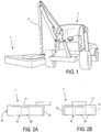
- Figure 1 schematically shows a trimming machine 1, mounted at the end of an arm 2 of a tractor 3.
- the arm 2 is a manipulation arm, with which the trimming machine can be lifted and with which the orientation of the trimming machine can be adapted to the orientation of a hedge surface to be trimmed.
- This manipulation can be controlled by an operator (not shown) in the tractor.
- the tractor drives along a hedge to be trimmed, and that the hedge face is trimmed while driving.
- the trimming machine 1 comprises revolving knife blocks, which are driven by motors.
- the actuation and supply of these motors is taken care of from the tractor 3 through conduits guided along the arm 2, which is however not shown for sake of simplicity.
- the trimming machine 1 at least in the example shown, has a general appearance of a rectangular box. However, the precise external appearance is not essential.
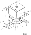
- FIG 2A shows a schematic side view of the trimming machine 1
- figure 2B shows a schematic front view thereof.
- the trimming machine 1 comprises a house 10, with a closed upper wall 11, a closed rear wall 12, and closed side walls 13, 14.
- a bottom face 15 of the trimming machine 1 is defined by the lower edges of the rear wall 12 and the side walls 13, 14 lying in one plane; this lower face is substantially open.
- a front face 16 of the trimming machine 1 is defined by the front edges of the upper wall 11 and the side walls 13, 14; this front face is substantially open.
- the trimming machine 1 is moved over a surface to be trimmed, with its lower face 15 directed towards this surface to be trimmed, and with its front face in the direction of movement, so that shoots of the hedge to be trimmed can enter the house 10.
- the trimming machine 1 is shown with its lower face 15 directed downwards for trimming an upper surface of a hedge, and with its front face 16 directed to the left for a movement to the left.
- mutually perpendicular directions x H , y H en z H will be defined, related to the surface of a hedge to be trimmed.
- the z H -direction is perpendicular to the surface to be trimmed, and will also be indicated as "height”.
- the x H -direction is parallel to the surface to be trimmed, in the main movement direction, and will also be indicated as "length”.
- the y H -direction is parallel to the surface to be trimmed, perpendicular to the main movement direction, and will also be indicated as "width" of "transverse direction”.
- Multiple rotating knife blocks 20 are arranged in the house 10. These are sketched only schematically with dotted lines in figure 2A and 2B , wherein figure 2B shows that there are multiple knife blocks 20 arranged next to each other in the transverse direction, in the example shown three. Although this is a preferred number, the present invention is not restricted to this number.
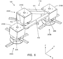
- FIG 3 is a schematic perspective view showing more details of a single knife block 20.
- the knife block 20 comprises a cylindrical knife carrier 21.
- a flange 22 is attached to the knife carrier 21.
- a knife 23 is attached to the flange 22.
- the knife carrier 21 is rotatebly attached to a drive unit 50; the rotation access is indicated at 24.
- the drive unit 50 is fixedly attached to a frame (not shown here) of the trimming machine 1.
- the rotation axes 24 is directed substantially vertically, i.e. substantially perpendicular to the bottom face 15.
- the knife 23 extends substantially radially with respect to the rotation axes 24. That is to say that the knife 23 has longitudinal cutting edges 23A, 23B which extend in a common plane perpendicular to the rotation axes 24. A center line of the knife is directed perpendicular to the rotation axes 24, and the cutting edges 23A, 23B are parallel to this center line.
- the knife 23 may be fixes with respect to the flange 22, but it is also possible, and even preferred, that the knife 23 is hingedly attached to the flange 22, by means of a hinge 26 of which the hinge axes is substantially parallel to the rotation axes 24.
- the knife hinges with respect to the flange 22, as indicated by arrows for instance when the knife meets a thick branch, thus counteracting damage and/or wear of the mechanism. Otherwise, the knife is directed to its normal operative position discussed above and illustrated in the figure, caused by the centrifugal force.
- the rotating knife block 20 vibrates as less as possible. Therefore, it is recommended to assure that the center of gravity of the rotating knife block coincides with the rotation axes 24. This may be achieved by counter weights, so that it is possible that the flange 22 only carries one single knife 23. However, it is preferred that the flange 22 carriers two knives 23, at a mutual angular distance of 180°, as shown, or that the flange 22 carries three knives 23, at a mutual angular distance of 120° (not shown). Four or more knives is also possible, wherein always the mutual angular distance is preferable approximately equal to 360°/N, with N the number of knives. The knives are located in a common plane. The knives attached to one and the same flange are commonly indicated as a knife disc 25. With this, it is also expressed that in an alternative embodiment the knives and the flange are formed as an integral whole.
- At least two flanges are attached to the knife carrier 21, at an axial distance from each other; this distance is in the order of about 7-8 cm in a suitable embodiment, but this is not critical.
- a second flange is indicated at 32.
- knives 33 are attached to the second flange 32; the knife disc defined hereby is indicated by reference numeral 35.
- the number of flanges is equal to two, but this number may also be larger.
- the knife disc 25 will be indicated as lower knife disc and the knife disc 26 will be indicated as upper knife disc.
- each flange 22, 32 carries two knives 23, 33.
- the number of knives of the second flange 32 is not necessarily equal to the number of knives of the first flange 22.
- the numbers of knives are mutually equal to each other, it is possible that the knives of the different flanges are mutually aligned with each other, or that the knives of the different flanges are displaces with respect to each other in circumferential direction over a distance of 180°/N, as in the embodiment shown.
- the trimming machine 1 also behaves as chopper for reducing the trimming waste. Consequently, this trimming waste does not have to be collected and/or disposed of and transported away: the reduced trimming waste eventually falls on the bottom below the hedge and will eventually turn into compost there.
- a single knife block 20 can only trim a track with a width corresponding to the diameter of a lowest knife disc, that is to say twice the distance from the rotation axes 24 to the free end of a knife 23; preferably this distance is the same for all knives.
- this diameter may be in the order of about 50 cm.
- hedges may typically have a height in the order of about 2 m. Therefore, it is desirable to be able to trim a wider track in one single work stroke.
- FIG. 4A-4D illustrate some variations of such arrangement, and problems associated with these variations will be discusses in the following, wherein it is noted that the arrangements according to figures 4A-4D are not the arrangement according to the invention.
- FIG 4A shows a schematic top view of an arrangement with three knife blocks, wherein for sake of simplicity only the three lowest knife discs 25 are shown, mutually distinguished from each other by addition of a letter A, B, C. It is assumed that the three knife blocks are mutually identical (this is preferred from cost considerations, but as such is not essential for the present invention).
- the three knife blocks are arranged in line, with which is mend that their three respective rotation axes 24A, 24B, 24C are located in a common vertical plane.
- the trimming machine 1 is moved in a direction perpendicular to that plane, indicated by an arrow W.
- the mutual distance between two neighboring knife blocks is always larger than the diameter of the knife discs 25. It will be clear that strips X remain between the knife blocks, that are not trimmed by the knife blocks. For a full trimming, the trimming machine 1 must be moved twice over the same work range.
- Figure 4B is a top view comparable to figure 4A of a variation where this disadvantage has been overcome because the mutual distance between two neighboring knife blocks is always smaller than the diameter of the knife discs 25. It will be clear that now there is the danger that the knives 23 of neighboring knife blocks touch each other.
- Figure 4C is a schematic front view of the three knife blocks 20A, 20B, 20C, illustrating that the problem of knives touching each other can be solved by shifting the middle knife block 20B axially (i.e. vertically) with respect to its neighbors, or at least shifting the knife discs 25B, 35B of the middle knife block 20B axially with respect to the neighboring knife discs 25A, 25C and 35A, 35C.
- this solution has the disadvantage that this leads to trim tracks of mutual different height, and thus it does not lead to a nice smooth trimming result.
- Figure 4D is a top view comparable to figure 4B illustrating that the mutual distance between two neighboring knife blocks can be smaller than the diameter of the knife discs 25 with the knives at the same height without the knives touching each other, if the orientations of the knives of the neighboring knife blocks are shifted over 180°/N.
- the extend to which overlap of two knife discs is possible is larger as N is smaller, and at equal N it is larger if neighboring knife blocks always have mutually opposite directions of rotation.
- a disadvantage is then always that the rotations of the different knife blocks must be mutually exactly synchronized, which leads to the necessity of a more complex and more expensive arrangement with for instance a toothed coupling belt or coupling chain.
- the present invention in contrast provides an arrangement in which such synchronization is not necessary.
- FIG. 5 schematically illustrates a further problem of a rotating trimming disc not according to the invention.
- a hedge to be trimmed is schematically indicated at H.
- the knife disc 25 When the lower knife disc 25 is held exactly parallel to the surface to be trimmed and the direction W of propagation is thus precisely perpendicular to the rotation axes 25, the knife disc 25 will at its front side (the right hand side in the figure) always cut the shoots U, but the entire knife disc 25 "rubs" so to say over the cut ends of the shoots U, which leads to rough ends.
- the present invention provides an arrangement with which this problem is solved as well.
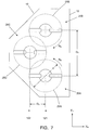
- FIG. 6 is a schematic perspective view of a trimming assembly 100 of a trimming machine according to the present invention, which trimming assembly 100 is arrangement within the housing 10, which is not shown in this figure for sake of simplicity.
- the trimming assembly 100 comprises multiple trimming units 200.
- Each trimming unit 200 comprises a knife block 20 as described in the above, as well as an associated drive motor 210.
- the different drive motors may rotate independently from each other. It is noted that within the context of the present invention is it also possible that the different drive motors are synchronized with each other, or that a single common drive motor is provided, but it is an advantage of the present invention that it is possible to implement the drive without the necessity of synchronization.
- the trimming assembly 100 comprises a frame 110 to which the different trimming units 200 are attached, so that the different trimming units 200 with respect to each other are positionally fixed. Alternatively, it would be possible that the trimming units are attached to the housing.
- the different trimming units may be mutually identical.
- the trimming units in general will be indicated by the reference numeral 200; in case it is desired to distinguish the trimming units with respect to each other, a letter A, B, C et cetera will be added, and this also applies to the constituting components.
- the trimming assembly 100 comprises three knife blocks 20A, 20B, 20C, arranged in a triangular configuration.
- Figure 7 shows thereof a schematic bottom view, in which the housing 10 is also shown.
- the entry 16 of the housing 10 is directed to the right in this figure.
- the trimming assembly 100 comprises an odd number of knife blocks 20, arranged in two mutually parallel rows in the y H -direction, wherein the rows in the x H -direction have a mutual distance larger than zero.
- the row closest to the entrance 16 will be indicated as front row 121, and the other row will be indicated as rear row 122.
- the number of knife blocks in the front row 121 may be equal to the number of knife blocks in the rear row 122 but is preferably one more than the number of knife blocks in the rear row 122.
- the knife blocks of the rear row 122 are displaced in the y H -direction with respect to the knife blocks of the front row 121, so that, seen according to the x H -direction, each knife block of the rear row 122 is always located between two knife blocks of the front row 121.
- the front row 121 and the rear row 122 mutually switch places, so that the rear row has more knife blocks than the front row.
- the front row 121 has two knife blocks 20A, 20B and the rear row 122 has a single knife block 20C.
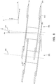
- Figure 8 is a schematic side view of the trimming assembly 100, in which only the knife blocks 20A and 20C are shown (knife block 20B is not visible because this is located behind knife block 20A).
- the plane of drawing is perpendicular to the y H -direction, and thus is an x H z H -plane.
- the entrance 16 of the housing 10 not shown for sake of simplicity is located at the right hand side in this view. It is shown in this figure that the rotation axes 24 of the knife blocks 20 make a small angle Z H -axes, in such a way that the lower knife disc 25 achieves its lowest point at the front side of this knife disc.
- an orthogonal system of axes x H , y H , z H has been defined in relation to the fixed world.
- the oblique position of the rotation axes 24 can be achieved by pivoting a rotation axes 24 around the y H -direction, starting from an orientation parallel to the height axes z H .
- an orthogonal system of axes x, y, z will be defined in relation to the trimming assembly 100.
- the z-axes will be defined parallel to the rotation axes 24.
- the z-axes makes an angle ⁇ with the direction z H .
- the z-direction will also be indicated as axial direction.
- the y-axes will be defined parallel to the y H -direction, and will thus also be indicated as width direction.
- the x-axes will be defined in the plane of a knife disc, perpendicular to the y- and z-directions. Thus, the x-axes makes an angle ⁇ with the direction x H .
- the plane of drawing of figure 8 is an xz-plane, perpendicular to the y-direction.
- An advantage of the oblique position of the trimming assembly 100 is that the upper knife disc 35 will arrive at the shoot to be trimmed and will cut this shoot before the lower knife disc 25 does so. This contributes to an improved chopping result.
- a further advantage of the oblique position of the trimming assembly 100 is that, after a shoot has been cut by the front edge of the lower knife disc 25, the lower knife disc will not rub over the tops of the remaining branches so that the disadvantages discussed with reference to figure 5 are avoided.
- Figure 8 further illustrates that the axial position of the knife block 20C of the rear row 122 is lower than the axial position of the two knife blocks 20A, 20B of the front row 121.
- the axial displacement dz of the rear row 122 with respect to the front row 121 is such that the lowest point of the lower knife disc 25A, 25B of the front knife blocks 20A, 20B is located at the same height as the lowest point of the lowest knife disc 25C of the rear knife block 20C, so that the disadvantage discussed with reference to figure 4C is avoided.
- This plane is indicated by reference numeral 800 is figure 8 .
- This imaginary plane has a fixed orientation with respect to the trimming unit 100.
- the trimming unit 100 is held in such a way that this imaginary common tangent plane 800 is held parallel to the surface to be trimmed.
- the trimming machine 1 is provided with a house 10 around the trimming unit 100, this house has a lower side parallel to the imaginary common tangent plane 800.
- Figure 7 shows that, because of the oblique position of the knife blocks 20A, 20B, 20C, it is possible that the mutual distance dx between the two knife blocks 20A, 20B of the front row 121 on the one hand and the knife block 20C of the rear row 122 on the other hand (measured in the x-direction between the plane in which the respective rotation axes 24A and 24B are located on the one hand and the plane parallel to that and through the rotation axes 24C on the other hand) can be fairly small, smaller than d ⁇ 2. Because of this, the knife discs can overlap each other in z-projection (compare figure 7 ) fairly far, which contributes to a good chopping result.
- the rotation directions of the front knife blocks 20A, 20B are mutually opposite, in such a way that the respective knives at their front edges move towards each other and then backwards in the central part of the housing 10, towards the rear knife block 20C, as illustrated by arrows RA and RB in figure 7 . Because of this, the twines cut by the front knives are guided to the rear knife, which contributes to an advantageous chopping result and reduces branch parts spatting outwards.
- the housing 10 already mentioned serves this purpose, on the one hand counteracting that a body part of a person can easily find itself between the rotating knifes, and on the other hand counteracting wood chips to shoot away as projectiles. Therefore, the housing 10 is almost completely closed, obviously having an open bottom face, as mentioned already in the above. On the other hand, it must be possible for the shoots to be cut to enter the housing, for which purpose it is known in practice that the front face of the housing is open, as also already mentioned in the above. However, this open front face intrinsically reduces the safety aspect.
- the present invention also aims to provide an improvement in this respect.
- Figure 10 shows a schematic cross section of a part of the trimming machine 1 in which a front knife block 20 is visible, and in which a part of the housing 10 is visible.
- the front side of the machine 1 is at the right hand side in the figure.
- a side wall 13 of the housing 10 is also visible, as well as the upper wall 11.
- the housing 10 has a closed front wall 16 at a fairly large distance D16 with respect to the front edge of the knives of the front knife block 20.
- This distance D16 is at least 15 cm, preferably even more than 20 cm, and most preferably in the order of 25 cm.
- the height dimension of the front wall 16, and thus the height H of the front wall 11, is also at least 15 cm, preferably even more than 20 cm, and most preferably in the order of 25 cm. It is preferred that H is equal to D16.
- the position of the lower edge 116 of the front wall 16 plays a roll.
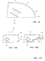
- the front wall 16 is vertical, and makes an angle of 90° with the upper wall 11, but it is also possible that the front wall 16 is bend according to a quarter cylindrical contour and thus smoothly changes into the upper wall 11, as schematically shown in figure 12 .
- the front wall 16 may be a rigid wall.
- the front wall 16 is formed by sturdy but flexible rubber or plastic strips 117, of which the upper end 118 is attached to the front edge 111 of the upper wall 11, as illustrated in figure 13A .
- the strips may have a width of about 5 to 10 cm, although other sizes are also conceivable. Such strips will bend along inwards to facilitate a shoot to be cut to enter the housing 10 as illustrated in figure 13B , which contributes to a good cutting result.
- a trimming machine 1 comprising a housing 10 and three trimming units 200A, 200B, 200C, arranged in the housing according to a triangular configuration.
- Each trimming unit comprises a rotatable knife block 20; the different knife blocks have mutually parallel rotation axes 24.
- the housing has an open bottom face 15 perpendicular to a z H -direction.
- the housing has a front side. A direction directed toward the front side and parallel to the bottom face defines an x H -direction. A direction directed perpendicular to the x H -direction and parallel to the bottom face defines an y H -direction.
- Each rotation axes is located in an x H -z H -plane and makes a small angle ⁇ larger than zero with the z-direction.
- the third trimming unit 200C is displaced in x H -direction and in y H -direction with respect to the two first mentioned trimming units 200A, 200B but is located at the same height in z H -direction as the two first mentioned trimming units 200A, 200B.
Landscapes
- Life Sciences & Earth Sciences (AREA)
- Environmental Sciences (AREA)
- Biodiversity & Conservation Biology (AREA)
- Ecology (AREA)
- Forests & Forestry (AREA)
- Nonmetal Cutting Devices (AREA)
- Crushing And Pulverization Processes (AREA)
- Harvester Elements (AREA)
Priority Applications (1)
| Application Number | Priority Date | Filing Date | Title |
|---|---|---|---|
| PL09747931T PL2346314T3 (pl) | 2008-10-22 | 2009-10-22 | Urządzenie przycinające |
Applications Claiming Priority (2)
| Application Number | Priority Date | Filing Date | Title |
|---|---|---|---|
| NL1036097A NL1036097C (nl) | 2008-10-22 | 2008-10-22 | Snoeimachine. |
| PCT/NL2009/000201 WO2010053351A1 (en) | 2008-10-22 | 2009-10-22 | Trimming machine |
Publications (2)
| Publication Number | Publication Date |
|---|---|
| EP2346314A1 EP2346314A1 (en) | 2011-07-27 |
| EP2346314B1 true EP2346314B1 (en) | 2020-01-22 |
Family
ID=40691343
Family Applications (1)
| Application Number | Title | Priority Date | Filing Date |
|---|---|---|---|
| EP09747931.5A Active EP2346314B1 (en) | 2008-10-22 | 2009-10-22 | Trimming machine |
Country Status (6)
| Country | Link |
|---|---|
| EP (1) | EP2346314B1 (da) |
| DE (1) | DE202009019153U1 (da) |
| DK (1) | DK2346314T3 (da) |
| NL (1) | NL1036097C (da) |
| PL (1) | PL2346314T3 (da) |
| WO (1) | WO2010053351A1 (da) |
Families Citing this family (7)
| Publication number | Priority date | Publication date | Assignee | Title |
|---|---|---|---|---|
| CN109661893A (zh) * | 2019-02-18 | 2019-04-23 | 江苏集萃道路工程技术与装备研究所有限公司 | 一种园林绿化车用三轴篱心刀 |
| CN110178570A (zh) * | 2019-06-28 | 2019-08-30 | 广州交投绿化建设有限公司 | 一种绿篱修剪装置总成 |
| CN110178571A (zh) * | 2019-06-28 | 2019-08-30 | 广州交投绿化建设有限公司 | 一种绿篱修剪机头 |
| CN111466218B (zh) * | 2020-05-22 | 2024-08-20 | 江苏赛欧智能科技有限公司 | 一种绿化综合养护车用绿篱机具离心剪 |
| FR3114000B1 (fr) * | 2020-09-11 | 2023-09-15 | Kirogn | Dispositif de lamier |
| CN112449900B (zh) * | 2020-11-25 | 2023-04-28 | 长沙中联重科环境产业有限公司 | 绿篱修剪刀盘及绿篱修剪作业车 |
| CN112449901B (zh) * | 2020-11-25 | 2023-12-15 | 长沙中联重科环境产业有限公司 | 绿篱修剪刀盘 |
Citations (1)
| Publication number | Priority date | Publication date | Assignee | Title |
|---|---|---|---|---|
| GB2246695A (en) * | 1990-08-10 | 1992-02-12 | Honda Motor Co Ltd | Cutter and housing assembly for lawn mower |
Family Cites Families (7)
| Publication number | Priority date | Publication date | Assignee | Title |
|---|---|---|---|---|
| US26793A (en) * | 1860-01-10 | Drain-tile machine | ||
| GB1143812A (da) | 1965-05-10 | |||
| US4302922A (en) * | 1980-07-07 | 1981-12-01 | Orange Enterprises, Inc. | Pruning boom |
| DE4240866B4 (de) * | 1992-12-04 | 2005-04-21 | Armin Pieroth | Vorrichtung zum Schneiden von Hecken |
| DE4418762A1 (de) * | 1994-05-28 | 1995-11-30 | Armin Pieroth | Vorrichtung zum Schneiden von Hecken |
| US5430999A (en) * | 1994-09-01 | 1995-07-11 | Grant; Spencer A. | Tree trimming and pruning machine |
| CA2493348C (en) * | 2005-01-19 | 2009-10-27 | Barry D. Fenton | Rotating cylindrical flailing vegetation cutter |
-
2008
- 2008-10-22 NL NL1036097A patent/NL1036097C/nl not_active IP Right Cessation
-
2009
- 2009-10-22 DK DK09747931.5T patent/DK2346314T3/da active
- 2009-10-22 WO PCT/NL2009/000201 patent/WO2010053351A1/en not_active Ceased
- 2009-10-22 PL PL09747931T patent/PL2346314T3/pl unknown
- 2009-10-22 DE DE202009019153.2U patent/DE202009019153U1/de not_active Expired - Lifetime
- 2009-10-22 EP EP09747931.5A patent/EP2346314B1/en active Active
Patent Citations (1)
| Publication number | Priority date | Publication date | Assignee | Title |
|---|---|---|---|---|
| GB2246695A (en) * | 1990-08-10 | 1992-02-12 | Honda Motor Co Ltd | Cutter and housing assembly for lawn mower |
Also Published As
| Publication number | Publication date |
|---|---|
| DE202009019153U1 (de) | 2017-04-04 |
| DK2346314T3 (da) | 2020-03-30 |
| WO2010053351A1 (en) | 2010-05-14 |
| EP2346314A1 (en) | 2011-07-27 |
| PL2346314T3 (pl) | 2020-07-13 |
| NL1036097C (nl) | 2010-04-23 |
Similar Documents
| Publication | Publication Date | Title |
|---|---|---|
| EP2346314A1 (en) | Trimming machine | |
| EP3549429B1 (en) | Lawn mower robot | |
| CA2818613C (en) | Attachment device for harvesting stalky stem material | |
| EP3597024A1 (en) | High-efficiency cutting system | |
| EP2713695B1 (en) | Cam driven low profile sickle drive | |
| US4730445A (en) | Rotary mower | |
| US4304088A (en) | Rotary mower with end-to-end connected blade-carrier supports | |
| US11123892B2 (en) | Frame for a cutting machine | |
| JP6709149B2 (ja) | サトウキビ収穫機 | |
| EP1541009B1 (en) | A multi-blade pruning machine for pruning espalier vineyards | |
| KR100967236B1 (ko) | 버섯 다듬 장치 | |
| EP4233518A1 (en) | Garden tool with blade cover | |
| KR200303974Y1 (ko) | 육류칼집 형성기 | |
| HU216487B (hu) | Arató-cséplő gép | |
| KR200354640Y1 (ko) | 생선뼈와 생선살 분리장치 | |
| KR20030004958A (ko) | 육류 칼집 자동성형기 | |
| KR20210059875A (ko) | 회전식 세절기 | |
| CZ281117B6 (cs) | Žací, případně řezací stroj | |
| EP2708106B1 (en) | An agricultural mower | |
| KR200301355Y1 (ko) | 유부 자동절단기 | |
| DE60104370D1 (de) | Motorrasenmäher mit Drehantriebsvorrichtung für einen Schneidmesser | |
| JP6879510B2 (ja) | 根の切断支持体を備えた作物調製機 | |
| JP6912775B2 (ja) | 葉除去機構を備えた作物調製機 | |
| JP6831518B2 (ja) | ブレードを備えた作物調製機 | |
| CN122056168A (zh) | 割草机 |
Legal Events
| Date | Code | Title | Description |
|---|---|---|---|
| PUAI | Public reference made under article 153(3) epc to a published international application that has entered the european phase |
Free format text: ORIGINAL CODE: 0009012 |
|
| 17P | Request for examination filed |
Effective date: 20110511 |
|
| AK | Designated contracting states |
Kind code of ref document: A1 Designated state(s): AT BE BG CH CY CZ DE DK EE ES FI FR GB GR HR HU IE IS IT LI LT LU LV MC MK MT NL NO PL PT RO SE SI SK SM TR |
|
| AX | Request for extension of the european patent |
Extension state: AL BA RS |
|
| DAX | Request for extension of the european patent (deleted) | ||
| STAA | Information on the status of an ep patent application or granted ep patent |
Free format text: STATUS: EXAMINATION IS IN PROGRESS |
|
| 17Q | First examination report despatched |
Effective date: 20171221 |
|
| RIN1 | Information on inventor provided before grant (corrected) |
Inventor name: HOMMEN, ERWIN ANDREAS GERARDUS |
|
| TPAC | Observations filed by third parties |
Free format text: ORIGINAL CODE: EPIDOSNTIPA |
|
| GRAP | Despatch of communication of intention to grant a patent |
Free format text: ORIGINAL CODE: EPIDOSNIGR1 |
|
| STAA | Information on the status of an ep patent application or granted ep patent |
Free format text: STATUS: GRANT OF PATENT IS INTENDED |
|
| INTG | Intention to grant announced |
Effective date: 20190725 |
|
| GRAS | Grant fee paid |
Free format text: ORIGINAL CODE: EPIDOSNIGR3 |
|
| GRAA | (expected) grant |
Free format text: ORIGINAL CODE: 0009210 |
|
| STAA | Information on the status of an ep patent application or granted ep patent |
Free format text: STATUS: THE PATENT HAS BEEN GRANTED |
|
| AK | Designated contracting states |
Kind code of ref document: B1 Designated state(s): AT BE BG CH CY CZ DE DK EE ES FI FR GB GR HR HU IE IS IT LI LT LU LV MC MK MT NL NO PL PT RO SE SI SK SM TR |
|
| RAP1 | Party data changed (applicant data changed or rights of an application transferred) |
Owner name: BECX MACHINES B.V. |
|
| REG | Reference to a national code |
Ref country code: GB Ref legal event code: FG4D |
|
| REG | Reference to a national code |
Ref country code: CH Ref legal event code: EP |
|
| REG | Reference to a national code |
Ref country code: AT Ref legal event code: REF Ref document number: 1226330 Country of ref document: AT Kind code of ref document: T Effective date: 20200215 |
|
| REG | Reference to a national code |
Ref country code: IE Ref legal event code: FG4D |
|
| REG | Reference to a national code |
Ref country code: DE Ref legal event code: R096 Ref document number: 602009061057 Country of ref document: DE |
|
| REG | Reference to a national code |
Ref country code: DK Ref legal event code: T3 Effective date: 20200327 |
|
| REG | Reference to a national code |
Ref country code: SE Ref legal event code: TRGR |
|
| REG | Reference to a national code |
Ref country code: FI Ref legal event code: FGE |
|
| REG | Reference to a national code |
Ref country code: NL Ref legal event code: FP |
|
| REG | Reference to a national code |
Ref country code: LT Ref legal event code: MG4D |
|
| PG25 | Lapsed in a contracting state [announced via postgrant information from national office to epo] |
Ref country code: PT Free format text: LAPSE BECAUSE OF FAILURE TO SUBMIT A TRANSLATION OF THE DESCRIPTION OR TO PAY THE FEE WITHIN THE PRESCRIBED TIME-LIMIT Effective date: 20200614 Ref country code: NO Free format text: LAPSE BECAUSE OF FAILURE TO SUBMIT A TRANSLATION OF THE DESCRIPTION OR TO PAY THE FEE WITHIN THE PRESCRIBED TIME-LIMIT Effective date: 20200422 |
|
| PG25 | Lapsed in a contracting state [announced via postgrant information from national office to epo] |
Ref country code: LV Free format text: LAPSE BECAUSE OF FAILURE TO SUBMIT A TRANSLATION OF THE DESCRIPTION OR TO PAY THE FEE WITHIN THE PRESCRIBED TIME-LIMIT Effective date: 20200122 Ref country code: HR Free format text: LAPSE BECAUSE OF FAILURE TO SUBMIT A TRANSLATION OF THE DESCRIPTION OR TO PAY THE FEE WITHIN THE PRESCRIBED TIME-LIMIT Effective date: 20200122 Ref country code: GR Free format text: LAPSE BECAUSE OF FAILURE TO SUBMIT A TRANSLATION OF THE DESCRIPTION OR TO PAY THE FEE WITHIN THE PRESCRIBED TIME-LIMIT Effective date: 20200423 Ref country code: IS Free format text: LAPSE BECAUSE OF FAILURE TO SUBMIT A TRANSLATION OF THE DESCRIPTION OR TO PAY THE FEE WITHIN THE PRESCRIBED TIME-LIMIT Effective date: 20200522 Ref country code: BG Free format text: LAPSE BECAUSE OF FAILURE TO SUBMIT A TRANSLATION OF THE DESCRIPTION OR TO PAY THE FEE WITHIN THE PRESCRIBED TIME-LIMIT Effective date: 20200422 |
|
| REG | Reference to a national code |
Ref country code: DE Ref legal event code: R097 Ref document number: 602009061057 Country of ref document: DE |
|
| PG25 | Lapsed in a contracting state [announced via postgrant information from national office to epo] |
Ref country code: SM Free format text: LAPSE BECAUSE OF FAILURE TO SUBMIT A TRANSLATION OF THE DESCRIPTION OR TO PAY THE FEE WITHIN THE PRESCRIBED TIME-LIMIT Effective date: 20200122 Ref country code: EE Free format text: LAPSE BECAUSE OF FAILURE TO SUBMIT A TRANSLATION OF THE DESCRIPTION OR TO PAY THE FEE WITHIN THE PRESCRIBED TIME-LIMIT Effective date: 20200122 Ref country code: LT Free format text: LAPSE BECAUSE OF FAILURE TO SUBMIT A TRANSLATION OF THE DESCRIPTION OR TO PAY THE FEE WITHIN THE PRESCRIBED TIME-LIMIT Effective date: 20200122 Ref country code: RO Free format text: LAPSE BECAUSE OF FAILURE TO SUBMIT A TRANSLATION OF THE DESCRIPTION OR TO PAY THE FEE WITHIN THE PRESCRIBED TIME-LIMIT Effective date: 20200122 Ref country code: ES Free format text: LAPSE BECAUSE OF FAILURE TO SUBMIT A TRANSLATION OF THE DESCRIPTION OR TO PAY THE FEE WITHIN THE PRESCRIBED TIME-LIMIT Effective date: 20200122 Ref country code: SK Free format text: LAPSE BECAUSE OF FAILURE TO SUBMIT A TRANSLATION OF THE DESCRIPTION OR TO PAY THE FEE WITHIN THE PRESCRIBED TIME-LIMIT Effective date: 20200122 |
|
| PLBE | No opposition filed within time limit |
Free format text: ORIGINAL CODE: 0009261 |
|
| STAA | Information on the status of an ep patent application or granted ep patent |
Free format text: STATUS: NO OPPOSITION FILED WITHIN TIME LIMIT |
|
| 26N | No opposition filed |
Effective date: 20201023 |
|
| PG25 | Lapsed in a contracting state [announced via postgrant information from national office to epo] |
Ref country code: SI Free format text: LAPSE BECAUSE OF FAILURE TO SUBMIT A TRANSLATION OF THE DESCRIPTION OR TO PAY THE FEE WITHIN THE PRESCRIBED TIME-LIMIT Effective date: 20200122 |
|
| PG25 | Lapsed in a contracting state [announced via postgrant information from national office to epo] |
Ref country code: MC Free format text: LAPSE BECAUSE OF FAILURE TO SUBMIT A TRANSLATION OF THE DESCRIPTION OR TO PAY THE FEE WITHIN THE PRESCRIBED TIME-LIMIT Effective date: 20200122 |
|
| REG | Reference to a national code |
Ref country code: AT Ref legal event code: UEP Ref document number: 1226330 Country of ref document: AT Kind code of ref document: T Effective date: 20200122 |
|
| PG25 | Lapsed in a contracting state [announced via postgrant information from national office to epo] |
Ref country code: TR Free format text: LAPSE BECAUSE OF FAILURE TO SUBMIT A TRANSLATION OF THE DESCRIPTION OR TO PAY THE FEE WITHIN THE PRESCRIBED TIME-LIMIT Effective date: 20200122 Ref country code: MT Free format text: LAPSE BECAUSE OF FAILURE TO SUBMIT A TRANSLATION OF THE DESCRIPTION OR TO PAY THE FEE WITHIN THE PRESCRIBED TIME-LIMIT Effective date: 20200122 Ref country code: CY Free format text: LAPSE BECAUSE OF FAILURE TO SUBMIT A TRANSLATION OF THE DESCRIPTION OR TO PAY THE FEE WITHIN THE PRESCRIBED TIME-LIMIT Effective date: 20200122 |
|
| PG25 | Lapsed in a contracting state [announced via postgrant information from national office to epo] |
Ref country code: MK Free format text: LAPSE BECAUSE OF FAILURE TO SUBMIT A TRANSLATION OF THE DESCRIPTION OR TO PAY THE FEE WITHIN THE PRESCRIBED TIME-LIMIT Effective date: 20200122 |
|
| P01 | Opt-out of the competence of the unified patent court (upc) registered |
Free format text: CASE NUMBER: APP_36454/2024 Effective date: 20240618 |
|
| REG | Reference to a national code |
Ref country code: CH Ref legal event code: U11 Free format text: ST27 STATUS EVENT CODE: U-0-0-U10-U11 (AS PROVIDED BY THE NATIONAL OFFICE) Effective date: 20251101 |
|
| PGFP | Annual fee paid to national office [announced via postgrant information from national office to epo] |
Ref country code: LU Payment date: 20251022 Year of fee payment: 17 Ref country code: NL Payment date: 20251021 Year of fee payment: 17 |
|
| PGFP | Annual fee paid to national office [announced via postgrant information from national office to epo] |
Ref country code: DE Payment date: 20251022 Year of fee payment: 17 |
|
| PGFP | Annual fee paid to national office [announced via postgrant information from national office to epo] |
Ref country code: GB Payment date: 20251022 Year of fee payment: 17 |
|
| PGFP | Annual fee paid to national office [announced via postgrant information from national office to epo] |
Ref country code: AT Payment date: 20251022 Year of fee payment: 17 |
|
| PGFP | Annual fee paid to national office [announced via postgrant information from national office to epo] |
Ref country code: FI Payment date: 20251028 Year of fee payment: 17 Ref country code: DK Payment date: 20251027 Year of fee payment: 17 Ref country code: IT Payment date: 20251024 Year of fee payment: 17 |
|
| PGFP | Annual fee paid to national office [announced via postgrant information from national office to epo] |
Ref country code: FR Payment date: 20251029 Year of fee payment: 17 |
|
| PGFP | Annual fee paid to national office [announced via postgrant information from national office to epo] |
Ref country code: BE Payment date: 20251021 Year of fee payment: 17 |
|
| PGFP | Annual fee paid to national office [announced via postgrant information from national office to epo] |
Ref country code: CH Payment date: 20251101 Year of fee payment: 17 Ref country code: SE Payment date: 20251021 Year of fee payment: 17 |
|
| PGFP | Annual fee paid to national office [announced via postgrant information from national office to epo] |
Ref country code: IE Payment date: 20251024 Year of fee payment: 17 Ref country code: CZ Payment date: 20251015 Year of fee payment: 17 |
|
| PGFP | Annual fee paid to national office [announced via postgrant information from national office to epo] |
Ref country code: PL Payment date: 20251010 Year of fee payment: 17 |