EP2346546B1 - Drainageanordnung für körperflüssigkeiten - Google Patents
Drainageanordnung für körperflüssigkeiten Download PDFInfo
- Publication number
- EP2346546B1 EP2346546B1 EP09821003.2A EP09821003A EP2346546B1 EP 2346546 B1 EP2346546 B1 EP 2346546B1 EP 09821003 A EP09821003 A EP 09821003A EP 2346546 B1 EP2346546 B1 EP 2346546B1
- Authority
- EP
- European Patent Office
- Prior art keywords
- fluid
- cover
- bag
- volume
- assembly
- Prior art date
- Legal status (The legal status is an assumption and is not a legal conclusion. Google has not performed a legal analysis and makes no representation as to the accuracy of the status listed.)
- Active
Links
Images






Classifications
-
- A—HUMAN NECESSITIES
- A61—MEDICAL OR VETERINARY SCIENCE; HYGIENE
- A61F—FILTERS IMPLANTABLE INTO BLOOD VESSELS; PROSTHESES; DEVICES PROVIDING PATENCY TO, OR PREVENTING COLLAPSING OF, TUBULAR STRUCTURES OF THE BODY, e.g. STENTS; ORTHOPAEDIC, NURSING OR CONTRACEPTIVE DEVICES; FOMENTATION; TREATMENT OR PROTECTION OF EYES OR EARS; BANDAGES, DRESSINGS OR ABSORBENT PADS; FIRST-AID KITS
- A61F5/00—Orthopaedic methods or devices for non-surgical treatment of bones or joints; Nursing devices ; Anti-rape devices
- A61F5/44—Devices worn by the patient for reception of urine, faeces, catamenial or other discharge; Colostomy devices
-
- A—HUMAN NECESSITIES
- A61—MEDICAL OR VETERINARY SCIENCE; HYGIENE
- A61J—CONTAINERS SPECIALLY ADAPTED FOR MEDICAL OR PHARMACEUTICAL PURPOSES; DEVICES OR METHODS SPECIALLY ADAPTED FOR BRINGING PHARMACEUTICAL PRODUCTS INTO PARTICULAR PHYSICAL OR ADMINISTERING FORMS; DEVICES FOR ADMINISTERING FOOD OR MEDICINES ORALLY; BABY COMFORTERS; DEVICES FOR RECEIVING SPITTLE
- A61J1/00—Containers specially adapted for medical or pharmaceutical purposes
- A61J1/05—Containers specially adapted for medical or pharmaceutical purposes for collecting, storing or administering blood, plasma or medical fluids ; Infusion or perfusion containers
- A61J1/10—Bag-type containers
-
- A—HUMAN NECESSITIES
- A61—MEDICAL OR VETERINARY SCIENCE; HYGIENE
- A61J—CONTAINERS SPECIALLY ADAPTED FOR MEDICAL OR PHARMACEUTICAL PURPOSES; DEVICES OR METHODS SPECIALLY ADAPTED FOR BRINGING PHARMACEUTICAL PRODUCTS INTO PARTICULAR PHYSICAL OR ADMINISTERING FORMS; DEVICES FOR ADMINISTERING FOOD OR MEDICINES ORALLY; BABY COMFORTERS; DEVICES FOR RECEIVING SPITTLE
- A61J1/00—Containers specially adapted for medical or pharmaceutical purposes
- A61J1/14—Details; Accessories therefor
- A61J1/1462—Containers with provisions for hanging, e.g. integral adaptations of the container
-
- A—HUMAN NECESSITIES
- A61—MEDICAL OR VETERINARY SCIENCE; HYGIENE
- A61J—CONTAINERS SPECIALLY ADAPTED FOR MEDICAL OR PHARMACEUTICAL PURPOSES; DEVICES OR METHODS SPECIALLY ADAPTED FOR BRINGING PHARMACEUTICAL PRODUCTS INTO PARTICULAR PHYSICAL OR ADMINISTERING FORMS; DEVICES FOR ADMINISTERING FOOD OR MEDICINES ORALLY; BABY COMFORTERS; DEVICES FOR RECEIVING SPITTLE
- A61J1/00—Containers specially adapted for medical or pharmaceutical purposes
- A61J1/14—Details; Accessories therefor
- A61J1/1475—Inlet or outlet ports
- A61J1/1487—Inlet or outlet ports with friction fit, e.g. connecting tubes directly to a protruding port
-
- A—HUMAN NECESSITIES
- A61—MEDICAL OR VETERINARY SCIENCE; HYGIENE
- A61J—CONTAINERS SPECIALLY ADAPTED FOR MEDICAL OR PHARMACEUTICAL PURPOSES; DEVICES OR METHODS SPECIALLY ADAPTED FOR BRINGING PHARMACEUTICAL PRODUCTS INTO PARTICULAR PHYSICAL OR ADMINISTERING FORMS; DEVICES FOR ADMINISTERING FOOD OR MEDICINES ORALLY; BABY COMFORTERS; DEVICES FOR RECEIVING SPITTLE
- A61J1/00—Containers specially adapted for medical or pharmaceutical purposes
- A61J1/14—Details; Accessories therefor
- A61J1/20—Arrangements for transferring or mixing fluids, e.g. from vial to syringe
- A61J1/22—Arrangements for transferring or mixing fluids, e.g. from vial to syringe with means for metering the amount of fluid
-
- A—HUMAN NECESSITIES
- A61—MEDICAL OR VETERINARY SCIENCE; HYGIENE
- A61M—DEVICES FOR INTRODUCING MEDIA INTO, OR ONTO, THE BODY; DEVICES FOR TRANSDUCING BODY MEDIA OR FOR TAKING MEDIA FROM THE BODY; DEVICES FOR PRODUCING OR ENDING SLEEP OR STUPOR
- A61M1/00—Suction or pumping devices for medical purposes; Devices for carrying-off, for treatment of, or for carrying-over, body-liquids; Drainage systems
- A61M1/69—Drainage containers not being adapted for subjection to vacuum, e.g. bags
-
- A—HUMAN NECESSITIES
- A61—MEDICAL OR VETERINARY SCIENCE; HYGIENE
- A61J—CONTAINERS SPECIALLY ADAPTED FOR MEDICAL OR PHARMACEUTICAL PURPOSES; DEVICES OR METHODS SPECIALLY ADAPTED FOR BRINGING PHARMACEUTICAL PRODUCTS INTO PARTICULAR PHYSICAL OR ADMINISTERING FORMS; DEVICES FOR ADMINISTERING FOOD OR MEDICINES ORALLY; BABY COMFORTERS; DEVICES FOR RECEIVING SPITTLE
- A61J1/00—Containers specially adapted for medical or pharmaceutical purposes
- A61J1/14—Details; Accessories therefor
- A61J1/1468—Containers characterised by specific material properties
-
- A—HUMAN NECESSITIES
- A61—MEDICAL OR VETERINARY SCIENCE; HYGIENE
- A61M—DEVICES FOR INTRODUCING MEDIA INTO, OR ONTO, THE BODY; DEVICES FOR TRANSDUCING BODY MEDIA OR FOR TAKING MEDIA FROM THE BODY; DEVICES FOR PRODUCING OR ENDING SLEEP OR STUPOR
- A61M2205/00—General characteristics of the apparatus
- A61M2205/58—Means for facilitating use, e.g. by people with impaired vision
- A61M2205/583—Means for facilitating use, e.g. by people with impaired vision by visual feedback
-
- Y—GENERAL TAGGING OF NEW TECHNOLOGICAL DEVELOPMENTS; GENERAL TAGGING OF CROSS-SECTIONAL TECHNOLOGIES SPANNING OVER SEVERAL SECTIONS OF THE IPC; TECHNICAL SUBJECTS COVERED BY FORMER USPC CROSS-REFERENCE ART COLLECTIONS [XRACs] AND DIGESTS
- Y10—TECHNICAL SUBJECTS COVERED BY FORMER USPC
- Y10T—TECHNICAL SUBJECTS COVERED BY FORMER US CLASSIFICATION
- Y10T156/00—Adhesive bonding and miscellaneous chemical manufacture
- Y10T156/10—Methods of surface bonding and/or assembly therefor
Definitions
- the present disclosure relates generally to the field of medical devices. More specifically, the present disclosure relates to a bodily fluid drainage assembly.
- US 4496354 A discloses an ostomy appliance comprising a body side member and receiving bag and a disposable receiving bag.
- US 4 874 387 A relates broadly to the art of body fluid drainage bags and tubing, and more specifically to the covers for these items.
- connection to refers to any form of interaction between two or more entities, including mechanical, electrical, magnetic, electromagnetic, fluid, and thermal interaction. Two components may be coupled to each other even though they are not in direct contact with each other.
- abutting refers to items that are in direct physical contact with each other, although the items may not necessarily be attached together.
- the present invention discloses a bodily fluid drainage assembly [1000], comprising: a fluid bag [1010]; and at least one cover [1030] characterised in that the cover is coupled to the fluid bag [1010] at a seam [1033] formed along a portion of a top side of the fluid bag [1010], wherein the cover [1030] is movable relative to the fluid bag [1010] between a covered orientation in which the cover [1030] and is configured to at least partially obscure observation of a fluid retained within the fluid bag [1010] and a viewing orientation in which a bottom end of the cover [1030] can be at least partially lifted such that the fluid bag [1010] can be directly viewed while a top end of the cover [1030] remains coupled to the fluid bag [1010], wherein the cover [1030] comprises a first volume indicator [1017] that permits viewing of a portion of the fluid bag [1010] through the cover [1030] such that an approximate volume of fluid within the fluid bag [1010] can be ascertained
- FIGS. 1-2 depict drainage bodily fluid drainage assembly 100, from a front elevation view, wherein FIG. 1 is an exploded-perspective view and FIG. 2 is a perspective view after the assembly has been assembled.
- Bodily fluid drainage assembly 100 may comprise a fluid bag 110, a first cover 130 and a second cover 140. Assembly 100 is configured to receive bodily fluid; optionally retain the fluid; at least partially obscure the visibility of the fluid while allowing an approximate volume of the fluid to be determined; and optionally allow the fluid to be directly viewed by at least partially removing a portion of the assembly.
- Drainage bag 110 and first and second covers 120 and 130 may comprise polyvinyl chloride, polyurethane, vinyl or any other suitable material known in the art.
- Drainage bag 110 may comprise one or more panels of a liquid impervious material, wherein at least a portion of the front panel 112 is substantially transparent or semitransparent such that a liquid contained within the bag may be readily observed.
- the panels may be joined along an outer edge 111 via radio frequency (RF) welding, heat sealing, gluing, or any other suitable technique. Once joined, the two panels comprise a seam 113 adjacent to outer edge 111. When coupled together, the panels form a fillable void that may receive fluid via an inlet tube 121 and a corresponding inlet aperture (not visible) that are located on upper portion 115 of bag 110. Approximate volume of fluid within the bag may be ascertained via a first volume indicator 117, which may comprise graduations marked on front panel 112 of bag 110.
- RF radio frequency
- graduations 117 denote various predetermined volumes and may be printed on the fluid bag.
- the graduations may comprise raised or recessed portions of the fluid bag that are formed during or after manufacturing of the fluid bag.
- the graduations may represent any predetermined measurement of volume, such as fluid ounces and/or Milliliters and may vary in their distribution accordingly. Additionally, the space between graduations may not be uniform within the scale to account for a non-linear rate of rise in fluid level to account for expansion of the fluid bag.
- graduations 117 are located on a right hand portion (as seen from the viewer's perspective) of fluid bag 110; however, in other embodiments, the graduations may be located anywhere on fluid bag 110. Since at least a portion of front panel 112 is transparent, the top of the fluid can be compared to the graduations and an approximate volume of the fluid can be determined.
- the fluid bag may be manufactured using a one-piece method, wherein the bag comprises a single piece of plastic that is folded along one or more edges.
- the shape and size of assembly 100 is for illustrative purposes only and may vary.
- a hanger 124 is located in a non-fillable portion of upper portion 115 and is configured to allow assembly 100 to be suspended from a patient, or a nearby structure such as a wheelchair, bed, or stand.
- Hanger 124 may comprise a hook-like extension, an aperture, or both.
- the hanger may comprise one or more pieces of plastic and may be coupled to assembly 100 via RF welding, heat sealing, gluing, hardware, or any other suitable technique.
- hanger 124 may be coupled to assembly 100 such that it may be removed.
- hanger 124 may comprise an aperture in bag 110 and/or first and second covers 130 and 140.
- An outlet tube 122 and corresponding drainage bag outlet aperture are located on a bottom portion 116 of the fluid bag.
- the outlet tube 122 may allow a fluid contained within bag 110 to be drained from the bag or retained within the bag via an output regulator 123.
- Output regulator 123 may comprise a plastic or metal clip, in-line valve, or any other suitable structure.
- Fluid bag 110 may further comprise an outlet tube holder 114 that comprises a slot, loop, or hook that is configured to receive and reversibly retain outlet tube 122 in an at least partially upright position.
- the size, shape, and proportions of the fluid bag may vary (See FIGS. 6-9 ).
- the size, shape, and proportions of the inlet and outlet tubes, as well as the materials from which the fluid bag and tubes are manufactured may vary.
- the hanger comprises a contiguous extension of the bag and in another embodiment, the hanger comprises an aperture in the bag.
- Bodily fluid drainage assembly 100 may further comprise first cover 130 that is an opaque material and which may comprise a similar shape as fluid drainage bag 110.
- First cover 130 has an outer edge 131 that may be at least partially aligned with outer edge 111 of fluid bag 110.
- a seam 133 may be formed along outer edge 111.
- the first cover may be coupled to the fluid drainage bag via RF welding, heat sealing, gluing, hardware, or any other suitable technique.
- Cover 130 may be coupled to bag 110 only along outer edge 131, or in another embodiment, the cover is coupled to the bag along more than one edge.
- Cover 130 further comprises perforations 134 that are located adjacent to seam 133 and are configured to allow cover 130 to be at least partially removed from bag 110.
- Cover 130 further comprises an interior edge 132 that may have a cutout 138 that partially surrounds the junction of inlet tube 121 and fluid bag 110.
- a second volume indicator 135 is located on first cover 130 and comprises a fluid level indicator 136 and graduations 137. The function of second volume indicator 135 is described in text associated with FIGS. 3A-3B , below.
- Second cover 140 may comprise an opaque material that may be identical to first cover 130.
- the second cover may comprise an outer edge 141, an inner edge 142, a seam 143, perforations 144, and a cutout 148.
- second cover 140 may be coupled to bag 110 along outer edge 141 to form seam 143.
- Perforations 144 may be formed in cover 140 along that seam such that the cover may be at least partially removed.
- First and second covers 130 and 140 may be coupled to fluid bag 110 during manufacture of the bag such that seams and 133 and/or 143 are formed at the same time.
- first and second covers may be used without deviating from the present disclosure.
- the first and second covers may or may not be coupled to the lower portion of the fluid bag and the covers may not extend all the way to the bottom of the fluid bag.
- First and second covers may be configured to be removable without employing perforations; for example, the seams may be configured to rupture when tension is applied for them or reversible fasteners may be used such as snaps, clips, zippers, hooks and loops closures, or removable glue.
- FIGS. 3A-3D depict bodily fluid drainage assembly 100 from a front elevation view, wherein in FIG. 3A , the assembly does not contain fluid; in FIG. 3B , the assembly has received some fluid; in FIG. 3C the assembly has received some more fluid; and in FIG. 3D , the second cover of the assembly has been partially torn away.
- bodily fluid drainage assembly is in an empty, planar configuration.
- Opaque first and second covers 130 and 140 obscure the fluid bag.
- Graduations 137 of the second volume indicator are visible, but partially obscured by inner edge 142 of second cover 140.
- the assembly When assembly 100 receives fluid 150, as depicted in FIG. 3B , the assembly changes configurations from substantially planar to a more rounded or ovalized configuration. As a result, first cover 130 and second cover 140 slide over each other such that the position of inner edge 142 on second volume indicator 135 is altered. In the depiction of FIG. 3B , the assembly has received enough fluid that inner edge 142 has slid far enough that fluid level indicator 136 has become visible.
- the approximate volume of the liquid may be determined by identifying among graduations 137 those that are adjacent to the uppermost portion of the fluid level indicator 136 that is visible before inner edge 142 obscures the fluid level indicator. As such, an approximate volume of a fluid within bodily fluid drainage assembly 100 may be ascertained without directly viewing the fluid within the fluid bag.
- assembly 100 has received additional fluid 150 such that inner edge 142 of second cover 140 has slid further over first cover 130 and second volume indicator 135.
- Inner edge 142 has revealed more of fluid level indicator 136, such that a new approximate volume is indicated by the fluid level indicator, graduations 137 and inside edge 142 of second cover 140.
- inner edge 142 has slid across fluid level indicator 136 to reveal the indicator up to the approximate level of fluid 150.
- FIG. 3D depicts assembly 100 as shown in FIG. 3D after a portion of second cover 140 has been removed. If a person would like to directly observe fluid 150 through front panel 112 of bag 110, second cover 140 may be partially or completely removed from assembly 100 via rupturing perforations 144. In the depiction of FIG. 3D , a portion of second cover 140 has been torn from assembly 100 to form a flap 145. Likewise, first cover 130 may be partially or completely removed such that the graduations (not shown) located on front panel 112 may be used to estimate the volume of the fluid contained within bag 100. Fluid 150 may be temporarily visualized without removing first cover 130 and/or second cover 140 by lifting a bottom portion of the cover(s).
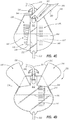
- FIGS. 4A-4D depict another embodiment of a bodily fluid drainage assembly 200.
- Assembly 200 may be configured similarly and may function similarly as assembly 100, described herein.
- Drainage assembly 200 may comprise a fluid bag 210, a first cover 230, a second cover 240, and a third cover 260.
- Fluid bag 210 may comprise an outer edge 211, a front face 212, a seam 213, an upper portion 215, a lower portion 216, a first volume indicator 217, an inlet tube 221, an outlet tube 222, and a hanger 224.
- Fluid bag 210 may comprise one or more pieces a plastic material that are coupled together to form a bag that can retain fluid that has an outer edge 211 that defines a perimeter of the bag. Adjacent to the outer edge is a seam 213 that may be formed by coupling the one or more plastic pieces together via RF welding or any other suitable technique.
- an inlet tube 221 and hanger 224 are located on an upper portion 215 and an outlet tube 222 is located on a lower portion 216 of fluid bag 210.
- At least a portion of fluid bag 210 may be at least partially transparent; for example, at least a portion of front face 212 may be transparent, such that various characteristics of a fluid contained within the fluid bag may be determined.
- First volume indicator 217 may be printed, stamped, or otherwise marked on fluid bag 210. In the depicted embodiment, first volume indicator 217 comprises graduations that demark approximate volumes of a fluid contained within the fluid bag.
- First cover 230 may comprise a partially opaque material that is coupled to fluid bag 210.
- First cover 230 may comprise an outer edge 231, an inner edge 232, a seam 233, perforations 234, and a second volume indicator 235.
- Second volume indicator may comprise a fluid level indicator 236 and graduations 237.
- Second cover 240 may comprise an outer edge 241, an inner edge 242, a seam 243 and perforations 244.
- Third cover 260 may comprise a window cover 261, a window 262, a cutout 263, perforations 264, and outer edges 265.
- Figure 4B depicts bodily fluid bag assembly 200 after the assembly has received some fluid 250.
- Second volume indicator 235 may be configured to function similarly as second volume indicator 135.
- fluid bag 210 may expand and cause outer edge 265 and first cover 230 to slide over each other such that fluid level indicator 236 becomes visible.
- the topmost visible portion of fluid level indicator 236 may correspond with a top level of fluid 250 such that an approximate volume can be determined by correlating the topmost visible portion of fluid level indicator 236 with the nearest graduation 237.
- third cover 260 may comprise a window cover 261, a cutout 263, and perforations 264.
- Window cover 261 may comprise a removable opaque plastic that is the same material from which cover 260 is formed. When window cover 261 is removed, a portion of transparent window 262 is revealed such that fluid 250 can be determined.
- Window 262 may comprise a portion of transparent front face 212 of fluid bag 210 that is visible between opaque first and second covers 230 and 240.
- FIG. 4D depicts bodily fluid drainage bag assembly 200 after third cover 260 has been removed and first and second covers have been partially removed.
- First volume indicator 217 may be used to find an approximate volume of fluid 250 by temporarily lifting or removing second cover 240.
- First and second covers 230 and 240 may be removed by rupturing perforations 234 and 244 such that front face 212 is entirely revealed and at least the portion of fluid 250 nearest the front face of the fluid bag can be visualized.
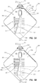
- FIGS. 3A-3C depict another embodiment of a bodily fluid drainage bag 300 from front elevation views, wherein FIG. 3A depicts the assembly, FIG. 3B depicts the assembly after the assembly has received some fluid, and FIG. 3C depicts the assembly after a portion of the assembly has been removed.
- Assembly 300 may be configured similarly and may function similarly as assemblies 100 and/or 200 described herein.
- Assembly 300 may comprise a fluid bag 310, an inlet tube 321, an outlet tube 322, a hanger 324, and a cover 330.
- Fluid bag 310 may comprise an outer edge 311, a front face 312, a first volume indicator 317, a left portion 318, and a right portion 319.
- Outer edge 311 may comprise a perimeter of fluid bag 310 and may at least partially comprise a seam formed by coupling one or more panels of plastic material together to form the fluid bag.
- Front face 312 may comprise an opaque left portion 318 and a transparent right portion 319.
- Left and right portions 318 and 319 are defined strictly for descriptive purposes and the portions themselves and features associated with them may be exchanged or flipped. Left and right portions may or may not define half or approximately half of fluid bag 310 front face 312.
- Front face 312 of fluid bag 310 may comprise a transparent plastic material.
- Right portion 319 is at least partially transparent, except for first volume indicator 317, which may be printed on the right portion.
- First volume indicator 317 comprises graduations that allow for an approximate volume of a fluid within the bag.
- An opaque cover 330 is coupled to fluid bag 310 such that the transparent right portion 319 is obscured.
- Left portion 318 may be rendered opaque by printing, painting, or any other suitable technique and at least a portion of second volume indicator 335 may be printed on the left portion.
- Cover 330 may comprise an outer edge 331, an inner edge 332, a seam 333, and perforations 334.
- Cover 330 comprises an opaque material that is coupled to fluid bag 310 to form seam 333, wherein outer edge 331 is at least partially aligned with a perimeter of the fluid bag.
- Perforations 334 may be formed in cover 330 such that the cover may be removed from assembly 300 to reveal right portion 319 and first volume indicator 317.
- FIG. 5B depicts assembly 300 after the assembly has received a volume of fluid 350.
- Cover 330 is configured to slide over right portion 318 of bag 310 such that a portion of fluid level indicator 336 is revealed, wherein a topmost revealed portion of the fluid level indicator corresponds to the level of fluid 350.
- An approximate volume of fluid 350 may be ascertained by locating a graduation 337 that is adjacent to the topmost revealed portion of fluid level indicator 336. As such, an approximate volume of fluid 350 may be determined without directly viewing fluid 350.
- FIG. 5C depicts assembly 300 after cover 330 has been removed such that transparent right portion 319 of front face 312 is visible.
- An approximate volume of fluid 350 can be determined by comparing the top of the fluid to the nearest graduation on first volume indicator 317. Graduations 337 of second volume indicator 335 may or may not report an accurate approximate volume, when compared directly to the top level of fluid 350.
- FIGS. 6-8 depict alternative embodiments of bodily fluid drainage assemblies from front elevation views, wherein FIG. 6 depicts assembly 400; FIG. 7 depicts assembly 500; FIG. 8 depicts assembly 600: and FIG. 9 depicts assembly 700.
- Assemblies 400, 500, 600, and 700 may be configured similarly and may function similarly as assemblies 100, 200, and/or 300 described herein.
- Assembly 400 may comprise a fluid bag 410, a first cover 430, and a second cover 440. Assembly 400 may further comprise an inlet tube, an outlet tube, and first and second volume indicators as described herein.
- assembly 500 may comprise a fluid bag 510, a first cover 530, and a second cover 540. Assembly 500 may further comprise an inlet tube, an outlet tube, and first and second volume indicators as described herein.
- Assembly 600 may comprise a fluid bag 610, a first cover 630, and a second cover 640. Assembly 600 may further comprise an inlet tube, an outlet tube, and first and second volume indicators as described herein.
- Assembly 700 may comprise a fluid bag 710, a first cover 730, and a second cover 740. Assembly 700 may further comprise an inlet tube, an outlet tube, and first and second volume indicators as described herein.
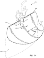
- FIGS. 10-11 depict another embodiment of a bodily fluid drainage assembly 800 from a front elevation view.
- Assembly 800 may be configured similarly to and may function similarly as other bodily fluid drainage assemblies described herein.
- Assembly 800 may comprise a fluid bag 810, a first cover 830, and a second cover, 840.
- Assembly 800 may further comprise an inlet tube 821, an outlet tube (not visible) and a hanger 824.
- the outlet tube may be configured similarly to outlet tube 122, described herein, except that in the depicted embodiment of assembly 800, the outlet tube is located on a rear face of fluid bag 810.
- the outlet tube of assembly 800 is located on a front face of the fluid bag, and in yet another embodiment, the assembly does not comprise an outlet tube.
- the outlet tube may comprise an outlet regulator as is well known in the art.
- Fluid bag 810 may comprise one or more pieces of material coupled together such that a front and a rear face are formed. Front face 812 and a rear face (not visible) may be coupled together at a seam that may be located adjacent to an outer edge of the fluid bag.
- a first volume indicator 817 may be located on a face of fluid bag 810 such that an approximate volume of a liquid 850 may be appreciated. In the depicted embodiment, first volume indicator 817 is located on front face 812.
- First cover 830 and second cover 840 are two such panels, and may comprise opaque pieces of a plastic or fabric material.
- First and second covers 830 and 840 may be coupled to fluid bag 810 via seams 833 and 843.
- Perforations 834 and 844 may be formed in any portion of first and/or second cover 830 and 840 such that one or both of the covers can be removed from the fluid bag.
- perforations 833 and 843 are located adjacent to seams 834 and 844 such that if the covers are removed via the perforations, a majority of the covers are removed from the fluid bag.
- the covers may function together to form a second volume indicator 835, which works similarly to those described herein, wherein the first and second covers slide over each other as the volume of the fluid in the fluid bag increases.
- An approximate volume may be appreciated by identifying the point at which the two covers overlap at their inside edges 832 and 842 and comparing that point to a scale located on one of the covers. In the depicted embodiment, the scale is located on cover 840.
- Removable portions 861 may comprise areas defined by perforations, wherein upon rupturing the perforations, a user may remove the removable portions thereby allowing direct visualization of a fluid within the fluid bag.
- removable portions When removed, removable portions may be said to form windows in the cover and the windows may be formed in predetermined locations such that they may be used to appreciate a minimum volume of fluid in the fluid bag. As such, the removable windows may be said to comprise a third volume indicator.
- the first cover is depicted as lying underneath the second cover; however, one skilled in the art will appreciate that the relationship may be reversed.
- the removable windows are depicted as being on the second cover, whereas in other embodiments, the windows may be located on the first cover or on both covers.
- a gap 870 is defined by inner edges 832 and 842 of the first and second covers 830 and 840 of material. Gap 870 is formed because the covers do not overlap along their entire length. Gap 870 may be employed as a fourth volume indicator, which may also be called a "gap volume indicator". If the volume of fluid is greater than, for example, about 1500 ml, then the second volume indicator may not continue to function; however the fluid level will be visible within gap 870 such that the fluid level can be compared to a scale printed on one of the covers. In this way, an approximate volume can be appreciated via gap 870 if the fluid volume is greater than a predetermined value. The volume at which second volume indicator 865 ceases to function and the fourth volume indicator begins to function may be any predetermined value.
- FIG. 11 depicts assembly 800 from a front elevation view after first and second covers 830 and 840 have been lifted to reveal front face 812 of fluid bag 810, as well as first volume indicator 817, second volume indicator 835, and gap 870. Note that perforations 833 and 843 have not been ruptured and as such, the covers 830 and 840 have not been removed from the assembly; rather, the covers have been lifted. With the covers lifted, an approximate volume of fluid 850 may be appreciated via first volume indicator 817, which in this embodiment comprises a scale located on front face 812 of fluid bag 810.
- FIG. 12 depicts another embodiment of a bodily fluid drainage assembly 900 from a front elevation view.
- Assembly 900 may be configured similarly to and may function similarly as other bodily fluid drainage assemblies described herein.
- Assembly 900 may especially be similar to assembly 800, which is described herein.
- Assembly 900 may comprise a fluid bag 910 with a front face 912, a first cover 930 and a second cover 940.
- An inlet tube 921 and an outlet tube (not visible) may control fluid 950 inflow and outflow.
- a hanger 924 may be directly attached to fluid bag 910.
- Assembly 900 may comprise a first volume indicator 917, a second volume indicator 935, and a gap volume indicator 970. Gap 970 is defined by inner edges 932 and 942. The configurations and functions of these features have been described elsewhere herein.
- First and second covers 930 and 940 may comprise a semitransparent plastic material, such as a clear material that is frosted.
- the covers comprise a transparent material that has been colored as to render it semitransparent or transparent but wherein the fluid appears to have an altered color when viewed through one of the covers.
- one of the covers is semitransparent and the other panel is opaque.
- covers 930 and 940 may be removably coupled to fluid bag 910 at seams 933 and 943. In the depicted embodiment, covers 930 and 940 may be removed via the rupturing of perforations 934 and 944.
- FIG. 13 is a perspective view of an embodiment of a bodily fluid drainage assembly 1000 in accordance with the present claimed invention.
- Assembly 1000 comprises a fluid bag 1010 and a cover 1030.
- Fluid bag 1010 may be configured similarly and may function similarly as other fluid bags described herein.
- fluid bag 1010 may comprise an at least partially translucent material with volume markings indicated such that a fluid contained within the fluid bag may be visualized and an approximate volume estimated.
- Assembly 1000 may also comprise an inlet tube, outlet tube, outlet regulator, and/or a hanger, as described previously herein.
- Cover 1030 may comprise a first volume indicator 1017 and a second volume indicator 1035.
- Cover 1030 may comprise a printed or opaque material, such as a plastic material, which obscures visualization of a fluid contained within fluid bag 1010.
- First volume indicator 1017 may comprise a window 1062 through which a fluid contained in fluid bag 1010 may be visualized.
- First volume indicator 1017 may also comprise graduations that indicate approximate volumes.
- Window 1062 may comprise a removable or cutout portion of cover 1030. If a meniscus of a liquid contained within fluid bag 1010 is visible within window 1062, an approximate volume of the liquid can be ascertained by comparing the meniscus with an adjacent graduation.
- Window 1062 is depicted as being an elongated slot; however, those skilled in the art will recognize that the window may comprise any shape and its size can also vary.
- Second volume indicator 1035 may comprise a cutout 1038 and graduations. Cutout 1038 may comprise a removable or cutout portion of cover 1030. If a meniscus of a liquid contained within fluid bag 1010 is visible within cutout 1038, an approximate volume of the liquid can be ascertained by comparing the meniscus with an adjacent graduation. Cutout 1035 is depicted as a "V" shape; however, those skilled in the art will recognize that the shape of the cutout may vary. Further, the size of the cutout may differ from the depiction.
- Cover 1030 is coupled to fluid bag 1010 at a seam 1033.
- Seam 1033 may be formed via RF welding, gluing, melting, stitching or any other suitable technique. Seam 1033 may include a weakened area that acts like a perforation, so that cover 1030 may be at least partially removable from fluid bag 1010, as described for other covers described herein. Seam 1033 may be formed on one or more sides of assembly 1000. In the depicted embodiment, seam 1033 is formed along a portion of a top side of fluid bag 1010 and cover 1030. As depicted in FIG. 13 , if cover 1030 is not coupled to the fluid bag along one or more adjacent sides, the cover may be at least partially lifted such that the fluid bag can be directly viewed.
- FIG. 14 is a perspective view of bodily fluid drainage assembly 1000, as depicted in FIG. 13 , except that in the depiction of FIG. 14 , cover 1030 is not lifted.
- assembly 1000 may comprise a fluid bag 1010, and a cover 1030.
- Cover 1030 is depicted as having a first and a second volume indicator 1017 and 1035.
- the first volume indicator may comprise a window 1062.
- Second volume indicator 1035 may comprise a cutout 1038.
- FIGS. 15-16 depict cover 1030 of assembly 1000 from a front and side elevation view respectively.
- Cover 1030 comprises a first and second volume indicator 1017 and 1035.
- the first volume indicator may comprise a window 1062.
- Second volume indicator 1035 may comprise a cutout 1038.
- Cover 1030 is configured to cover fluid bag 1010. In the depicted embodiment, the cover overlaps the fluid bag on lateral sides and is approximately even with the fluid bag on the top and bottom sides. In another embodiment, the bottom of the cover that is opposite cutout 1038 extends beyond a bottom edge of the fluid bag.
- cover 16 may comprise a substantially planar shape.
- Any methods disclosed herein comprise one or more steps or actions for performing the described method.
- the method steps and/or actions may be interchanged with one another.
- the order and/or use of specific steps and/or actions may be modified.
Landscapes
- Health & Medical Sciences (AREA)
- Life Sciences & Earth Sciences (AREA)
- Animal Behavior & Ethology (AREA)
- General Health & Medical Sciences (AREA)
- Public Health (AREA)
- Veterinary Medicine (AREA)
- Pharmacology & Pharmacy (AREA)
- Heart & Thoracic Surgery (AREA)
- Biomedical Technology (AREA)
- Engineering & Computer Science (AREA)
- Hematology (AREA)
- Vascular Medicine (AREA)
- Nursing (AREA)
- Orthopedic Medicine & Surgery (AREA)
- Epidemiology (AREA)
- Anesthesiology (AREA)
- External Artificial Organs (AREA)
- Media Introduction/Drainage Providing Device (AREA)
Claims (14)
- Anordnung zur Drainage von Körperflüssigkeit [1000], umfassend:einen Flüssigkeitsbeutel [1010]; undmindestens eine Abdeckung [1030], dadurch gekennzeichnet, dass die Abdeckung mit dem Flüssigkeitsbeutel [1010] an einer Naht [1033] gekoppelt ist, die entlang eines Abschnitts einer Oberseite des Flüssigkeitsbeutels [1010] ausgebildet ist, wobei die Abdeckung [1030] relativ zu dem Flüssigkeitsbeutel [1010] zwischen einer abgedeckten Orientierung beweglich ist, in der die Abdeckung [1030] konfiguriert ist, um die Beobachtung einer innerhalb des Flüssigkeitsbeutels [1010] zurückgehaltenen Flüssigkeit mindestens teilweise zu verdecken, und einer Betrachtungsorientierung, in der ein unteres Ende der Abdeckung [1030] mindestens teilweise derart angehoben werden kann, dass der Flüssigkeitsbeutel [1010] direkt betrachtet werden kann, während ein oberes Ende der Abdeckung [1030] mit dem Flüssigkeitsbeutel [1010] gekoppelt bleibt, wobei die Abdeckung [1030] einen ersten Volumenindikator [1017] umfasst, der ein Betrachten eines Abschnitts des Flüssigkeitsbeutels [1010] durch die Abdeckung [1030] derart ermöglicht, dass ein ungefähres Flüssigkeitsvolumen innerhalb des Flüssigkeitsbeutels [1010] bestimmt werden kann, während sich die Abdeckung [1030] in der abgedeckten Orientierung befindet.
- Anordnung zur Drainage von Körperflüssigkeiten [1000] nach Anspruch 1, wobei der erste Volumenindikator [1017] ein Fenster [1062] umfasst,
- Anordnung zur Drainage von Körperflüssigkeiten [1000] nach Anspruch 2, wobei der erste Volumenindikator [1017] ferner mindestens eine Einteilung umfasst, die ein ungefähres Volumen angibt.
- Anordnung zur Drainage von Körperflüssigkeiten [1000] nach einem der vorhergehenden Ansprüche, wobei der erste Volumenindikator [1017] konfiguriert ist, um ein Bestimmen eines ungefähren Volumens der Flüssigkeit zu ermöglichen, wenn sich die Flüssigkeit innerhalb eines vorgegebenen Bereichs befindet.
- Anordnung zur Drainage von Körperflüssigkeiten [1000] nach einem der vorhergehenden Ansprüche, ferner umfassend einen zweiten Volumenindikator [1035], der konfiguriert ist, um das Bestimmen eines ungefähren Flüssigkeitsvolumens zu ermöglichen, wenn das Flüssigkeitsvolumen größer als der Bereich ist, innerhalb in dem der erste Volumenindikator [1017] zum Schätzen des Volumens der Flüssigkeit verwendet werden kann.
- Anordnung zur Drainage von Körperflüssigkeiten [1000] nach einem der vorhergehenden Ansprüche, ferner umfassend einen zweiten Volumenindikator [1035], der umfasst:
einen Ausschnittabschnitt [1038], der an einen oberen Rand der Abdeckung [1030] angrenzt, der es ermöglicht, die Flüssigkeit zu betrachten, nachdem ein Volumen der Flüssigkeit eine vorgegebene Größe überschritten hat, und mindestens eine Einteilung, die ein ungefähres Volumen angibt. - Anordnung zur Drainage von Körperflüssigkeiten [1000] nach einem der vorhergehenden Ansprüche, wobei die mindestens eine Abdeckung [1030] eine einzelne Materialplatte umfasst, die auf mindestens einer Seite mit dem Flüssigkeitsbeutel [1010] gekoppelt ist.
- Anordnung zur Drainage von Körperflüssigkeiten [1000] nach einem der vorhergehenden Ansprüche, wobei die Abdeckung [1030] derart konfiguriert ist, dass, wenn eine Flüssigkeit innerhalb des Beutels [1010] enthalten ist, die Flüssigkeit durch den ersten Volumenindikator [1017] sichtbar gemacht werden kann, wenn die Abdeckung [1030] nicht angehoben wird.
- Anordnung zur Drainage von Körperflüssigkeiten [1000] nach einem der vorhergehenden Ansprüche, wobei die Abdeckung [1030] ein bedrucktes oder undurchsichtiges Material umfasst.
- Anordnung zur Drainage von Körperflüssigkeiten [1000] nach einem der vorhergehenden Ansprüche, wobei der Flüssigkeitsbeutel [1010] ein mindestens teilweise durchscheinendes Material umfasst.
- Anordnung zur Drainage von Körperflüssigkeiten [1000] nach Anspruch 1, wobei die Naht [1033] eine geschwächte Fläche umfasst, die es ermöglicht, dass die Abdeckung [1030] von dem Flüssigkeitsbeutel [1010] trennbar ist.
- Anordnung zur Drainage von Körperflüssigkeiten [1000] nach Anspruch 11, wobei die geschwächte Fläche Perforierungen umfasst, die zerrissen werden können, um die mindestens eine Abdeckung [1030] zu entfernen.
- Anordnung zur Drainage von Körperflüssigkeiten [1000] nach einem der vorhergehenden Ansprüche, wobei die mindestens eine Abdeckung [1030] entfernbar mit dem Flüssigkeitsbeutel [1010] gekoppelt ist.
- Anordnung zur Drainage von Körperflüssigkeiten [1000] nach einem der vorhergehenden Ansprüche, wobei der Flüssigkeitsbeutel [1010] ferner ein Einlassrohr, ein Auslassrohr, einen Ausgangsregler und eine Aufhängung umfasst.
Applications Claiming Priority (4)
| Application Number | Priority Date | Filing Date | Title |
|---|---|---|---|
| US12/253,714 US8092436B2 (en) | 2008-10-17 | 2008-10-17 | Bodily fluid drainage assembly |
| US14332709P | 2009-01-08 | 2009-01-08 | |
| US18424009P | 2009-06-04 | 2009-06-04 | |
| PCT/US2009/059482 WO2010045042A2 (en) | 2008-10-17 | 2009-10-05 | Bodily fluid drainage assembly |
Publications (3)
| Publication Number | Publication Date |
|---|---|
| EP2346546A2 EP2346546A2 (de) | 2011-07-27 |
| EP2346546A4 EP2346546A4 (de) | 2018-03-21 |
| EP2346546B1 true EP2346546B1 (de) | 2020-08-12 |
Family
ID=42107133
Family Applications (1)
| Application Number | Title | Priority Date | Filing Date |
|---|---|---|---|
| EP09821003.2A Active EP2346546B1 (de) | 2008-10-17 | 2009-10-05 | Drainageanordnung für körperflüssigkeiten |
Country Status (3)
| Country | Link |
|---|---|
| US (7) | US8790320B2 (de) |
| EP (1) | EP2346546B1 (de) |
| WO (1) | WO2010045042A2 (de) |
Families Citing this family (93)
| Publication number | Priority date | Publication date | Assignee | Title |
|---|---|---|---|---|
| US8430855B2 (en) * | 2006-12-06 | 2013-04-30 | Medline Industries, Inc. | Fluid collection system and methods of using same |
| US9066807B2 (en) | 2007-04-24 | 2015-06-30 | Jpmorgan Chase Bank, N.A. | Closure system for a drainable pouch |
| CA2689582C (en) | 2007-06-12 | 2016-08-09 | Convatec Technologies Inc. | Ostomy appliance |
| EP2346546B1 (de) | 2008-10-17 | 2020-08-12 | Sterigear LLC | Drainageanordnung für körperflüssigkeiten |
| AU2009316291B2 (en) | 2008-11-19 | 2015-09-17 | Convatec Technologies Inc. | Ostomy pouch appliance |
| US10294317B2 (en) | 2009-07-07 | 2019-05-21 | Convatec Technologies Inc. | Pressure sensitive adhesives with amphiphilic copolymers |
| JP5738866B2 (ja) | 2009-09-11 | 2015-06-24 | コンバテック・テクノロジーズ・インコーポレイテッドConvatec Technologies Inc | 排出制御造瘻術用器具およびそのためのシールド |
| US10285847B2 (en) | 2011-09-29 | 2019-05-14 | Convatec Technologies Inc. | Ostomy pouch with filtering system |
| GB201115160D0 (en) | 2011-09-02 | 2011-10-19 | Trio Healthcare Ltd | Discharge solidifier and malodour control |
| JP3175719U (ja) * | 2012-03-07 | 2012-05-24 | 一夫 太刀川 | 糞尿袋 |
| US20140194855A1 (en) * | 2013-01-04 | 2014-07-10 | Abdallah K Kayyal | Intravenous Therapy System and Method |
| US10226376B2 (en) | 2014-03-19 | 2019-03-12 | Purewick Corporation | Apparatus and methods for receiving discharged urine |
| US11806266B2 (en) | 2014-03-19 | 2023-11-07 | Purewick Corporation | Apparatus and methods for receiving discharged urine |
| US10390989B2 (en) | 2014-03-19 | 2019-08-27 | Purewick Corporation | Apparatus and methods for receiving discharged urine |
| US11376152B2 (en) | 2014-03-19 | 2022-07-05 | Purewick Corporation | Apparatus and methods for receiving discharged urine |
| US10952889B2 (en) | 2016-06-02 | 2021-03-23 | Purewick Corporation | Using wicking material to collect liquid for transport |
| WO2015164832A1 (en) | 2014-04-24 | 2015-10-29 | Convatec Technologies Inc. | Ostomy pouch filter system |
| CA2975255C (en) | 2015-02-02 | 2021-01-05 | C.R. Bard, Inc. | Drainage bag systems including at least one indicator element and methods of using the same |
| WO2017023794A1 (en) | 2015-07-31 | 2017-02-09 | Medivance Incorporated | Urine output collection and monitoring system |
| JP6929838B2 (ja) | 2015-10-14 | 2021-09-01 | コンバテック・テクノロジーズ・インコーポレイテッドConvatec Technologies Inc | 開口システムを有する医療装置 |
| US12042420B2 (en) | 2016-05-04 | 2024-07-23 | Cheryl A. Mitts | Urine collection bag assembly |
| US9867731B2 (en) * | 2016-05-04 | 2018-01-16 | Cheryl Mitts | Urine collection bag assembly |
| US10973678B2 (en) | 2016-07-27 | 2021-04-13 | Purewick Corporation | Apparatus and methods for receiving discharged urine |
| US10376406B2 (en) | 2016-07-27 | 2019-08-13 | Purewick Corporation | Male urine collection device using wicking material |
| EP4635457A3 (de) * | 2016-09-14 | 2025-12-10 | Curas Ltd. | Drainagebeutelsystem, aufnahmebeutel und verfahren zum entleeren eines urindrainagebeutels |
| CN110612075B (zh) | 2017-01-31 | 2022-09-09 | 普利维克公司 | 用于接收排出的尿液的装置和方法 |
| WO2019212949A1 (en) | 2018-05-01 | 2019-11-07 | Purewick Corporation | Fluid collection devices, systems, and methods |
| CN112367949B (zh) | 2018-05-01 | 2023-09-12 | 普利维克公司 | 流体收集装置、相关系统及相关方法 |
| KR102492111B1 (ko) | 2018-05-01 | 2023-01-27 | 퓨어윅 코포레이션 | 유체 수집 장치 및 이를 사용하는 방법 |
| KR102493455B1 (ko) | 2018-05-01 | 2023-01-31 | 퓨어윅 코포레이션 | 유체 수집 장치, 관련 시스템 및 관련 방법 |
| EP3787569B1 (de) | 2018-05-01 | 2025-07-16 | Purewick Corporation | Flüssigkeitssammelvorrichtungen und -systeme |
| EP3784322B1 (de) | 2018-05-22 | 2023-11-22 | C. R. Bard, Inc. | Katheterisierungssystem und anwendungsverfahren dafür |
| EP3833257B1 (de) | 2018-08-10 | 2025-09-24 | C. R. Bard, Inc. | Automatisierte urinproduktionsmesssysteme und verfahren dafür |
| EP3692956A1 (de) | 2019-02-07 | 2020-08-12 | ConvaTec Technologies Inc. | Einstellbare konvexe stomavorrichtung |
| US11730875B2 (en) | 2019-04-01 | 2023-08-22 | Sterigear, Llc | Dual drainage bag, assemblies, and related methods |
| BR112021021315A2 (pt) | 2019-04-25 | 2022-01-18 | Convatec Technologies Inc | Placas de ostomia incorporando adesivos e camadas de espuma, dispositivos incluindo as mesmas e métodos de aplicação |
| SG11202111675TA (en) | 2019-04-25 | 2021-11-29 | Convatec Technologies Inc | Perforated chamber ostomy wafers,devices including the same, and methods of applying |
| US11590017B2 (en) | 2019-04-25 | 2023-02-28 | Convatec Technologies Inc. | Ostomy wafers incorporating adhesives, ostomy devices including the same, and methods of applying ostomy wafers and ostomy devices |
| WO2020256865A1 (en) | 2019-06-21 | 2020-12-24 | Purewick Corporation | Fluid collection devices including a base securement area, and related systems and methods |
| CN114375187A (zh) | 2019-07-11 | 2022-04-19 | 普奥维克有限公司 | 流体收集装置、系统和方法 |
| EP3999003B1 (de) | 2019-07-19 | 2024-05-01 | Purewick Corporation | Fluidsammelvorrichtungen mit mindestens einem formgedächtnismaterial |
| CN110731852A (zh) * | 2019-10-17 | 2020-01-31 | 山东大学齐鲁医院 | 一种便捷可视化电子计量尿袋 |
| CN114867435B (zh) | 2019-10-28 | 2025-12-23 | 普利维克公司 | 包括样本端口的流体收集组件 |
| US11389321B2 (en) * | 2019-11-19 | 2022-07-19 | Michael Cooks | Female catheter assembly |
| EP4084746B1 (de) | 2020-01-03 | 2025-04-02 | Purewick Corporation | Urinsammelvorrichtungen mit einem relativ breiten abschnitt und einem länglichen teil und zugehörige verfahren |
| US12589022B2 (en) | 2020-03-19 | 2026-03-31 | Purewick Corporation | Fluid collection assemblies including one or more movement enhancing features |
| EP4344685B1 (de) | 2020-04-10 | 2025-06-11 | Purewick Corporation | Flüssigkeitssammelanordnungen mit einer oder mehreren leckverhinderungsmerkmalen |
| WO2021211729A1 (en) | 2020-04-17 | 2021-10-21 | Purewick Corporation | Fluid collection devices, systems, and methods securing a protruding portion in position for use |
| US12447042B2 (en) | 2020-04-17 | 2025-10-21 | Purewick Corporation | Fluid collection assemblies including a fluid impermeable barrier having a sump and a base |
| WO2021211599A1 (en) | 2020-04-17 | 2021-10-21 | Purewick Corporation | Female external catheter devices having a urethral cup, and related systems and methods |
| WO2021216422A1 (en) | 2020-04-20 | 2021-10-28 | Purewick Corporation | Fluid collection devices adjustable between a vacuum- based orientation and a gravity-based orientation, and related systems and methods |
| US12048643B2 (en) | 2020-05-27 | 2024-07-30 | Purewick Corporation | Fluid collection assemblies including at least one inflation device and methods and systems of using the same |
| US12083261B2 (en) | 2020-06-05 | 2024-09-10 | C. R. Bard, Inc. | Automated fluid output monitoring |
| US11703365B2 (en) | 2020-07-14 | 2023-07-18 | C. R. Bard, Inc. | Automatic fluid flow system with push-button connection |
| US12055249B2 (en) | 2020-07-21 | 2024-08-06 | C. R. Bard, Inc. | Automatic fluid flow system with retractable connection |
| WO2022031943A1 (en) | 2020-08-06 | 2022-02-10 | Purewick Corporation | A fluid collection system including a garment and a fluid collection device |
| US20220047410A1 (en) | 2020-08-11 | 2022-02-17 | Purewick Corporation | Fluid collection assemblies defining waist and leg openings |
| US12521272B2 (en) | 2020-09-09 | 2026-01-13 | Purewick Corporation | Fluid collection devices, systems, and methods |
| US11801186B2 (en) | 2020-09-10 | 2023-10-31 | Purewick Corporation | Urine storage container handle and lid accessories |
| US12156792B2 (en) | 2020-09-10 | 2024-12-03 | Purewick Corporation | Fluid collection assemblies including at least one inflation device |
| US12042423B2 (en) | 2020-10-07 | 2024-07-23 | Purewick Corporation | Fluid collection systems including at least one tensioning element |
| US12569365B2 (en) | 2020-10-21 | 2026-03-10 | Purewick Corporation | Fluid collection assemblies including at least one shape memory material disposed in the conduit |
| US12257174B2 (en) | 2020-10-21 | 2025-03-25 | Purewick Corporation | Fluid collection assemblies including at least one of a protrusion or at least one expandable material |
| US12440370B2 (en) | 2020-10-21 | 2025-10-14 | Purewick Corporation | Apparatus with compressible casing for receiving discharged urine |
| US12208031B2 (en) | 2020-10-21 | 2025-01-28 | Purewick Corporation | Adapters for fluid collection devices |
| US12048644B2 (en) | 2020-11-03 | 2024-07-30 | Purewick Corporation | Apparatus for receiving discharged urine |
| US12070432B2 (en) | 2020-11-11 | 2024-08-27 | Purewick Corporation | Urine collection system including a flow meter and related methods |
| US12245967B2 (en) | 2020-11-18 | 2025-03-11 | Purewick Corporation | Fluid collection assemblies including an adjustable spine |
| US12558474B2 (en) | 2020-11-19 | 2026-02-24 | C. R. Bard, Inc. | Dynamic pressure response system |
| US12408853B2 (en) | 2020-12-17 | 2025-09-09 | C. R. Bard, Inc. | Smart bag to measure urine output via catheter |
| US12364423B2 (en) | 2020-12-21 | 2025-07-22 | C. R. Bard, Inc. | Automated urinary output-measuring systems and methods |
| US11931151B2 (en) | 2020-12-22 | 2024-03-19 | C. R. Bard, Inc. | Automated urinary output measuring system |
| US12246146B2 (en) | 2020-12-23 | 2025-03-11 | C. R. Bard, Inc. | Automated weight based fluid output monitoring system |
| US12599495B2 (en) | 2021-01-05 | 2026-04-14 | Purewick Corporation | Male external catheter with attachment interface configured to bias against penis |
| US12268627B2 (en) | 2021-01-06 | 2025-04-08 | Purewick Corporation | Fluid collection assemblies including at least one securement body |
| JP2024503636A (ja) | 2021-01-07 | 2024-01-26 | ピュアウィック コーポレイション | 車椅子に固定可能な尿収集システムおよび関連する方法 |
| JP7500744B2 (ja) | 2021-01-19 | 2024-06-17 | ピュアウィック コーポレイション | 可変流体収集デバイス、システム、及び方法 |
| US12178735B2 (en) | 2021-02-09 | 2024-12-31 | Purewick Corporation | Noise reduction for a urine suction system |
| CN116615162A (zh) | 2021-02-26 | 2023-08-18 | 普奥维克有限公司 | 在管口与屏障之间具有储液槽的流体收集装置以及相关系统和方法 |
| US12551385B2 (en) | 2021-03-05 | 2026-02-17 | Purewick Corporation | Fluid collection assembly including a tube having porous wicking material for improved fluid transport |
| US12558472B2 (en) | 2021-03-05 | 2026-02-24 | Purewick Corporation | Portable fluid collection systems with storage and related methods |
| US12458525B2 (en) | 2021-03-10 | 2025-11-04 | Purewick Corporation | Acoustic silencer for a urine suction system |
| US12029677B2 (en) | 2021-04-06 | 2024-07-09 | Purewick Corporation | Fluid collection devices having a collection bag, and related systems and methods |
| JP7642864B2 (ja) * | 2021-04-29 | 2025-03-10 | ピュアウィック コーポレイション | 少なくとも1つの流体検出器を有する排液バッグ |
| US12233003B2 (en) | 2021-04-29 | 2025-02-25 | Purewick Corporation | Fluid collection assemblies including at least one length adjusting feature |
| US12251333B2 (en) | 2021-05-21 | 2025-03-18 | Purewick Corporation | Fluid collection assemblies including at least one inflation device and methods and systems of using the same |
| US12324767B2 (en) | 2021-05-24 | 2025-06-10 | Purewick Corporation | Fluid collection assembly including a customizable external support and related methods |
| US12150885B2 (en) | 2021-05-26 | 2024-11-26 | Purewick Corporation | Fluid collection system including a cleaning system and methods |
| US12575960B2 (en) | 2021-06-24 | 2026-03-17 | Purewick Corporation | Urine collection systems having one or more of volume, pressure, or flow indicators, and related methods |
| US12551366B2 (en) | 2021-08-02 | 2026-02-17 | Purewick Corporation | Fluid collection devices having multiple fluid collection regions, and related systems and methods |
| US12446813B2 (en) | 2021-08-23 | 2025-10-21 | C. R. Bard, Inc. | Automated urine output system for attachment to hospital bed |
| US12594062B2 (en) | 2021-09-08 | 2026-04-07 | Purewick Corporation | Fluid collection assemblies including an extension |
| GB2620397A (en) * | 2022-07-05 | 2024-01-10 | Clinisupplies Ltd | A catheter bag and connections and accessories therefor |
Family Cites Families (86)
| Publication number | Priority date | Publication date | Assignee | Title |
|---|---|---|---|---|
| US3253593A (en) * | 1963-12-03 | 1966-05-31 | Macbick Company | Urinary drainage system and parts thereof |
| US3601125A (en) * | 1969-05-23 | 1971-08-24 | David H Moss | Body-worn urinal for females |
| US3973565A (en) | 1973-07-20 | 1976-08-10 | Everett Medical Products Limited | Winged cannula with skin securing means |
| US4095589A (en) | 1975-05-20 | 1978-06-20 | Plastronics, Inc. | Combination urine meter and drainage receptacle |
| US4122851A (en) * | 1976-05-13 | 1978-10-31 | Grossner Dolores E | Carrier and skin-protecting cover for urine bags |
| CA1063981A (en) | 1976-12-13 | 1979-10-09 | Willis M. Morris | Envelope and form assembly |
| US4173979A (en) | 1977-06-10 | 1979-11-13 | Odis Johnnie M | Urine bag cover and holder device |
| US4312352A (en) | 1980-01-29 | 1982-01-26 | C. R. Bard, Inc. | Hanger, hook and handle assembly for urinary drainage bag |
| US4343316A (en) | 1980-05-16 | 1982-08-10 | C. R. Bard, Inc. | Electronic urine flow monitor |
| GB2109770B (en) * | 1981-11-23 | 1986-02-12 | Graig Med Prod Ltd | Drainage bag and manufacture of same |
| US4417892A (en) | 1981-12-31 | 1983-11-29 | C. R. Bard, Inc. | Urine drainage bag outlet tube and method for eliminating or reducing migration of bacteria |
| US4460362A (en) | 1982-07-21 | 1984-07-17 | The Kendall Company | Drainage system with holding chamber |
| US4526576A (en) | 1983-01-27 | 1985-07-02 | The Kendall Company | Liquid drainage system with interlocked handle |
| US4562984A (en) | 1983-08-08 | 1986-01-07 | Sherwood Medical Company | Drainage bag support |
| US4625734A (en) | 1984-08-06 | 1986-12-02 | Sherwood Medical Company | Urine meter and drainage bag combination |
| US4606736A (en) | 1985-01-23 | 1986-08-19 | Van De Weghe Associates, Inc. | Cover assembly for closed bodily fluid drainage unit |
| USD296360S (en) | 1985-05-06 | 1988-06-21 | Professional Medical Products, Inc. | Urine meter |
| US5226564A (en) | 1986-11-28 | 1993-07-13 | E. R. Squibb & Sons, Inc. | Manufacture of bags |
| US5531724A (en) | 1987-01-14 | 1996-07-02 | American Innotek, Inc. | Fluid containment bag |
| USD310721S (en) | 1988-02-16 | 1990-09-18 | Genetic Laboratories, Inc. | Nose tube anchoring strip |
| DE8804685U1 (de) | 1988-04-08 | 1988-05-19 | INDAG Gesellschaft für Industriebedarf mbH, 6900 Heidelberg | Sprühgerät |
| US4874387A (en) * | 1988-11-01 | 1989-10-17 | Boone Delores A | Cover for body fluid drainage bag and tubing |
| US4936837A (en) | 1988-11-04 | 1990-06-26 | C. R. Bard, Inc. | Aseptic drainage outlet |
| US5046195A (en) | 1989-09-08 | 1991-09-10 | Cap-Mate Company | Head band with neck shield |
| US5176665A (en) | 1991-01-18 | 1993-01-05 | Alza Corporation | Antimicrobial device for urine drainage container |
| US5263946A (en) | 1991-05-06 | 1993-11-23 | Sierra Laboratories, Inc. | Latex urine container having odor impermeable treatment and provided with integral strap holders |
| US5211642A (en) | 1991-10-28 | 1993-05-18 | Clendenning Beverly F | Chambers drainage system |
| US5454797A (en) | 1994-08-12 | 1995-10-03 | Haswell; John N. | Combined pelvic tray, workstation and fluid collection device |
| US5496299A (en) | 1994-09-21 | 1996-03-05 | C. R. Bard, Inc. | Suction reservoir |
| US5725515A (en) | 1994-11-01 | 1998-03-10 | Tri-State Hospital Supply Corporation | Urine sampling and bladder drainage system |
| USD369662S (en) | 1994-11-07 | 1996-05-07 | Kuentz Etha A | Ostomy pouch support bag |
| USD375355S (en) | 1995-03-14 | 1996-11-05 | Venetec International, Inc. | Anchor pad with release layer |
| US5686096A (en) | 1995-12-22 | 1997-11-11 | Becton Dickinson And Company | Medical device for the protection of a catheter penetration site |
| USD377115S (en) | 1996-01-29 | 1997-01-07 | Feriend L Ann | Bag cover for a bodily fluid drainage pouch |
| USD391483S (en) | 1996-07-05 | 1998-03-03 | Freeman Janie B | Bottle apron |
| USD398990S (en) | 1996-11-14 | 1998-09-29 | Smiths Industries Plc | Stoma bag |
| US5759180A (en) * | 1997-01-27 | 1998-06-02 | Myhres; Donita F. | Ostomy bag cover and assembly |
| US6132407A (en) | 1997-02-06 | 2000-10-17 | C. R. Bard, Inc. | Outlet tube device for urinary drainage bag |
| US6467953B1 (en) | 1999-03-30 | 2002-10-22 | Medical Solutions, Inc. | Method and apparatus for monitoring temperature of intravenously delivered fluids and other medical items |
| DE19733278C2 (de) | 1997-08-01 | 1999-11-11 | Storz Endoskop Gmbh | Druckbehälter zum Beaufschlagen eines in diesem aufgenommenen, mit einer medizinischen Flüssigkeit gefüllten flexiblen Beutels mit Druck |
| US6053905A (en) | 1998-02-23 | 2000-04-25 | Tyco International (Us) Inc. | Self contained urethral catheter assembly with lubricating chamber |
| US20020077609A1 (en) | 1998-07-07 | 2002-06-20 | Madeline Johnson | Disposable urinary collection bag cover |
| US6261254B1 (en) | 1999-07-21 | 2001-07-17 | C. R. Bard, Inc. | Lever-style drain assembly for urine collection container |
| US6709420B1 (en) | 1999-07-21 | 2004-03-23 | C.R. Bard, Inc. | Switch-style drain assembly for urine collection container |
| TW475732U (en) * | 1999-12-18 | 2002-02-01 | Umax Data Systems Inc | System with enhanced usable range in axial direction of light source |
| DE60118881T2 (de) | 2000-01-28 | 2006-11-30 | Coloplast A/S | Sammelbeutel |
| US6613036B1 (en) | 2000-02-01 | 2003-09-02 | Abbott Laboratories | Light-protective container assembly and method of making same |
| USD438616S1 (en) | 2000-04-28 | 2001-03-06 | Shirley A Williams | Urine bag cover |
| USD458687S1 (en) | 2000-09-29 | 2002-06-11 | Cynthia Mary Dale | Dressing |
| US7001370B2 (en) | 2001-01-31 | 2006-02-21 | Mentor Corporation | Urine collection bags for urinary catheter systems |
| DK174694B1 (da) | 2001-05-21 | 2003-09-15 | Coloplast As | Stomipose med et dække af porøst materiale |
| CN100405995C (zh) * | 2001-06-29 | 2008-07-30 | 科洛普拉斯特公司 | 导尿管装置 |
| US6612432B2 (en) * | 2001-10-15 | 2003-09-02 | W. David Motson | Universal case for portable electronic device |
| USD467414S1 (en) | 2001-10-16 | 2002-12-24 | Pharmacia Ab | Container for medical instruments |
| USD470586S1 (en) | 2001-12-21 | 2003-02-18 | Brenda J Felstet | Catheter bag cover |
| US6846847B2 (en) | 2002-07-24 | 2005-01-25 | James G. Holwerda | Biocidal agents and methods of use |
| US7147627B2 (en) | 2002-08-21 | 2006-12-12 | Hollister Incorporated | Bowel management system |
| SE523744C2 (sv) * | 2002-09-06 | 2004-05-11 | Gambro Lundia Ab | Behållare för dialysfluid och ett förfarande för tillverkning av en sådan behållare |
| USD482063S1 (en) | 2002-09-25 | 2003-11-11 | Xerox Corporation | Color ink stick for solid ink printer |
| US6955272B2 (en) | 2003-03-03 | 2005-10-18 | Collins Lisa B | Baby bottle bib |
| US20050059952A1 (en) | 2003-09-17 | 2005-03-17 | Giuliano Amy S. | I.V. solution bag with a needleless port |
| USD502557S1 (en) | 2004-02-18 | 2005-03-01 | Tennessee Mat Company, Inc. | Section of interlocking modular floor tile |
| USD515699S1 (en) | 2004-03-09 | 2006-02-21 | Barbara Girod | Drainage bag cover |
| US7513894B2 (en) | 2004-07-08 | 2009-04-07 | Jim Howlett | Human body fluid collection bag |
| US20060111681A1 (en) | 2004-11-08 | 2006-05-25 | Vernon Robert D | Free-standing urine collection bag and urine bag system |
| USD537948S1 (en) | 2005-01-31 | 2007-03-06 | Patricia Ann Smith | Tri-lobe planar heel wound dressing |
| USD552732S1 (en) | 2005-07-13 | 2007-10-09 | Venetec International, Inc. | Anchor pad |
| US20070203463A1 (en) | 2006-02-24 | 2007-08-30 | Larry Salvadori | Urine collection system with needleless sampling port |
| US20070203464A1 (en) | 2006-02-24 | 2007-08-30 | Green Kurt E | Urine collection bag with integral anti-reflux valve |
| US7500968B1 (en) | 2006-03-06 | 2009-03-10 | Nappa Thomas P | Unidirectional urine collection reservoir |
| JP2007319283A (ja) | 2006-05-31 | 2007-12-13 | Nippon Sherwood Medical Industries Ltd | 医療用バッグ |
| US7645968B2 (en) | 2006-06-30 | 2010-01-12 | Tyco Healthcare Group Lp | Method for securing a urine meter to a urine bag |
| US7846142B2 (en) | 2006-12-06 | 2010-12-07 | Medline Industries, Inc. | Fluid collection system and methods of using same |
| US8216207B2 (en) | 2007-08-01 | 2012-07-10 | Hospira, Inc. | Medicament admixing system |
| US20090088709A1 (en) | 2007-09-27 | 2009-04-02 | Salvadori Lawrence A | Illuminated fluid collection bag |
| WO2009078196A1 (ja) * | 2007-12-18 | 2009-06-25 | Yushin Co., Ltd. | 非自立型液状物充填包装体用容器 |
| USD609802S1 (en) | 2008-02-04 | 2010-02-09 | Inova Medical Ag | Self-closing external vascular closure |
| US8361044B2 (en) * | 2008-03-14 | 2013-01-29 | Mary Marshall Enterprises, Inc. | Methods and devices for concealing and securing a urine collection bag |
| USD601707S1 (en) | 2008-05-06 | 2009-10-06 | Laboratoires Urgo | Adhesive dressing |
| USD684687S1 (en) | 2008-10-17 | 2013-06-18 | Sterigear LLC | Bodily fluid drainage bag cover |
| EP2346546B1 (de) * | 2008-10-17 | 2020-08-12 | Sterigear LLC | Drainageanordnung für körperflüssigkeiten |
| US8092436B2 (en) | 2008-10-17 | 2012-01-10 | Sterigear LLC | Bodily fluid drainage assembly |
| USD684688S1 (en) | 2008-10-17 | 2013-06-18 | Sterigear LLC | Bodily fluid drainage bag cover |
| USD612937S1 (en) | 2009-06-04 | 2010-03-30 | Sterigear LLC | Bodily fluid drainage bag cover |
| USD612060S1 (en) | 2009-09-03 | 2010-03-16 | Smith Patricia A | Sacral wound dressing |
| USD673266S1 (en) | 2010-12-17 | 2012-12-25 | Carefusion 2200, Inc. | Catheter patch |
-
2009
- 2009-10-05 EP EP09821003.2A patent/EP2346546B1/de active Active
- 2009-10-05 WO PCT/US2009/059482 patent/WO2010045042A2/en not_active Ceased
-
2011
- 2011-04-17 US US13/088,409 patent/US8790320B2/en active Active
-
2014
- 2014-07-28 US US14/444,271 patent/US11090415B2/en active Active
-
2020
- 2020-01-27 US US16/773,611 patent/US11497842B2/en active Active
- 2020-10-30 US US17/086,195 patent/US11865244B2/en active Active
-
2021
- 2021-05-17 US US17/322,766 patent/US20220008638A1/en not_active Abandoned
- 2021-05-17 US US17/322,772 patent/US20220008639A1/en not_active Abandoned
-
2024
- 2024-01-17 US US18/415,593 patent/US20240325618A1/en active Pending
Non-Patent Citations (1)
| Title |
|---|
| None * |
Also Published As
| Publication number | Publication date |
|---|---|
| US20200155735A1 (en) | 2020-05-21 |
| US11090415B2 (en) | 2021-08-17 |
| US20140336598A1 (en) | 2014-11-13 |
| US20220008638A1 (en) | 2022-01-13 |
| US20220008639A1 (en) | 2022-01-13 |
| EP2346546A2 (de) | 2011-07-27 |
| US20210146017A1 (en) | 2021-05-20 |
| US11865244B2 (en) | 2024-01-09 |
| WO2010045042A3 (en) | 2010-07-08 |
| US8790320B2 (en) | 2014-07-29 |
| US20120041400A1 (en) | 2012-02-16 |
| WO2010045042A2 (en) | 2010-04-22 |
| US20240325618A1 (en) | 2024-10-03 |
| EP2346546A4 (de) | 2018-03-21 |
| US11497842B2 (en) | 2022-11-15 |
Similar Documents
| Publication | Publication Date | Title |
|---|---|---|
| EP2346546B1 (de) | Drainageanordnung für körperflüssigkeiten | |
| US8092436B2 (en) | Bodily fluid drainage assembly | |
| US12403233B2 (en) | Dual drainage bag, assemblies, and related methods | |
| CN108366870B (zh) | 具有开孔系统的医疗设备 | |
| EP1996269B1 (de) | Chirurgiekassette mit mehrbereichsflüssigkeitskammer | |
| CA1306160C (en) | Body fluid collection device | |
| US20170105707A1 (en) | Sample collector | |
| EP0401951A1 (de) | Filtervorrichtung | |
| SG185598A1 (en) | Soft medical container and nutrient supply system using same | |
| MXPA04010482A (es) | Empaque de dispositivo medico de apertura automatica y metodo de fabricacion. | |
| US5048976A (en) | Carrier bag | |
| EP4037623B1 (de) | Ostomievorrichtung | |
| JP4524398B2 (ja) | 点滴容器包装袋 | |
| US20100290718A1 (en) | Frangible seals for multiple compartment bags, multiple compartment bags incorporating the same, and methods of forming the same | |
| DK166945B1 (da) | Urinpose med ophaeng | |
| EP4355276B1 (de) | Ostomiebeutel mit sichtoptionsfunktion | |
| JP2005296213A (ja) | ドリッパー | |
| JPS5810615A (ja) | 流体の流出,収集のための容器 | |
| CN211834726U (zh) | 一种手术器械挂袋 | |
| WO2020138504A1 (ja) | 経腸栄養バッグ及び経腸栄養バッグの製造方法 | |
| CN219407586U (zh) | 包装袋 | |
| JP3140972U (ja) | 薬収容体 | |
| CN117580552A (zh) | 具有至少一个流体检测器的引流袋 | |
| JP2000271211A (ja) | 採血用チューブ | |
| JPS609160Y2 (ja) | 袋体 |
Legal Events
| Date | Code | Title | Description |
|---|---|---|---|
| PUAI | Public reference made under article 153(3) epc to a published international application that has entered the european phase |
Free format text: ORIGINAL CODE: 0009012 |
|
| 17P | Request for examination filed |
Effective date: 20110516 |
|
| AK | Designated contracting states |
Kind code of ref document: A2 Designated state(s): AT BE BG CH CY CZ DE DK EE ES FI FR GB GR HR HU IE IS IT LI LT LU LV MC MK MT NL NO PL PT RO SE SI SK SM TR |
|
| AX | Request for extension of the european patent |
Extension state: AL BA RS |
|
| DAX | Request for extension of the european patent (deleted) | ||
| A4 | Supplementary search report drawn up and despatched |
Effective date: 20180220 |
|
| RIC1 | Information provided on ipc code assigned before grant |
Ipc: A61M 1/00 20060101AFI20180214BHEP Ipc: A61J 1/10 20060101ALI20180214BHEP Ipc: A61F 5/44 20060101ALI20180214BHEP |
|
| STAA | Information on the status of an ep patent application or granted ep patent |
Free format text: STATUS: EXAMINATION IS IN PROGRESS |
|
| 17Q | First examination report despatched |
Effective date: 20181119 |
|
| GRAP | Despatch of communication of intention to grant a patent |
Free format text: ORIGINAL CODE: EPIDOSNIGR1 |
|
| STAA | Information on the status of an ep patent application or granted ep patent |
Free format text: STATUS: GRANT OF PATENT IS INTENDED |
|
| INTG | Intention to grant announced |
Effective date: 20200227 |
|
| GRAS | Grant fee paid |
Free format text: ORIGINAL CODE: EPIDOSNIGR3 |
|
| GRAA | (expected) grant |
Free format text: ORIGINAL CODE: 0009210 |
|
| STAA | Information on the status of an ep patent application or granted ep patent |
Free format text: STATUS: THE PATENT HAS BEEN GRANTED |
|
| AK | Designated contracting states |
Kind code of ref document: B1 Designated state(s): AT BE BG CH CY CZ DE DK EE ES FI FR GB GR HR HU IE IS IT LI LT LU LV MC MK MT NL NO PL PT RO SE SI SK SM TR |
|
| REG | Reference to a national code |
Ref country code: GB Ref legal event code: FG4D |
|
| REG | Reference to a national code |
Ref country code: CH Ref legal event code: EP |
|
| REG | Reference to a national code |
Ref country code: DE Ref legal event code: R096 Ref document number: 602009062609 Country of ref document: DE |
|
| REG | Reference to a national code |
Ref country code: IE Ref legal event code: FG4D |
|
| REG | Reference to a national code |
Ref country code: AT Ref legal event code: REF Ref document number: 1300888 Country of ref document: AT Kind code of ref document: T Effective date: 20200915 |
|
| REG | Reference to a national code |
Ref country code: LT Ref legal event code: MG4D |
|
| REG | Reference to a national code |
Ref country code: NL Ref legal event code: MP Effective date: 20200812 |
|
| PG25 | Lapsed in a contracting state [announced via postgrant information from national office to epo] |
Ref country code: GR Free format text: LAPSE BECAUSE OF FAILURE TO SUBMIT A TRANSLATION OF THE DESCRIPTION OR TO PAY THE FEE WITHIN THE PRESCRIBED TIME-LIMIT Effective date: 20201113 Ref country code: NO Free format text: LAPSE BECAUSE OF FAILURE TO SUBMIT A TRANSLATION OF THE DESCRIPTION OR TO PAY THE FEE WITHIN THE PRESCRIBED TIME-LIMIT Effective date: 20201112 Ref country code: ES Free format text: LAPSE BECAUSE OF FAILURE TO SUBMIT A TRANSLATION OF THE DESCRIPTION OR TO PAY THE FEE WITHIN THE PRESCRIBED TIME-LIMIT Effective date: 20200812 Ref country code: HR Free format text: LAPSE BECAUSE OF FAILURE TO SUBMIT A TRANSLATION OF THE DESCRIPTION OR TO PAY THE FEE WITHIN THE PRESCRIBED TIME-LIMIT Effective date: 20200812 Ref country code: SE Free format text: LAPSE BECAUSE OF FAILURE TO SUBMIT A TRANSLATION OF THE DESCRIPTION OR TO PAY THE FEE WITHIN THE PRESCRIBED TIME-LIMIT Effective date: 20200812 Ref country code: FI Free format text: LAPSE BECAUSE OF FAILURE TO SUBMIT A TRANSLATION OF THE DESCRIPTION OR TO PAY THE FEE WITHIN THE PRESCRIBED TIME-LIMIT Effective date: 20200812 Ref country code: LT Free format text: LAPSE BECAUSE OF FAILURE TO SUBMIT A TRANSLATION OF THE DESCRIPTION OR TO PAY THE FEE WITHIN THE PRESCRIBED TIME-LIMIT Effective date: 20200812 Ref country code: BG Free format text: LAPSE BECAUSE OF FAILURE TO SUBMIT A TRANSLATION OF THE DESCRIPTION OR TO PAY THE FEE WITHIN THE PRESCRIBED TIME-LIMIT Effective date: 20201112 |
|
| REG | Reference to a national code |
Ref country code: AT Ref legal event code: MK05 Ref document number: 1300888 Country of ref document: AT Kind code of ref document: T Effective date: 20200812 |
|
| PG25 | Lapsed in a contracting state [announced via postgrant information from national office to epo] |
Ref country code: NL Free format text: LAPSE BECAUSE OF FAILURE TO SUBMIT A TRANSLATION OF THE DESCRIPTION OR TO PAY THE FEE WITHIN THE PRESCRIBED TIME-LIMIT Effective date: 20200812 Ref country code: PL Free format text: LAPSE BECAUSE OF FAILURE TO SUBMIT A TRANSLATION OF THE DESCRIPTION OR TO PAY THE FEE WITHIN THE PRESCRIBED TIME-LIMIT Effective date: 20200812 Ref country code: LV Free format text: LAPSE BECAUSE OF FAILURE TO SUBMIT A TRANSLATION OF THE DESCRIPTION OR TO PAY THE FEE WITHIN THE PRESCRIBED TIME-LIMIT Effective date: 20200812 Ref country code: IS Free format text: LAPSE BECAUSE OF FAILURE TO SUBMIT A TRANSLATION OF THE DESCRIPTION OR TO PAY THE FEE WITHIN THE PRESCRIBED TIME-LIMIT Effective date: 20201212 |
|
| PG25 | Lapsed in a contracting state [announced via postgrant information from national office to epo] |
Ref country code: SM Free format text: LAPSE BECAUSE OF FAILURE TO SUBMIT A TRANSLATION OF THE DESCRIPTION OR TO PAY THE FEE WITHIN THE PRESCRIBED TIME-LIMIT Effective date: 20200812 Ref country code: RO Free format text: LAPSE BECAUSE OF FAILURE TO SUBMIT A TRANSLATION OF THE DESCRIPTION OR TO PAY THE FEE WITHIN THE PRESCRIBED TIME-LIMIT Effective date: 20200812 Ref country code: EE Free format text: LAPSE BECAUSE OF FAILURE TO SUBMIT A TRANSLATION OF THE DESCRIPTION OR TO PAY THE FEE WITHIN THE PRESCRIBED TIME-LIMIT Effective date: 20200812 Ref country code: CZ Free format text: LAPSE BECAUSE OF FAILURE TO SUBMIT A TRANSLATION OF THE DESCRIPTION OR TO PAY THE FEE WITHIN THE PRESCRIBED TIME-LIMIT Effective date: 20200812 Ref country code: DK Free format text: LAPSE BECAUSE OF FAILURE TO SUBMIT A TRANSLATION OF THE DESCRIPTION OR TO PAY THE FEE WITHIN THE PRESCRIBED TIME-LIMIT Effective date: 20200812 |
|
| REG | Reference to a national code |
Ref country code: DE Ref legal event code: R097 Ref document number: 602009062609 Country of ref document: DE |
|
| PG25 | Lapsed in a contracting state [announced via postgrant information from national office to epo] |
Ref country code: AT Free format text: LAPSE BECAUSE OF FAILURE TO SUBMIT A TRANSLATION OF THE DESCRIPTION OR TO PAY THE FEE WITHIN THE PRESCRIBED TIME-LIMIT Effective date: 20200812 |
|
| REG | Reference to a national code |
Ref country code: CH Ref legal event code: PL |
|
| PLBE | No opposition filed within time limit |
Free format text: ORIGINAL CODE: 0009261 |
|
| STAA | Information on the status of an ep patent application or granted ep patent |
Free format text: STATUS: NO OPPOSITION FILED WITHIN TIME LIMIT |
|
| PG25 | Lapsed in a contracting state [announced via postgrant information from national office to epo] |
Ref country code: LU Free format text: LAPSE BECAUSE OF NON-PAYMENT OF DUE FEES Effective date: 20201005 Ref country code: SK Free format text: LAPSE BECAUSE OF FAILURE TO SUBMIT A TRANSLATION OF THE DESCRIPTION OR TO PAY THE FEE WITHIN THE PRESCRIBED TIME-LIMIT Effective date: 20200812 Ref country code: MC Free format text: LAPSE BECAUSE OF FAILURE TO SUBMIT A TRANSLATION OF THE DESCRIPTION OR TO PAY THE FEE WITHIN THE PRESCRIBED TIME-LIMIT Effective date: 20200812 |
|
| REG | Reference to a national code |
Ref country code: BE Ref legal event code: MM Effective date: 20201031 |
|
| 26N | No opposition filed |
Effective date: 20210514 |
|
| PG25 | Lapsed in a contracting state [announced via postgrant information from national office to epo] |
Ref country code: IT Free format text: LAPSE BECAUSE OF FAILURE TO SUBMIT A TRANSLATION OF THE DESCRIPTION OR TO PAY THE FEE WITHIN THE PRESCRIBED TIME-LIMIT Effective date: 20200812 |
|
| PG25 | Lapsed in a contracting state [announced via postgrant information from national office to epo] |
Ref country code: SI Free format text: LAPSE BECAUSE OF FAILURE TO SUBMIT A TRANSLATION OF THE DESCRIPTION OR TO PAY THE FEE WITHIN THE PRESCRIBED TIME-LIMIT Effective date: 20200812 Ref country code: LI Free format text: LAPSE BECAUSE OF NON-PAYMENT OF DUE FEES Effective date: 20201031 Ref country code: CH Free format text: LAPSE BECAUSE OF NON-PAYMENT OF DUE FEES Effective date: 20201031 Ref country code: BE Free format text: LAPSE BECAUSE OF NON-PAYMENT OF DUE FEES Effective date: 20201031 |
|
| PG25 | Lapsed in a contracting state [announced via postgrant information from national office to epo] |
Ref country code: IE Free format text: LAPSE BECAUSE OF NON-PAYMENT OF DUE FEES Effective date: 20201005 |
|
| PG25 | Lapsed in a contracting state [announced via postgrant information from national office to epo] |
Ref country code: TR Free format text: LAPSE BECAUSE OF FAILURE TO SUBMIT A TRANSLATION OF THE DESCRIPTION OR TO PAY THE FEE WITHIN THE PRESCRIBED TIME-LIMIT Effective date: 20200812 Ref country code: MT Free format text: LAPSE BECAUSE OF FAILURE TO SUBMIT A TRANSLATION OF THE DESCRIPTION OR TO PAY THE FEE WITHIN THE PRESCRIBED TIME-LIMIT Effective date: 20200812 Ref country code: CY Free format text: LAPSE BECAUSE OF FAILURE TO SUBMIT A TRANSLATION OF THE DESCRIPTION OR TO PAY THE FEE WITHIN THE PRESCRIBED TIME-LIMIT Effective date: 20200812 |
|
| PG25 | Lapsed in a contracting state [announced via postgrant information from national office to epo] |
Ref country code: MK Free format text: LAPSE BECAUSE OF FAILURE TO SUBMIT A TRANSLATION OF THE DESCRIPTION OR TO PAY THE FEE WITHIN THE PRESCRIBED TIME-LIMIT Effective date: 20200812 |
|
| PG25 | Lapsed in a contracting state [announced via postgrant information from national office to epo] |
Ref country code: PT Free format text: LAPSE BECAUSE OF FAILURE TO SUBMIT A TRANSLATION OF THE DESCRIPTION OR TO PAY THE FEE WITHIN THE PRESCRIBED TIME-LIMIT Effective date: 20200812 |
|
| P01 | Opt-out of the competence of the unified patent court (upc) registered |
Effective date: 20240328 |
|
| PGFP | Annual fee paid to national office [announced via postgrant information from national office to epo] |
Ref country code: GB Payment date: 20250821 Year of fee payment: 17 |
|
| PGFP | Annual fee paid to national office [announced via postgrant information from national office to epo] |
Ref country code: FR Payment date: 20250821 Year of fee payment: 17 |
|
| PGFP | Annual fee paid to national office [announced via postgrant information from national office to epo] |
Ref country code: DE Payment date: 20250819 Year of fee payment: 17 |