EP2346736B1 - Integrierte einlassausführung - Google Patents
Integrierte einlassausführung Download PDFInfo
- Publication number
- EP2346736B1 EP2346736B1 EP09741092.2A EP09741092A EP2346736B1 EP 2346736 B1 EP2346736 B1 EP 2346736B1 EP 09741092 A EP09741092 A EP 09741092A EP 2346736 B1 EP2346736 B1 EP 2346736B1
- Authority
- EP
- European Patent Office
- Prior art keywords
- outer structure
- aft section
- nacelle assembly
- coupled
- flange
- Prior art date
- Legal status (The legal status is an assumption and is not a legal conclusion. Google has not performed a legal analysis and makes no representation as to the accuracy of the status listed.)
- Active
Links
Images



Classifications
-
- B—PERFORMING OPERATIONS; TRANSPORTING
- B64—AIRCRAFT; AVIATION; COSMONAUTICS
- B64D—EQUIPMENT FOR FITTING IN OR TO AIRCRAFT; FLIGHT SUITS; PARACHUTES; ARRANGEMENT OR MOUNTING OF POWER PLANTS OR PROPULSION TRANSMISSIONS IN AIRCRAFT
- B64D33/00—Arrangement in aircraft of power plant parts or auxiliaries not otherwise provided for
- B64D33/02—Arrangement in aircraft of power plant parts or auxiliaries not otherwise provided for of combustion air intakes
-
- B—PERFORMING OPERATIONS; TRANSPORTING
- B64—AIRCRAFT; AVIATION; COSMONAUTICS
- B64D—EQUIPMENT FOR FITTING IN OR TO AIRCRAFT; FLIGHT SUITS; PARACHUTES; ARRANGEMENT OR MOUNTING OF POWER PLANTS OR PROPULSION TRANSMISSIONS IN AIRCRAFT
- B64D29/00—Power-plant nacelles, fairings or cowlings
-
- F—MECHANICAL ENGINEERING; LIGHTING; HEATING; WEAPONS; BLASTING
- F02—COMBUSTION ENGINES; HOT-GAS OR COMBUSTION-PRODUCT ENGINE PLANTS
- F02C—GAS-TURBINE PLANTS; AIR INTAKES FOR JET-PROPULSION PLANTS; CONTROLLING FUEL SUPPLY IN AIR-BREATHING JET-PROPULSION PLANTS
- F02C7/00—Features, components parts, details or accessories, not provided for in, or of interest apart form groups F02C1/00 - F02C6/00; Air intakes for jet-propulsion plants
- F02C7/04—Air intakes for gas-turbine plants or jet-propulsion plants
-
- B—PERFORMING OPERATIONS; TRANSPORTING
- B64—AIRCRAFT; AVIATION; COSMONAUTICS
- B64D—EQUIPMENT FOR FITTING IN OR TO AIRCRAFT; FLIGHT SUITS; PARACHUTES; ARRANGEMENT OR MOUNTING OF POWER PLANTS OR PROPULSION TRANSMISSIONS IN AIRCRAFT
- B64D33/00—Arrangement in aircraft of power plant parts or auxiliaries not otherwise provided for
- B64D33/02—Arrangement in aircraft of power plant parts or auxiliaries not otherwise provided for of combustion air intakes
- B64D2033/022—Arrangement in aircraft of power plant parts or auxiliaries not otherwise provided for of combustion air intakes comprising bird or foreign object protections
-
- B—PERFORMING OPERATIONS; TRANSPORTING
- B64—AIRCRAFT; AVIATION; COSMONAUTICS
- B64D—EQUIPMENT FOR FITTING IN OR TO AIRCRAFT; FLIGHT SUITS; PARACHUTES; ARRANGEMENT OR MOUNTING OF POWER PLANTS OR PROPULSION TRANSMISSIONS IN AIRCRAFT
- B64D33/00—Arrangement in aircraft of power plant parts or auxiliaries not otherwise provided for
- B64D33/02—Arrangement in aircraft of power plant parts or auxiliaries not otherwise provided for of combustion air intakes
- B64D2033/0266—Arrangement in aircraft of power plant parts or auxiliaries not otherwise provided for of combustion air intakes specially adapted for particular type of power plants
- B64D2033/0286—Arrangement in aircraft of power plant parts or auxiliaries not otherwise provided for of combustion air intakes specially adapted for particular type of power plants for turbofan engines
-
- Y—GENERAL TAGGING OF NEW TECHNOLOGICAL DEVELOPMENTS; GENERAL TAGGING OF CROSS-SECTIONAL TECHNOLOGIES SPANNING OVER SEVERAL SECTIONS OF THE IPC; TECHNICAL SUBJECTS COVERED BY FORMER USPC CROSS-REFERENCE ART COLLECTIONS [XRACs] AND DIGESTS
- Y02—TECHNOLOGIES OR APPLICATIONS FOR MITIGATION OR ADAPTATION AGAINST CLIMATE CHANGE
- Y02T—CLIMATE CHANGE MITIGATION TECHNOLOGIES RELATED TO TRANSPORTATION
- Y02T50/00—Aeronautics or air transport
- Y02T50/60—Efficient propulsion technologies, e.g. for aircraft
Definitions
- This invention relates generally to gas turbine engine nacelle assemblies and, more particularly, to methods and apparatus for an integrated inlet design for a nacelle assembly.
- Some known nacelle assemblies used with turbine engines include a plurality of components that disrupt aerodynamic flow of the nacelle assembly with a plurality of circumferential and axial gaps and steps defined between the components.
- at least one known nacelle assembly includes an inlet lip, an inlet outer barrel, and a fan cowl that define an outer flow surface of the nacelle assembly.
- some known components include a plurality of segments, which define additional gaps and steps on the outer flow surface.
- at least one known nacelle assembly used in a large high-bypass engine includes an inlet lip defined by a plurality of radial segments.
- At least some of the components and at least some segments of the components used in the nacelle assembly are coupled in position within the nacelle assembly with a plurality of mechanical fasteners.
- mechanical fasteners may secure a bulkhead that is positioned internal to the inlet lip.
- the mechanical fasteners because of their orientation, also disrupt aerodynamic flow of the nacelle assembly.
- heads of the mechanical fasteners are exposed on the outer surface of the nacelle assembly and are positioned directly in the outer flow path.
- other gaps and/or steps in the nacelle assembly may inhibit laminar flow over the outer flow surface of the nacelle assembly, and may increase aerodynamic drag. Operating a turbine engine with increased aerodynamic drag may reduce fuel burn efficiency.
- FR 2 906 568 describes a nacelle for turbojet engine, comprising an air intake structure adapted to channel an air flow to a fan of the turbojet and a median structure for surrounding said fan and to which is attached the air intake structure.
- EP 1 084 951 describes a ducted gas turbine engine and includes a nacelle assembly which is detachably connected to a ducted gas turbine engine.
- a method for assembling a nacelle assembly includes providing an outer structure that extends at least between a highlight defined by a forward end of the outer structure and a point defined by a maximum diameter of the nacelle assembly, coupling a structural foam to an inner surface of an outer aft section of the outer structure, and coupling the outer structure to an inner barrel.
- a nacelle assembly in another aspect, includes an inner barrel and an outer structure.
- the outer structure includes a highlight defined by a forward end of the outer structure, an outer aft section that includes a point defined by a maximum diameter of the nacelle assembly, wherein the nacelle assembly extends at least between the highlight and the point, and a structural foam coupled to an inner surface of the outer aft section, said structural foam configured to structurally support said outer structure (40).
- the systems and methods described herein provide an exemplary integrated inlet design that defines an aerodynamic nacelle assembly design.
- the description should enable one of ordinary skill in the art to make and use the disclosure, and the description describes several embodiments, adaptations, variations, alternatives, and uses of the disclosure, including what is presently believed to be the best mode of carrying out the disclosure.
- the disclosure is described herein as being applied to a preferred embodiment, namely, an integrated inlet design.
- Figure 1 is a schematic illustration of an exemplary aircraft 8 that includes at least one turbine engine 10 used to provide thrust for aircraft 8.
- turbine engine 10 is coupled to a wing 11. More specifically, turbine engine 10 is coupled to a wing pylon (not shown) at wing 11. In an alternate embodiment, turbine engine 10 is coupled to a tail 13. More specifically, turbine engine 10 is coupled to a fuselage (not shown) at tail 13.
- FIG. 2 is a cross-sectional view of a portion of turbine engine 10.
- turbine engine 10 includes a fan assembly 16 that is rotatably coupled about a longitudinal centerline axis 32.
- fan assembly 16 is positioned at a forward end 33 of turbine engine 10.
- fan assembly 16 is positioned at an aft end 35 of turbine engine 10.
- Fan assembly 16 includes a plurality of rows of fan blades 19 positioned within a nacelle assembly 12.
- nacelle assembly 12 houses various operating components (not shown) of turbine engine 10.
- turbine engine 10 also includes a core engine 17 that is positioned downstream from fan assembly 16.
- Core engine 17 includes a compressor 18, a combustor 20, and a turbine 22 that is coupled to compressor 18 via a core rotor shaft 26.
- core engine 17 During operation, core engine 17 generates combustion gases that are channeled downstream to a turbine 24 which extracts energy from the gases for powering fan assembly 16 through a shaft 28.
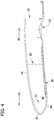
- FIGs 3 and 4 are schematic illustrations of nacelle assembly 12.
- nacelle assembly 12 is generally annular and defines an opening 32 sized and configured to channel air through nacelle assembly 12.
- Nacelle assembly 12 has a diameter 34 at forward end 33 measured with respect to an inner surface 43 that is smaller than a maximum diameter 36 of an outer surface of nacelle assembly 12.
- Nacelle assembly 12 includes an inner barrel 38 and an outer structure 40.
- outer structure 40 is fabricated from a continuous fiber reinforced thermoplastic material.
- outer structure 40 may be fabricated from a continuous fiber reinforced thermoset material.
- outer structure 40 incorporates an integral surfacing film to facilitate protecting nacelle assembly 12 from lighting strikes.
- Outer structure 40 includes a highlight 42 that is defined by forward end 33 of outer structure 40, an outer aft section 44 that is defined by highlight 42, and an inner aft section 46 that is defined by highlight 42.
- Outer aft section 44 includes a point 45 on an outer surface 47 defined by the maximum diameter 36 of nacelle assembly 12.
- outer structure 40 is coupled to a hoop frame (not shown) at an aft end 35 of outer aft section 44 proximate to a fan cowl 54, such that the hoop frame facilitates coupling outer structure 40 to fan cowl 54.
- inner aft section 46 includes a first flange 48 that is used to couple outer structure 40 to inner barrel 38.
- outer structure 40 includes a second flange 50 that is used to couple outer structure 40 to a fan case 53.
- nacelle assembly 12 includes a plurality of bulkheads 57, 58, and 59 that facilitate structurally supporting nacelle assembly 12.
- Bulkheads 57, 58, and 59 also facilitate absorbing any aftward forces induced to outer surface 47 of outer structure 40, such as may be created during a bird-strike for example.
- bulkhead 57 is coupled to outer aft section 44 and inner aft section 46
- bulkhead 58 is coupled to outer aft section 44 and inner barrel 38
- bulkhead 59 is coupled to outer aft section 44 and fan case 53.
- bulkhead 59 is coupled to an aft end 35 of outer aft section 44 such that bulkhead 59 facilitates coupling outer structure 40 to fan cowl 54.
- Bulkheads 57, 58, and 59 may be coupled through a plurality of coupling processes such as through a mechanical fastening process, a thermoplastic welding process, and an adhesive bonding process.
- FIG. 5 is a schematic illustration of outer structure 40.
- outer structure 40 includes at least one stiffener 56 that is oriented either circumferentially and/or longitudinally to facilitate structurally supporting outer aft section 44.
- stiffener 56 is an independent component that is coupled to inner surface 43 of outer structure 40 via, for example, thermoplastic welding and/or an adhesive bonding.
- stiffener 56 may be formed integrally with outer structure 40.
- nacelle assembly 12 includes a structural foam 60 that is oriented and positioned to facilitate absorbing any aftward forces induced to outer surface 47 of outer structure 40, such as may be created during a bird-strike for example.
- structural foam 60 is coupled downstream 35 from highlight 42, against inner surface 43 of outer structure 40 using at least one of a thermoplastic welding process and an adhesive bonding process.
- Outer structure 40 defines an aerodynamic surface over outer surface 47 and facilitates maintaining laminar flow over outer surface 47 from highlight 42 to point 45 defined by maximum diameter 36. Outer surface 47 facilitates reducing drag and improving aerodynamics and fuel efficiency. Moreover, outer structure 40 facilitates reducing assembly time and a number of components of nacelle assembly 12 as compared to known nacelle assemblies, thereby facilitating reducing manufacturing costs and improving manufacturing cycle time. The part count reduction and the use of advanced materials, such as thermoplastic or graphite, facilitate a weight reduction for nacelle assembly 12 as compared to known nacelle assemblies.
- the methods, apparatus, and systems described herein for an integrated inlet design are not limited to the specific embodiments described herein.
- the integrated inlet design described herein provides a more aerodynamic design that facilitates reducing drag and increasing fuel efficiency.
- Practice of the methods, apparatus, or systems described or illustrated herein is not limited to nacelle assemblies. Rather, the methods, apparatus, and systems described or illustrated herein may be utilized independently and separately from other components and/or steps described herein.
Landscapes
- Engineering & Computer Science (AREA)
- Chemical & Material Sciences (AREA)
- Combustion & Propulsion (AREA)
- Aviation & Aerospace Engineering (AREA)
- Mechanical Engineering (AREA)
- General Engineering & Computer Science (AREA)
- Wind Motors (AREA)
- Structures Of Non-Positive Displacement Pumps (AREA)
Claims (10)
- Verfahren zum Zusammenbauen einer Gondelbaugruppe (12), wobei das Verfahren umfasst:Bereitstellen einer äußeren Struktur (40), die sich wenigstens zwischen einer Triebwerkeintrittsfläche (42), die durch ein vorderes Ende (33) der äußeren Struktur (40) definiert ist, und einem Punkt (45), der durch einen maximalen Durchmesser (36) der Gondelbaugruppe (12) definiert ist, erstreckt;Koppeln eines Integralschaumstoffs (60) mit einer inneren Oberfläche eines äußeren hinteren Bereichs (44) der äußeren Struktur (40), wobei der Integralschaumstoff ausgerichtet und positioniert ist, um ein Aufnehmen von nach hinten gerichteten Kräften, die auf eine äußere Oberfläche (47) der äußere Struktur (40) induziert werden, zu erleichtern;Koppeln der äußeren Struktur (40) mit einem inneren Zylinder (38) und einem Fangehäuse (53);Bereitstellen eines Versteifungsteils (56), das mit der inneren Oberfläche des äußeren hinteren Bereichs (44) gekoppelt ist, wobei das Versteifungsteil (56) entweder in Umfangsrichtung und/oder in Längsrichtung ausgerichtet ist, um ein strukturelles Stützen des äußeren hinteren Bereichs (44) zu erleichtern;Bereitstellen einer ersten Trennwand (58), die mit dem äußeren hinteren Bereich (44) und dem inneren Zylinder (38) gekoppelt ist und sich zwischen diesen erstreckt;Bereitstellen einer zweiten Trennwand (57), die mit dem äußeren hinteren Bereich (44) und einem inneren hinteren Bereich (46) der äußeren Struktur (40) gekoppelt ist und sich zwischen diesen erstreckt; undBereitstellen einer dritten Trennwand (59), die mit dem äußeren hinteren Bereich (44) und dem Fangehäuse (53) gekoppelt ist und sich zwischen diesen erstreckt,wobei die erste, die zweite und die dritte Trennwand (57, 58, 59) konfiguriert sind, um das Aufnehmen von nach hinten gerichteten Kräften, die auf die äußere Oberfläche (47) der äußeren Struktur (40) induziert werden, zu erleichtern.
- Verfahren zum Zusammenbauen einer Gondelbaugruppe (12) nach Anspruch 1, wobei die äußere Struktur (40) aus einem faserverstärkten thermoplastischen Endlosmaterial und/oder einem faserverstärkten Duroplastendlosmaterial hergestellt ist.
- Verfahren zum Zusammenbauen einer Gondelbaugruppe (12) nach Anspruch 1, wobei die äußere Struktur (40) einen ersten Flansch (48) beinhaltet, der an einem inneren hinteren Bereich der äußeren Struktur (40) positioniert ist, wobei der erste Flansch (48) konfiguriert ist, um die äußere Struktur (40) mit dem inneren Zylinder (38) zu koppeln.
- Verfahren zum Zusammenbauen einer Gondelbaugruppe (12) nach Anspruch 1, wobei die äußere Struktur (40) einen zweiten Flansch (50) beinhaltet, der an einem inneren hinteren Bereich der äußeren Struktur (40) positioniert ist, wobei der zweite Flansch (50) konfiguriert ist, um die äußere Struktur (40) mit dem Fangehäuse (53) zu koppeln.
- Verfahren zum Zusammenbauen einer Gondelbaugruppe (12) nach Anspruch 1, wobei
das Versteifungsteil (56) und/oder die Trennwände (57, 58, 59) mit einer inneren Oberfläche des äußeren hinteren Bereichs (44) mittels thermoplastischem Schweißen und/oder Kleben gekoppelt ist. - Gondelbaugruppe (12), die einen inneren Zylinder (38), ein Fangehäuse (53) und eine äußere Struktur (40) umfasst, wobei die äußere Struktur (40) mit dem inneren Zylinder (38) und dem Fangehäuse (53) gekoppelt ist, wobei die äußere Struktur (40) umfasst:eine Triebwerkeintrittsfläche (42), die durch ein vorderes Ende der äußeren Struktur (40) definiert ist; undeinen äußeren hinteren Bereich (44), der einen Punkt (45), der durch einen maximalen Durchmesser (36) der Gondelbaugruppe (12) definiert ist, beinhaltet, wobei sich die Gondelbaugruppe (12) wenigstens zwischen der Triebwerkeintrittsfläche (42) und dem Punkt (45) erstreckt;einen Integralschaumstoff (60), der mit einer inneren Oberfläche des äußeren hinteren Bereichs (44) gekoppelt ist, wobei der Integralschaumstoff (60) ausgerichtet und positioniert ist, um das Aufnehmen beliebiger nach hinten gerichteter Kräfte, die auf die äußere Oberfläche (47) der äußeren Struktur (40) induziert werden, zu erleichtern;dadurch gekennzeichnet, dass die äußere Struktur (40) ferner umfasst:ein Versteifungsteil (56), das mit der inneren Oberfläche des äußeren hinteren Bereichs (44) gekoppelt ist, wobei das Versteifungsteil (56) entweder in Umfangsrichtung und/oder in Längsrichtung ausgerichtet ist, um das strukturelle Stützen des äußeren hinteren Bereichs (44) zu erleichtern;eine erste Trennwand (58), die mit dem äußeren hinteren Bereich (44) und dem inneren Zylinder (38) gekoppelt ist und sich zwischen diesen erstreckt;eine zweite Trennwand (57), die mit dem äußeren hinteren Bereich (44) und einem inneren hinteren Bereich (46) der äußeren Struktur (40) gekoppelt ist und sich zwischen diesen erstreckt; undeine dritte Trennwand (59), die mit dem äußeren hinteren Bereich (44) und dem Fangehäuse (53) gekoppelt ist und sich zwischen diesen erstreckt,wobei die erste, die zweite und die dritte Trennwand (57, 58, 59) konfiguriert sind, um das Aufnehmen beliebiger nach hinten gerichteter Kräfte, die auf die äußere Oberfläche (47) der äußeren Struktur (40) induziert werden, zu erleichtern.
- Gondelbaugruppe (12) nach Anspruch 6, wobei die äußere Struktur (40) aus einem faserverstärkten thermoplastischen Endlosmaterial und/oder einem faserverstärkten Duroplastendlosmaterial hergestellt ist.
- Gondelbaugruppe (12) nach Anspruch 6, die ferner einen ersten Flansch (48) umfasst, der an einem inneren hinteren Bereich (46) der äußeren Struktur (40) positioniert ist, wobei der erste Flansch (48) konfiguriert ist, um die äußere Struktur (40) mit dem inneren Zylinder (38) zu koppeln.
- Gondelbaugruppe (12) nach Anspruch 6, die ferner einen zweiten Flansch (50) umfasst, der an einem inneren hinteren Bereich (46) der äußeren Struktur (40) positioniert ist, wobei der zweite Flansch (50) konfiguriert ist, um die äußere Struktur (40) mit dem Fangehäuse (53) zu koppeln.
- Gondelbaugruppe (12) nach Anspruch 6, wobei das Versteifungsteil (56) und/oder die Trennwände (57, 58, 59) mit einer inneren Oberfläche des äußeren hinteren Bereichs (44) mittels thermoplastischem Schweißen und/oder Kleben gekoppelt ist.
Applications Claiming Priority (2)
| Application Number | Priority Date | Filing Date | Title |
|---|---|---|---|
| US12/274,038 US8152461B2 (en) | 2008-11-19 | 2008-11-19 | Integrated inlet design |
| PCT/US2009/059996 WO2010059301A2 (en) | 2008-11-19 | 2009-10-08 | Integrated inlet design |
Publications (2)
| Publication Number | Publication Date |
|---|---|
| EP2346736A2 EP2346736A2 (de) | 2011-07-27 |
| EP2346736B1 true EP2346736B1 (de) | 2020-11-25 |
Family
ID=42172193
Family Applications (1)
| Application Number | Title | Priority Date | Filing Date |
|---|---|---|---|
| EP09741092.2A Active EP2346736B1 (de) | 2008-11-19 | 2009-10-08 | Integrierte einlassausführung |
Country Status (5)
| Country | Link |
|---|---|
| US (1) | US8152461B2 (de) |
| EP (1) | EP2346736B1 (de) |
| JP (1) | JP2012509440A (de) |
| CA (1) | CA2742834C (de) |
| WO (1) | WO2010059301A2 (de) |
Families Citing this family (17)
| Publication number | Priority date | Publication date | Assignee | Title |
|---|---|---|---|---|
| US8197191B2 (en) * | 2009-04-14 | 2012-06-12 | Rohr, Inc. | Inlet section of an aircraft engine nacelle |
| US8382039B2 (en) * | 2009-12-30 | 2013-02-26 | MRA Systems Inc. | Turbomachine nacelle and anti-icing system and method therefor |
| GB201202790D0 (en) * | 2012-02-20 | 2012-04-04 | Rolls Royce Plc | An aircraft propulsion system |
| US9168716B2 (en) * | 2012-09-14 | 2015-10-27 | The Boeing Company | Metallic sandwich structure having small bend radius |
| FR2987601A1 (fr) * | 2012-09-20 | 2013-09-06 | Aircelle Sa | Nacelle laminaire |
| US20140186166A1 (en) * | 2012-12-27 | 2014-07-03 | General Electric Company | Hybrid Continuous Fiber Chopped Fiber Polymer Composite Structure |
| ITFI20130100A1 (it) * | 2013-05-03 | 2014-11-04 | Nuovo Pignone Srl | "composite material inlet plenum and gas turbine engine system comprising said plenum" |
| US9664113B2 (en) * | 2014-03-15 | 2017-05-30 | The Boeing Company | One piece inlet lip skin design |
| US9725190B2 (en) * | 2015-02-13 | 2017-08-08 | The Boeing Company | Aircraft engine inlet assembly apparatus |
| US10160552B2 (en) | 2016-02-12 | 2018-12-25 | Rohr, Inc. | Inlet assembly for a turbofan engine |
| US11125157B2 (en) * | 2017-09-22 | 2021-09-21 | The Boeing Company | Advanced inlet design |
| FR3075761A1 (fr) * | 2017-12-21 | 2019-06-28 | Airbus Operations | Partie anterieure de nacelle d'un ensemble propulsif comportant un cadre de rigidification incline |
| US11946413B2 (en) * | 2019-07-29 | 2024-04-02 | The Boeing Company | Inlet bulkheads for large diameter aircraft engines |
| FR3099915A1 (fr) * | 2019-08-13 | 2021-02-19 | Airbus Operations | Partie antérieure de nacelle d’un ensemble propulsif d’aéronef dont la lèvre d’entrée d’air est liée au panneau extérieur par emboitement |
| EP3945033B1 (de) * | 2020-07-27 | 2022-09-07 | Airbus Operations (S.A.S.) | Flugzeugantriebseinheit |
| FR3115223B1 (fr) * | 2020-10-21 | 2023-05-12 | Safran Nacelles | Fabrication d’une lèvre d’entrée d’air ou d’un secteur annulaire de lèvre d’entrée d’air intégrant des ouvertures à bord rentré |
| BR102022003769A2 (pt) | 2021-05-04 | 2022-11-16 | The Boeing Company | Estrutura de entrada de nacele de um conjunto de motor |
Family Cites Families (14)
| Publication number | Priority date | Publication date | Assignee | Title |
|---|---|---|---|---|
| US3871844A (en) * | 1973-09-28 | 1975-03-18 | Sr Frank F Calvin | Screen apparatus for air inlet |
| US5259724A (en) * | 1992-05-01 | 1993-11-09 | General Electric Company | Inlet fan blade fragment containment shield |
| FR2757823B1 (fr) * | 1996-12-26 | 1999-03-12 | Aerospatiale | Nacelle de turboreacteur a ecoulement laminaire |
| US5931422A (en) * | 1997-06-09 | 1999-08-03 | Mcdonnell Douglas | Active reinforced elastomer system |
| US6089505A (en) * | 1997-07-22 | 2000-07-18 | Mcdonnell Douglas Corporation | Mission adaptive inlet |
| GB9921935D0 (en) | 1999-09-17 | 1999-11-17 | Rolls Royce | A nacelle assembly for a gas turbine engine |
| US7588212B2 (en) * | 2003-07-08 | 2009-09-15 | Rohr Inc. | Method and apparatus for noise abatement and ice protection of an aircraft engine nacelle inlet lip |
| US7370467B2 (en) * | 2003-07-29 | 2008-05-13 | Pratt & Whitney Canada Corp. | Turbofan case and method of making |
| EP1777378A3 (de) * | 2003-07-29 | 2011-03-09 | Pratt & Whitney Canada Corp. | Gehäuse für ein Mantelstromtriebwerk und Herstellungsverfahren dafür |
| FR2868123B1 (fr) * | 2004-03-29 | 2006-06-23 | Airbus France Sas | Structure d'entree d'air pour moteur d'aeronef |
| US20060032983A1 (en) * | 2004-07-19 | 2006-02-16 | Brand Joseph H | Foreign object damage tolerant nacelle anti-icing system |
| US7923668B2 (en) * | 2006-02-24 | 2011-04-12 | Rohr, Inc. | Acoustic nacelle inlet lip having composite construction and an integral electric ice protection heater disposed therein |
| FR2906568B1 (fr) | 2006-10-02 | 2012-01-06 | Aircelle Sa | Structure d'entree d'air deposable pour nacelle de turboreacteur. |
| US8092169B2 (en) * | 2008-09-16 | 2012-01-10 | United Technologies Corporation | Integrated inlet fan case |
-
2008
- 2008-11-19 US US12/274,038 patent/US8152461B2/en active Active
-
2009
- 2009-10-08 WO PCT/US2009/059996 patent/WO2010059301A2/en not_active Ceased
- 2009-10-08 EP EP09741092.2A patent/EP2346736B1/de active Active
- 2009-10-08 JP JP2011537450A patent/JP2012509440A/ja active Pending
- 2009-10-08 CA CA2742834A patent/CA2742834C/en active Active
Non-Patent Citations (1)
| Title |
|---|
| None * |
Also Published As
| Publication number | Publication date |
|---|---|
| JP2012509440A (ja) | 2012-04-19 |
| CA2742834A1 (en) | 2010-05-27 |
| EP2346736A2 (de) | 2011-07-27 |
| WO2010059301A3 (en) | 2010-07-22 |
| WO2010059301A2 (en) | 2010-05-27 |
| US20100124494A1 (en) | 2010-05-20 |
| CA2742834C (en) | 2017-03-28 |
| US8152461B2 (en) | 2012-04-10 |
Similar Documents
| Publication | Publication Date | Title |
|---|---|---|
| EP2346736B1 (de) | Integrierte einlassausführung | |
| US10160552B2 (en) | Inlet assembly for a turbofan engine | |
| US9194330B2 (en) | Retrofitable auxiliary inlet scoop | |
| EP1942253A2 (de) | Leitschaufel und Herstellungsverfahren dafür | |
| US9103298B2 (en) | Seal for a variable area fan nozzle | |
| US20080159856A1 (en) | Guide vane and method of fabricating the same | |
| US9745851B2 (en) | Metal leading edge on composite blade airfoil and shank | |
| CA2752272C (en) | Rotor assembly | |
| US20180334249A1 (en) | Strake for aircraft propulsion system nacelle | |
| EP2971660B1 (de) | Thermische anpassung einer schallauskleidungskartusche für einen gasturbinenmotor | |
| US12018592B1 (en) | Outlet guide vane assembly for a turbofan engine | |
| CN110778370B (zh) | 机舱入口唇部熔断结构 | |
| US10502161B2 (en) | Cascade system and apparatus | |
| EP3628589B1 (de) | Strukturelle sammelkammerstütze für aktive laminarströmungssteuerung | |
| US11548652B2 (en) | Nacelle | |
| US12276199B2 (en) | Outlet guide vane assembly for a turbofan engine | |
| US9856742B2 (en) | Sealing system for variable area fan nozzle | |
| US10767596B2 (en) | Nacelle |
Legal Events
| Date | Code | Title | Description |
|---|---|---|---|
| PUAI | Public reference made under article 153(3) epc to a published international application that has entered the european phase |
Free format text: ORIGINAL CODE: 0009012 |
|
| 17P | Request for examination filed |
Effective date: 20110620 |
|
| AK | Designated contracting states |
Kind code of ref document: A2 Designated state(s): AT BE BG CH CY CZ DE DK EE ES FI FR GB GR HR HU IE IS IT LI LT LU LV MC MK MT NL NO PL PT RO SE SI SK SM TR |
|
| AX | Request for extension of the european patent |
Extension state: AL BA RS |
|
| DAX | Request for extension of the european patent (deleted) | ||
| STAA | Information on the status of an ep patent application or granted ep patent |
Free format text: STATUS: EXAMINATION IS IN PROGRESS |
|
| 17Q | First examination report despatched |
Effective date: 20180712 |
|
| GRAP | Despatch of communication of intention to grant a patent |
Free format text: ORIGINAL CODE: EPIDOSNIGR1 |
|
| STAA | Information on the status of an ep patent application or granted ep patent |
Free format text: STATUS: GRANT OF PATENT IS INTENDED |
|
| INTG | Intention to grant announced |
Effective date: 20200214 |
|
| GRAJ | Information related to disapproval of communication of intention to grant by the applicant or resumption of examination proceedings by the epo deleted |
Free format text: ORIGINAL CODE: EPIDOSDIGR1 |
|
| STAA | Information on the status of an ep patent application or granted ep patent |
Free format text: STATUS: EXAMINATION IS IN PROGRESS |
|
| GRAP | Despatch of communication of intention to grant a patent |
Free format text: ORIGINAL CODE: EPIDOSNIGR1 |
|
| STAA | Information on the status of an ep patent application or granted ep patent |
Free format text: STATUS: GRANT OF PATENT IS INTENDED |
|
| INTC | Intention to grant announced (deleted) | ||
| INTG | Intention to grant announced |
Effective date: 20200623 |
|
| GRAS | Grant fee paid |
Free format text: ORIGINAL CODE: EPIDOSNIGR3 |
|
| GRAA | (expected) grant |
Free format text: ORIGINAL CODE: 0009210 |
|
| STAA | Information on the status of an ep patent application or granted ep patent |
Free format text: STATUS: THE PATENT HAS BEEN GRANTED |
|
| AK | Designated contracting states |
Kind code of ref document: B1 Designated state(s): AT BE BG CH CY CZ DE DK EE ES FI FR GB GR HR HU IE IS IT LI LT LU LV MC MK MT NL NO PL PT RO SE SI SK SM TR |
|
| REG | Reference to a national code |
Ref country code: GB Ref legal event code: FG4D |
|
| REG | Reference to a national code |
Ref country code: CH Ref legal event code: EP |
|
| REG | Reference to a national code |
Ref country code: DE Ref legal event code: R096 Ref document number: 602009063096 Country of ref document: DE |
|
| REG | Reference to a national code |
Ref country code: AT Ref legal event code: REF Ref document number: 1338011 Country of ref document: AT Kind code of ref document: T Effective date: 20201215 |
|
| REG | Reference to a national code |
Ref country code: IE Ref legal event code: FG4D |
|
| REG | Reference to a national code |
Ref country code: AT Ref legal event code: MK05 Ref document number: 1338011 Country of ref document: AT Kind code of ref document: T Effective date: 20201125 |
|
| REG | Reference to a national code |
Ref country code: NL Ref legal event code: MP Effective date: 20201125 |
|
| PG25 | Lapsed in a contracting state [announced via postgrant information from national office to epo] |
Ref country code: GR Free format text: LAPSE BECAUSE OF FAILURE TO SUBMIT A TRANSLATION OF THE DESCRIPTION OR TO PAY THE FEE WITHIN THE PRESCRIBED TIME-LIMIT Effective date: 20210226 Ref country code: NO Free format text: LAPSE BECAUSE OF FAILURE TO SUBMIT A TRANSLATION OF THE DESCRIPTION OR TO PAY THE FEE WITHIN THE PRESCRIBED TIME-LIMIT Effective date: 20210225 Ref country code: PT Free format text: LAPSE BECAUSE OF FAILURE TO SUBMIT A TRANSLATION OF THE DESCRIPTION OR TO PAY THE FEE WITHIN THE PRESCRIBED TIME-LIMIT Effective date: 20210325 Ref country code: FI Free format text: LAPSE BECAUSE OF FAILURE TO SUBMIT A TRANSLATION OF THE DESCRIPTION OR TO PAY THE FEE WITHIN THE PRESCRIBED TIME-LIMIT Effective date: 20201125 |
|
| PG25 | Lapsed in a contracting state [announced via postgrant information from national office to epo] |
Ref country code: AT Free format text: LAPSE BECAUSE OF FAILURE TO SUBMIT A TRANSLATION OF THE DESCRIPTION OR TO PAY THE FEE WITHIN THE PRESCRIBED TIME-LIMIT Effective date: 20201125 Ref country code: BG Free format text: LAPSE BECAUSE OF FAILURE TO SUBMIT A TRANSLATION OF THE DESCRIPTION OR TO PAY THE FEE WITHIN THE PRESCRIBED TIME-LIMIT Effective date: 20210225 Ref country code: IS Free format text: LAPSE BECAUSE OF FAILURE TO SUBMIT A TRANSLATION OF THE DESCRIPTION OR TO PAY THE FEE WITHIN THE PRESCRIBED TIME-LIMIT Effective date: 20210325 Ref country code: SE Free format text: LAPSE BECAUSE OF FAILURE TO SUBMIT A TRANSLATION OF THE DESCRIPTION OR TO PAY THE FEE WITHIN THE PRESCRIBED TIME-LIMIT Effective date: 20201125 Ref country code: PL Free format text: LAPSE BECAUSE OF FAILURE TO SUBMIT A TRANSLATION OF THE DESCRIPTION OR TO PAY THE FEE WITHIN THE PRESCRIBED TIME-LIMIT Effective date: 20201125 Ref country code: LV Free format text: LAPSE BECAUSE OF FAILURE TO SUBMIT A TRANSLATION OF THE DESCRIPTION OR TO PAY THE FEE WITHIN THE PRESCRIBED TIME-LIMIT Effective date: 20201125 |
|
| REG | Reference to a national code |
Ref country code: LT Ref legal event code: MG9D |
|
| PG25 | Lapsed in a contracting state [announced via postgrant information from national office to epo] |
Ref country code: HR Free format text: LAPSE BECAUSE OF FAILURE TO SUBMIT A TRANSLATION OF THE DESCRIPTION OR TO PAY THE FEE WITHIN THE PRESCRIBED TIME-LIMIT Effective date: 20201125 |
|
| PG25 | Lapsed in a contracting state [announced via postgrant information from national office to epo] |
Ref country code: LT Free format text: LAPSE BECAUSE OF FAILURE TO SUBMIT A TRANSLATION OF THE DESCRIPTION OR TO PAY THE FEE WITHIN THE PRESCRIBED TIME-LIMIT Effective date: 20201125 Ref country code: EE Free format text: LAPSE BECAUSE OF FAILURE TO SUBMIT A TRANSLATION OF THE DESCRIPTION OR TO PAY THE FEE WITHIN THE PRESCRIBED TIME-LIMIT Effective date: 20201125 Ref country code: CZ Free format text: LAPSE BECAUSE OF FAILURE TO SUBMIT A TRANSLATION OF THE DESCRIPTION OR TO PAY THE FEE WITHIN THE PRESCRIBED TIME-LIMIT Effective date: 20201125 Ref country code: RO Free format text: LAPSE BECAUSE OF FAILURE TO SUBMIT A TRANSLATION OF THE DESCRIPTION OR TO PAY THE FEE WITHIN THE PRESCRIBED TIME-LIMIT Effective date: 20201125 Ref country code: SK Free format text: LAPSE BECAUSE OF FAILURE TO SUBMIT A TRANSLATION OF THE DESCRIPTION OR TO PAY THE FEE WITHIN THE PRESCRIBED TIME-LIMIT Effective date: 20201125 Ref country code: SM Free format text: LAPSE BECAUSE OF FAILURE TO SUBMIT A TRANSLATION OF THE DESCRIPTION OR TO PAY THE FEE WITHIN THE PRESCRIBED TIME-LIMIT Effective date: 20201125 |
|
| REG | Reference to a national code |
Ref country code: DE Ref legal event code: R097 Ref document number: 602009063096 Country of ref document: DE |
|
| PG25 | Lapsed in a contracting state [announced via postgrant information from national office to epo] |
Ref country code: DK Free format text: LAPSE BECAUSE OF FAILURE TO SUBMIT A TRANSLATION OF THE DESCRIPTION OR TO PAY THE FEE WITHIN THE PRESCRIBED TIME-LIMIT Effective date: 20201125 |
|
| PLBE | No opposition filed within time limit |
Free format text: ORIGINAL CODE: 0009261 |
|
| STAA | Information on the status of an ep patent application or granted ep patent |
Free format text: STATUS: NO OPPOSITION FILED WITHIN TIME LIMIT |
|
| PG25 | Lapsed in a contracting state [announced via postgrant information from national office to epo] |
Ref country code: NL Free format text: LAPSE BECAUSE OF FAILURE TO SUBMIT A TRANSLATION OF THE DESCRIPTION OR TO PAY THE FEE WITHIN THE PRESCRIBED TIME-LIMIT Effective date: 20201125 Ref country code: IT Free format text: LAPSE BECAUSE OF FAILURE TO SUBMIT A TRANSLATION OF THE DESCRIPTION OR TO PAY THE FEE WITHIN THE PRESCRIBED TIME-LIMIT Effective date: 20201125 |
|
| 26N | No opposition filed |
Effective date: 20210826 |
|
| PG25 | Lapsed in a contracting state [announced via postgrant information from national office to epo] |
Ref country code: ES Free format text: LAPSE BECAUSE OF FAILURE TO SUBMIT A TRANSLATION OF THE DESCRIPTION OR TO PAY THE FEE WITHIN THE PRESCRIBED TIME-LIMIT Effective date: 20201125 Ref country code: SI Free format text: LAPSE BECAUSE OF FAILURE TO SUBMIT A TRANSLATION OF THE DESCRIPTION OR TO PAY THE FEE WITHIN THE PRESCRIBED TIME-LIMIT Effective date: 20201125 |
|
| REG | Reference to a national code |
Ref country code: DE Ref legal event code: R119 Ref document number: 602009063096 Country of ref document: DE |
|
| REG | Reference to a national code |
Ref country code: CH Ref legal event code: PL |
|
| PG25 | Lapsed in a contracting state [announced via postgrant information from national office to epo] |
Ref country code: IS Free format text: LAPSE BECAUSE OF FAILURE TO SUBMIT A TRANSLATION OF THE DESCRIPTION OR TO PAY THE FEE WITHIN THE PRESCRIBED TIME-LIMIT Effective date: 20210325 |
|
| REG | Reference to a national code |
Ref country code: BE Ref legal event code: MM Effective date: 20211031 |
|
| GBPC | Gb: european patent ceased through non-payment of renewal fee |
Effective date: 20211008 |
|
| PG25 | Lapsed in a contracting state [announced via postgrant information from national office to epo] |
Ref country code: MC Free format text: LAPSE BECAUSE OF FAILURE TO SUBMIT A TRANSLATION OF THE DESCRIPTION OR TO PAY THE FEE WITHIN THE PRESCRIBED TIME-LIMIT Effective date: 20201125 |
|
| PG25 | Lapsed in a contracting state [announced via postgrant information from national office to epo] |
Ref country code: LU Free format text: LAPSE BECAUSE OF NON-PAYMENT OF DUE FEES Effective date: 20211008 Ref country code: GB Free format text: LAPSE BECAUSE OF NON-PAYMENT OF DUE FEES Effective date: 20211008 Ref country code: DE Free format text: LAPSE BECAUSE OF NON-PAYMENT OF DUE FEES Effective date: 20220503 Ref country code: BE Free format text: LAPSE BECAUSE OF NON-PAYMENT OF DUE FEES Effective date: 20211031 |
|
| PG25 | Lapsed in a contracting state [announced via postgrant information from national office to epo] |
Ref country code: LI Free format text: LAPSE BECAUSE OF NON-PAYMENT OF DUE FEES Effective date: 20211031 Ref country code: CH Free format text: LAPSE BECAUSE OF NON-PAYMENT OF DUE FEES Effective date: 20211031 |
|
| PG25 | Lapsed in a contracting state [announced via postgrant information from national office to epo] |
Ref country code: IE Free format text: LAPSE BECAUSE OF NON-PAYMENT OF DUE FEES Effective date: 20211008 |
|
| PG25 | Lapsed in a contracting state [announced via postgrant information from national office to epo] |
Ref country code: HU Free format text: LAPSE BECAUSE OF FAILURE TO SUBMIT A TRANSLATION OF THE DESCRIPTION OR TO PAY THE FEE WITHIN THE PRESCRIBED TIME-LIMIT; INVALID AB INITIO Effective date: 20091008 Ref country code: CY Free format text: LAPSE BECAUSE OF FAILURE TO SUBMIT A TRANSLATION OF THE DESCRIPTION OR TO PAY THE FEE WITHIN THE PRESCRIBED TIME-LIMIT Effective date: 20201125 |
|
| PG25 | Lapsed in a contracting state [announced via postgrant information from national office to epo] |
Ref country code: MK Free format text: LAPSE BECAUSE OF FAILURE TO SUBMIT A TRANSLATION OF THE DESCRIPTION OR TO PAY THE FEE WITHIN THE PRESCRIBED TIME-LIMIT Effective date: 20201125 |
|
| PG25 | Lapsed in a contracting state [announced via postgrant information from national office to epo] |
Ref country code: TR Free format text: LAPSE BECAUSE OF FAILURE TO SUBMIT A TRANSLATION OF THE DESCRIPTION OR TO PAY THE FEE WITHIN THE PRESCRIBED TIME-LIMIT Effective date: 20201125 |
|
| PG25 | Lapsed in a contracting state [announced via postgrant information from national office to epo] |
Ref country code: MT Free format text: LAPSE BECAUSE OF FAILURE TO SUBMIT A TRANSLATION OF THE DESCRIPTION OR TO PAY THE FEE WITHIN THE PRESCRIBED TIME-LIMIT Effective date: 20201125 |
|
| PGFP | Annual fee paid to national office [announced via postgrant information from national office to epo] |
Ref country code: FR Payment date: 20250923 Year of fee payment: 17 |