EP2347487B1 - Containeranordnung - Google Patents
Containeranordnung Download PDFInfo
- Publication number
- EP2347487B1 EP2347487B1 EP09745095.1A EP09745095A EP2347487B1 EP 2347487 B1 EP2347487 B1 EP 2347487B1 EP 09745095 A EP09745095 A EP 09745095A EP 2347487 B1 EP2347487 B1 EP 2347487B1
- Authority
- EP
- European Patent Office
- Prior art keywords
- container
- lid
- catch
- type
- port
- Prior art date
- Legal status (The legal status is an assumption and is not a legal conclusion. Google has not performed a legal analysis and makes no representation as to the accuracy of the status listed.)
- Active
Links
Images




Classifications
-
- H—ELECTRICITY
- H02—GENERATION; CONVERSION OR DISTRIBUTION OF ELECTRIC POWER
- H02G—INSTALLATION OF ELECTRIC CABLES OR LINES, OR OF COMBINED OPTICAL AND ELECTRIC CABLES OR LINES
- H02G3/00—Installations of electric cables or lines or protective tubing therefor in or on buildings, equivalent structures or vehicles
- H02G3/02—Details
- H02G3/08—Distribution boxes; Connection or junction boxes
- H02G3/088—Dustproof, splashproof, drip-proof, waterproof, or flameproof casings or inlets
-
- H—ELECTRICITY
- H01—ELECTRIC ELEMENTS
- H01R—ELECTRICALLY-CONDUCTIVE CONNECTIONS; STRUCTURAL ASSOCIATIONS OF A PLURALITY OF MUTUALLY-INSULATED ELECTRICAL CONNECTING ELEMENTS; COUPLING DEVICES; CURRENT COLLECTORS
- H01R13/00—Details of coupling devices of the kinds covered by groups H01R12/70 or H01R24/00 - H01R33/00
- H01R13/46—Bases; Cases
- H01R13/502—Bases; Cases composed of different pieces
- H01R13/508—Bases; Cases composed of different pieces assembled by a separate clip or spring
-
- B—PERFORMING OPERATIONS; TRANSPORTING
- B65—CONVEYING; PACKING; STORING; HANDLING THIN OR FILAMENTARY MATERIAL
- B65D—CONTAINERS FOR STORAGE OR TRANSPORT OF ARTICLES OR MATERIALS, e.g. BAGS, BARRELS, BOTTLES, BOXES, CANS, CARTONS, CRATES, DRUMS, JARS, TANKS, HOPPERS, FORWARDING CONTAINERS; ACCESSORIES, CLOSURES, OR FITTINGS THEREFOR; PACKAGING ELEMENTS; PACKAGES
- B65D43/00—Lids or covers for rigid or semi-rigid containers
- B65D43/02—Removable lids or covers
- B65D43/0202—Removable lids or covers without integral tamper element
- B65D43/0204—Removable lids or covers without integral tamper element secured by snapping over beads or projections
- B65D43/0212—Removable lids or covers without integral tamper element secured by snapping over beads or projections only on the outside, or a part turned to the outside, of the mouth
-
- H—ELECTRICITY
- H02—GENERATION; CONVERSION OR DISTRIBUTION OF ELECTRIC POWER
- H02G—INSTALLATION OF ELECTRIC CABLES OR LINES, OR OF COMBINED OPTICAL AND ELECTRIC CABLES OR LINES
- H02G3/00—Installations of electric cables or lines or protective tubing therefor in or on buildings, equivalent structures or vehicles
- H02G3/02—Details
- H02G3/08—Distribution boxes; Connection or junction boxes
- H02G3/14—Fastening of cover or lid to box
-
- B—PERFORMING OPERATIONS; TRANSPORTING
- B65—CONVEYING; PACKING; STORING; HANDLING THIN OR FILAMENTARY MATERIAL
- B65D—CONTAINERS FOR STORAGE OR TRANSPORT OF ARTICLES OR MATERIALS, e.g. BAGS, BARRELS, BOTTLES, BOXES, CANS, CARTONS, CRATES, DRUMS, JARS, TANKS, HOPPERS, FORWARDING CONTAINERS; ACCESSORIES, CLOSURES, OR FITTINGS THEREFOR; PACKAGING ELEMENTS; PACKAGES
- B65D2543/00—Lids or covers essentially for box-like containers
- B65D2543/00009—Details of lids or covers for rigid or semi-rigid containers
- B65D2543/00018—Overall construction of the lid
- B65D2543/00064—Shape of the outer periphery
- B65D2543/00074—Shape of the outer periphery curved
- B65D2543/00101—Shape of the outer periphery curved square-like or rectangular-like
-
- B—PERFORMING OPERATIONS; TRANSPORTING
- B65—CONVEYING; PACKING; STORING; HANDLING THIN OR FILAMENTARY MATERIAL
- B65D—CONTAINERS FOR STORAGE OR TRANSPORT OF ARTICLES OR MATERIALS, e.g. BAGS, BARRELS, BOTTLES, BOXES, CANS, CARTONS, CRATES, DRUMS, JARS, TANKS, HOPPERS, FORWARDING CONTAINERS; ACCESSORIES, CLOSURES, OR FITTINGS THEREFOR; PACKAGING ELEMENTS; PACKAGES
- B65D2543/00—Lids or covers essentially for box-like containers
- B65D2543/00009—Details of lids or covers for rigid or semi-rigid containers
- B65D2543/00018—Overall construction of the lid
- B65D2543/00259—Materials used
- B65D2543/00296—Plastic
-
- B—PERFORMING OPERATIONS; TRANSPORTING
- B65—CONVEYING; PACKING; STORING; HANDLING THIN OR FILAMENTARY MATERIAL
- B65D—CONTAINERS FOR STORAGE OR TRANSPORT OF ARTICLES OR MATERIALS, e.g. BAGS, BARRELS, BOTTLES, BOXES, CANS, CARTONS, CRATES, DRUMS, JARS, TANKS, HOPPERS, FORWARDING CONTAINERS; ACCESSORIES, CLOSURES, OR FITTINGS THEREFOR; PACKAGING ELEMENTS; PACKAGES
- B65D2543/00—Lids or covers essentially for box-like containers
- B65D2543/00009—Details of lids or covers for rigid or semi-rigid containers
- B65D2543/00444—Contact between the container and the lid
- B65D2543/00481—Contact between the container and the lid on the inside or the outside of the container
- B65D2543/00537—Contact between the container and the lid on the inside or the outside of the container on the outside, or a part turned to the outside of the mouth of the container
-
- B—PERFORMING OPERATIONS; TRANSPORTING
- B65—CONVEYING; PACKING; STORING; HANDLING THIN OR FILAMENTARY MATERIAL
- B65D—CONTAINERS FOR STORAGE OR TRANSPORT OF ARTICLES OR MATERIALS, e.g. BAGS, BARRELS, BOTTLES, BOXES, CANS, CARTONS, CRATES, DRUMS, JARS, TANKS, HOPPERS, FORWARDING CONTAINERS; ACCESSORIES, CLOSURES, OR FITTINGS THEREFOR; PACKAGING ELEMENTS; PACKAGES
- B65D2543/00—Lids or covers essentially for box-like containers
- B65D2543/00009—Details of lids or covers for rigid or semi-rigid containers
- B65D2543/00444—Contact between the container and the lid
- B65D2543/00574—Contact between the container and the lid secured locally, i.e. a lot less than half the periphery
-
- B—PERFORMING OPERATIONS; TRANSPORTING
- B65—CONVEYING; PACKING; STORING; HANDLING THIN OR FILAMENTARY MATERIAL
- B65D—CONTAINERS FOR STORAGE OR TRANSPORT OF ARTICLES OR MATERIALS, e.g. BAGS, BARRELS, BOTTLES, BOXES, CANS, CARTONS, CRATES, DRUMS, JARS, TANKS, HOPPERS, FORWARDING CONTAINERS; ACCESSORIES, CLOSURES, OR FITTINGS THEREFOR; PACKAGING ELEMENTS; PACKAGES
- B65D2543/00—Lids or covers essentially for box-like containers
- B65D2543/00009—Details of lids or covers for rigid or semi-rigid containers
- B65D2543/00444—Contact between the container and the lid
- B65D2543/00592—Snapping means
- B65D2543/00601—Snapping means on the container
- B65D2543/00611—Profiles
- B65D2543/00648—Flange or lip
-
- B—PERFORMING OPERATIONS; TRANSPORTING
- B65—CONVEYING; PACKING; STORING; HANDLING THIN OR FILAMENTARY MATERIAL
- B65D—CONTAINERS FOR STORAGE OR TRANSPORT OF ARTICLES OR MATERIALS, e.g. BAGS, BARRELS, BOTTLES, BOXES, CANS, CARTONS, CRATES, DRUMS, JARS, TANKS, HOPPERS, FORWARDING CONTAINERS; ACCESSORIES, CLOSURES, OR FITTINGS THEREFOR; PACKAGING ELEMENTS; PACKAGES
- B65D2543/00—Lids or covers essentially for box-like containers
- B65D2543/00009—Details of lids or covers for rigid or semi-rigid containers
- B65D2543/00444—Contact between the container and the lid
- B65D2543/00592—Snapping means
- B65D2543/00601—Snapping means on the container
- B65D2543/00675—Periphery concerned
- B65D2543/00694—Segments
-
- B—PERFORMING OPERATIONS; TRANSPORTING
- B65—CONVEYING; PACKING; STORING; HANDLING THIN OR FILAMENTARY MATERIAL
- B65D—CONTAINERS FOR STORAGE OR TRANSPORT OF ARTICLES OR MATERIALS, e.g. BAGS, BARRELS, BOTTLES, BOXES, CANS, CARTONS, CRATES, DRUMS, JARS, TANKS, HOPPERS, FORWARDING CONTAINERS; ACCESSORIES, CLOSURES, OR FITTINGS THEREFOR; PACKAGING ELEMENTS; PACKAGES
- B65D2543/00—Lids or covers essentially for box-like containers
- B65D2543/00009—Details of lids or covers for rigid or semi-rigid containers
- B65D2543/00444—Contact between the container and the lid
- B65D2543/00592—Snapping means
- B65D2543/00712—Snapping means on the lid
- B65D2543/00722—Profiles
- B65D2543/0074—Massive bead
-
- B—PERFORMING OPERATIONS; TRANSPORTING
- B65—CONVEYING; PACKING; STORING; HANDLING THIN OR FILAMENTARY MATERIAL
- B65D—CONTAINERS FOR STORAGE OR TRANSPORT OF ARTICLES OR MATERIALS, e.g. BAGS, BARRELS, BOTTLES, BOXES, CANS, CARTONS, CRATES, DRUMS, JARS, TANKS, HOPPERS, FORWARDING CONTAINERS; ACCESSORIES, CLOSURES, OR FITTINGS THEREFOR; PACKAGING ELEMENTS; PACKAGES
- B65D2543/00—Lids or covers essentially for box-like containers
- B65D2543/00009—Details of lids or covers for rigid or semi-rigid containers
- B65D2543/00444—Contact between the container and the lid
- B65D2543/00592—Snapping means
- B65D2543/00712—Snapping means on the lid
- B65D2543/00787—Periphery concerned
- B65D2543/00805—Segments
-
- Y—GENERAL TAGGING OF NEW TECHNOLOGICAL DEVELOPMENTS; GENERAL TAGGING OF CROSS-SECTIONAL TECHNOLOGIES SPANNING OVER SEVERAL SECTIONS OF THE IPC; TECHNICAL SUBJECTS COVERED BY FORMER USPC CROSS-REFERENCE ART COLLECTIONS [XRACs] AND DIGESTS
- Y10—TECHNICAL SUBJECTS COVERED BY FORMER USPC
- Y10T—TECHNICAL SUBJECTS COVERED BY FORMER US CLASSIFICATION
- Y10T29/00—Metal working
- Y10T29/49—Method of mechanical manufacture
- Y10T29/49826—Assembling or joining
-
- Y—GENERAL TAGGING OF NEW TECHNOLOGICAL DEVELOPMENTS; GENERAL TAGGING OF CROSS-SECTIONAL TECHNOLOGIES SPANNING OVER SEVERAL SECTIONS OF THE IPC; TECHNICAL SUBJECTS COVERED BY FORMER USPC CROSS-REFERENCE ART COLLECTIONS [XRACs] AND DIGESTS
- Y10—TECHNICAL SUBJECTS COVERED BY FORMER USPC
- Y10T—TECHNICAL SUBJECTS COVERED BY FORMER US CLASSIFICATION
- Y10T29/00—Metal working
- Y10T29/49—Method of mechanical manufacture
- Y10T29/49826—Assembling or joining
- Y10T29/49904—Assembling a subassembly, then assembling with a second subassembly
Definitions
- the present invention relates to a container arrangement and to a method of connecting a container and lid to form a container arrangement.
- the present invention is particularly, although not exclusively, applicable to an outdoor container arrangement for housing electrical connections with cables extending into and out of the container through ports that can be sealed.
- US 2003/0000720 A1 shows an example of a container arrangement.
- GB1415242 discloses a container according to the preamble of claim 1 and a method according to the preamble of claim 11.
- EP 1 622 280 provides a cover body 3 that pivots on a casing body 2. To effect the seal locking wings 37a, b and c have to be pivoted such that locking holes 38 on the wings extend over locking protrusions 24 on the casing body. Accordingly, wings have to be moved to effect the seal.
- US 3 858 755 provides a tamperproof device. No seal is disclosed.
- a cover 3 has hinged feet 7 that engage with a box body 1 to allow the cover 3 to pivot towards the body.
- a separate member 10 is pivotally connected to the cover.
- a cam surface 15 of the member 10 rides over a flange 4 with a shoulder 16 subsequently springing back beneath the flange 4 to hold the cover to the body.
- the spring force is effected by a U-shaped spring 18 integral with the member 10 being able to flex. Unlatching requires the use of a specialised separate tool.
- US 6 362 419 provides a tamperproof device. No seal is disclosed.
- a cover 12 is brought down onto a base 14. Connection is effected by rotating the head 52 of a bolt 50 against the bias of a spring 56.
- the spring 56 drives the cover 12 to the right to tuck a tongue 22 of the cover under a lip 94 of the base 14 to make a tight penetration-proof joint.
- US 4 365 723 discloses a metal housing with a cover 34. An upper portion of the cover member 34 is moved into place by resting the upper portion against partial front walls 20 and 22 and sliding the cover member upwardly and then moving the lower part of the cover member 34 inwardly so that a flange 38 moves over a top edge 24 of the front wall 18.
- the lid and container may be arranged to be detachably connected in a sealing relationship when only the first type of catch is operated or alternatively or additionally, when only the second type of catch is operated.
- At least one of the lid or the container may include a peripheral seal which is arranged to cooperate with a periphery of the other of the lid or container when in a sealing relationship.
- the first catch may be arranged to be pivotally connected to one of the lid or container and may be arranged to move pivotally and may be arranged to flex when the lid and container are being connected.
- the first catch when the lid and container are connected, may be arranged to have been flexed beyond its natural flexure to exert a biasing force urging the container and lid into sealing engagement.
- the first catch may be arranged to act between the container and lid along one side of the container and lid.
- the first catch may be arranged to act directly along substantially one complete side of the container and lid.
- the arrangement may include two first catches arranged to act between the lid and container along opposed sides of the container.
- the second type of catch may be located on one of the lid or container and may be integrally moulded with one of the lid or container.
- the second type of catch may comprise a snap fit and may include a ramp that assists in effecting the snap fit by urging at least part of one portion of the lid or container away from another portion of the other of the lid or container where the lid and container are urged towards each other.
- the second type of catch on the lid or container may act to effect connection by an edge of the catch moving past and extending under an edge of the lid or container.
- the first type of catch may be arranged to connect opposed sides of a quadrilateral container arrangement and the second type of catch may be arranged to act on opposed sides of a quadrilateral container.
- At least one second type of catch may be co-extensive with an edge region of the port.
- there are a plurality of such ports there may be a single catch in the region of adjacent edges of adjacent ports and the single catch may at least partially overlap at least one port but not another port in the longitudinal direction of that side.
- At least one of the catches in the longitudinal direction of the side including the port may overlap the port partially or completely or alternatively or additionally at least one end of the catch in the longitudinal direction of the side may be aligned with the end of the resilient portion.
- the number of catches along the side having the port may be greater in the region of the port than they are in at least one region of that side not in the region of the port.
- the container arrangement may include a plurality of ports along one side.
- a single catch may be located in the region of the adjacent edges of adjacent ports.
- a single catch may at least partially overlie at least one port but not the other port in the longitudinal direction of that side.
- the side may include a series of ports adjacent to each other with a single catch at each end region of the series and a single catch in the region of adjacent edges of adjacent ports in the longitudinal direction of the side.
- the container arrangement may include a series of catches on a side opposed to that having the or each port. There may be less catches on the opposed side than that containing the or each port. At least one catch on the opposed side may be directly opposite a port region of the other side and may be adjacent but spaced from the port or overlap at least part of the port partially or completely or both in the direction across the container. Alternatively or additionally, at least one end of the catch in the longitudinal direction may correspond to at least one end of the port on the opposed side.
- At least one resilient member may extend up to at least one peripheral seal between the lid and container.
- the resilient member may be located on both the lid and container and opposed resilient members on the lid and container may be arranged to be at least partially coextensive in the region of the or each port when the lid and container are connected.
- At least one catch may be integrally moulded with one of the lid or container.
- the catches along the side of the container arrangement having the or each port may be a different type of catch from that used to secure opposed ends of the container arrangement.
- the container arrangement may be portable.
- the method comprising detachably connecting the lid and container in sealing relationship with only the second type of catches by urging the lid and container towards each other to cause the ramp to urge at least one portion of the lid or container relative to another portion of the other of the lid or container away from each other with an edge of the second type of catch moving past and extending under an edge (46) of the container of the lid or container to effect the connection
- the method comprises connecting a plurality of catches of the second type that are spaced from each other along a side of the container or lid adjacent to at least one port (16, 18) through which a cable may extend.
- the present invention also includes a method of detachably connecting a container and lid to form a container arrangement and to seal the lid and container together by using at least one of a first or second different type of catch.
- the method may comprise sealing the lid and container together with only one type of first or second catch.
- the first type of catch which is different from the second type of catch, may not be integrally formed with either of the lid or container, and, alternatively or additionally, may not be caused to be engaged when the lid and the container are moved towards each other.
- the portable container arrangement 10 comprises a container 12 and a lid 14.
- the container is intended to house electrical connections (not shown). For instance a mains supply cable may enter through an inlet port 16 shown in Figures 3 and 4 and leading to a gang of four sockets. Each socket may have a plug of an electrical appliance inserted with the cables of such plugs leaving the container through different ones of outlet ports 18. The cables leaving the container may be used to power christmas lights or power tools.
- each cable passes over the side edge of the box it rests against an elastomeric portion 20.
- the cables are squashed into the portion 20 with corresponding portions 22 mounted in the underside of the lid 14. In this way the cables are completely surrounded in a watertight manner by the elastomeric portions 20 and 22 along the length of the cable through the portions 20, 22.
- the container has an upwardly facing rim 24 around almost the complete circumference. The only gaps in the rim occur at the ports 16 and 18.
- the lid 14 has a downwardly facing recess 26 around the complete periphery.
- An elastomeric seal 28 is located in the recess 26. In use, the seal 26 is biased towards and seals with the rim 24.
- the container arrangement has two separate end catches 32 that can be used to fasten each end 34 of the container and lid.
- the lid 14 has a series of side catches 37.
- Either of the end catches 32 or the side catches 27 may serve to adequately seal the lid to the container. However, with both the side and the end catches in operation an even more effective seal around the complete periphery may be achieved.
- the end catches alone or the side catches alone may be effected.
- both the side and end catches may be used.
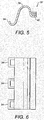
- the end catch 32 is in the form a sine wave.
- three spaced upwardly projecting hinges 34 extend through corresponding openings 36, shown in Figure 3 , in the container ends.
- the upper cap 38 of the catch 32 acts to bear against the top domed end 40 of the lid to hold the lid on the container and to bias the lid onto the container.
- the lid In order to attach the catch and to hold the ends of the lid the lid is first loosely mounted on the container. Then, with the catch 32 inverted from the position shown in Figure 5 , the hinges 34 are located through the openings 36 in the container. The catch is then pivoted upwardly about the hinge 34 until what is then an upwardly and inwardly extending wall 42 of the catch abuts an outwardly facing surface of the domed end 40 of the lid. Further urging of the catch in the rotational direction causes the wall 42 to slide over and up the domed end 40 with the cap 38 flexing to open the curve shown in Figure 5 . As the end wall 42 passes over the top of the dome the catch snaps into position. The opened curve of the cap 38 partially returns to the at rest position shown in Figure 5 . The resilience of that partial return coupled with a stretching of the sine wave shown in Figure 5 holds the lid firmly against the container 12.
- a flange 44 extends downwardly and outwardly terminates in an outwardly facing lip 46.
- the sides of the lid extend downwardly and outwardly in a flange 48 from the recess 26 with a kink 50 allowing the flange to extend over the end of the lip 46 and down below the lip 46.
- the flanges 44 and 48 are co-extensive they lie against each other or are closely spaced from each other. If only the end catches 32 are attached then there may be sufficient sealing along the sides for most applications without applying the side catches.
- the side catches 37 can be applied by a user urging their fingers around the end of the flange 48 to push the sides of the container in and at the same time pulling the flange 48 down and out and then back in to cause the catches 48 to be flexed under the lip 46 to the position shown in Figure 9 .
- Attachment is further enabled by the catches having ramps 39 that assist in urging the lip and flange apart as the lid is pushed down.
- the flexure of the flanges 48 holds the sides of the lid down against the rim 24 of the container to effect a firm sealing along the sides of the container.
- the side catches are released by flexing the flanges 48 outwardly.
- catches 37 On the side of the lid opposed to the sides of the container having the ports 16 and 18 there are four catches 37. At one end of the side catch the catch 37 is in line with the elastomeric portion 22 that in use seals the port 16. The space between that end catch 37 and the adjacent catch is greater than the space between other adjacent catches. In this way the concentration of the catches on the opposed side corresponds to the concentration of the elastomeric portions on the opposed side.
- the catches 37 in the region of the elastomeric portion 22 that seals the port 16 partly overlap each elastomeric portion in the elongate extent of that side.
- the remaining catches are in the region of the other four elastomeric portions 22.
- the catch 37 towards the end of that side is co-extensive with the end part of each elastomeric portion 22.
- the next three catches along the side partially overlap the end part of the next three elastomeric portions 22.
- the final catch 37 is adjacent to but spaced from the far end of the last elastomeric portion of those series.
- the catches 32 may have a hole 50 which is aligned with a hole 52 in the overhang of the container 12. Tie wraps 54 in a loop, possibly with a lock, can be passed through these holes to prevent removal of the catches and thereby prevent removal of the lid.
- the overhang of the lid may also include an aligned opening such that the catches, lid and container are all fastened together at each end.
- an attachment point is provided at each of the lower corners comprising a passage 56 extending from a lever side at each corner to the base at each corner.
- Tie wraps (not shown) can be passed through each passage 56 and around a base (not shown) so that the container can not be removed. Locks may be provided for the tie wraps.
- the container may be mounted off the ground, if required.
- the lid and the catches 37 may be integrally moulded and may be moulded of plastics.
- the container may comprise a moulding such as a moulding of plastics.
- the catches 32 may be moulded such as of plastics.
Landscapes
- Engineering & Computer Science (AREA)
- Architecture (AREA)
- Civil Engineering (AREA)
- Structural Engineering (AREA)
- Mechanical Engineering (AREA)
- Closures For Containers (AREA)
- Casings For Electric Apparatus (AREA)
Claims (13)
- Behältnisanordnung, die ein Behältnis (12) und einen getrennten Deckel (14) umfasst, wobei der Deckel und das Behältnis (12) so angeordnet sind, dass sie in der Lage sind durch Betätigung eines ersten und eines zweiten (37) Verschlusses verschiedener Art lösbar miteinander verbunden zu werden, wobei sich der Deckel, wenn er mit dem Behältnis verbunden ist, in einer abdichtenden Beziehung zu dem Behältnis befindet, wobei die zweite Art von Verschluss (37) integral mit dem Deckel oder dem Behältnis geformt ist und dazu angeordnet ist, sich nur durch Biegen unter Druck zu bewegen, wobei die zweite Art von Verschluss eine Rampe (39) umfasst, wobei die zweite Art von Verschluss eine Schnappverbindung umfasst, wobei die Rampe die Bewirkung der Schnappverbindung durch Wegdrücken mindestens eines Teils eines Abschnitts des Deckels oder Behältnisses bezüglich eines anderen Abschnitts des jeweils anderen von dem Deckel oder Behältnis voneinander, wenn der Deckel und das Behältnis zueinander gedrückt werden, unterstützt, wobei die zweite Art von Verschluss an dem Deckel oder Behältnis dahingehend wirkt, eine Verbindung zu bewirken, indem sich ein Rand des Verschlusses an einem Rand (46) des jeweils anderen von dem Deckel des Behältnisses vorbei bewegt und sich darunter erstreckt, dadurch gekennzeichnet, dass mehrere der zweiten Art von Verschluss entlang einer Seite des Behältnisses oder Deckels neben mindestens einer Öffnung (16, 18) im Bereich der Verbindungsstelle zwischen dem Deckel und dem Behältnis voneinander beabstandet sind, wobei sich im Gebrauch ein elektrisches Kabel durch diese Öffnung erstreckt.
- Anordnung nach Anspruch 1, wobei der Deckel und das Behältnis so angeordnet sind, dass sie sich in einer abdichtenden Beziehung befinden, wenn nur die erste Art von Verschluss (32) betätigt wird.
- Anordnung nach Anspruch 1 oder 2, wobei der erste Verschluss ein Verschlussglied (32) umfasst, das von dem Deckel und dem Behältnis trennbar ist.
- Anordnung nach einem vorhergehenden Anspruch, die mindestens eine Öffnung (18) aufweist, in der der Deckel und das Behältnis zum gegenseitigen Abdichten (20, 22) über die Öffnung angeordnet sind, wenn die erste und/oder die zweite Art von Verschluss bedient wird/werden, unabhängig davon, ob sich ein Kabel durch die Öffnung erstreckt oder nicht.
- Anordnung nach einem vorhergehenden Anspruch, die mindestens eine zweite Art von Verschluss (37) umfasst, die bei Betrachtung in Richtung der durch den Verschluss neben mindestens einer Öffnung ausgeübten Kraft zumindest teilweise koextensiv mit der Öffnung (16, 18) ist.
- Anordnung nach Anspruch 5, wobei mindestens eine zweite Art von Verschluss bei Betrachtung in der Richtung vollkommen koextensiv mit der Öffnung ist.
- Anordnung nach einem der Ansprüche 4 bis 6, wobei der Deckel und/oder das Behältnis eine Umfangsdichtung (28) enthält/enthalten und die Dichtung dazu angeordnet ist, mit einem federnden Abschnitt der Öffnung zusammenzuwirken, wenn sich der Deckel und das Behältnis in der Dichtungsanordnung befinden.
- Anordnung nach Anspruch 7, wobei sowohl der Deckel als auch das Behältnis federnde Abschnitte (20, 22) in dem Bereich der Öffnung enthalten, die dazu angeordnet sind, in einer abdichtenden Beziehung zusammenzuwirken, wenn der Deckel und das Behältnis verbunden sind.
- Anordnung nach einem der Ansprüche 4 bis 8, wobei die Öffnung (16, 18) an einer der Seiten des Behältnisses mit der zweiten Art von Verschluss positioniert ist, wobei dort weniger der zweiten Art von Verschluss auf der gegenüberliegenden Seite bezüglich der mit der Öffnung ist.
- Anordnung nach einem der Ansprüche 4 bis 8, die mehrere Öffnungen entlang einer Seite mit einer zweiten Art von Verschluss umfasst.
- Verfahren zum lösbaren Verbinden eines Deckels (14) und eines Behältnisses (12) zur Bildung einer Behältnisanordnung mit einem ersten (32) und einem zweiten Verschluss verschiedener Art, die zum lösbaren Verbinden des Deckels und des Behältnisses verwendet werden können, wobei die zweite Art von Verschluss integral mit dem Deckel oder dem Behältnis geformt ist und dazu angeordnet ist, sich nur durch Biegen unter Druck zu bewegen, wobei die zweite Art von Verschluss eine Rampe (39) umfasst, wobei das Verfahren lösbares Verbinden des Deckels und des Behältnisses in abdichtender Beziehung mit nur der zweiten Art von Verschluss durch Drücken des Deckels und des Behältnisses zueinander, um zu bewirken, dass die Rampe mindestens einen Abschnitt des Deckels oder des Behältnisses bezüglich eines anderen Abschnitts des jeweils anderen von dem Deckel oder Behältnis voneinander weg drückt, umfasst, wobei sich ein Rand der zweiten Art von Verschluss an einem Rand (46) des Behältnisses des Deckels oder Behältnisses vorbei bewegt und sich darunter erstreckt, um die Verbindung zu bewirken, dadurch gekennzeichnet, dass das Verfahren Verbinden mehrerer Verschlüsse der zweiten Art, die entlang einer Seite des Behältnisses oder Deckels neben mindestens einer Öffnung (16, 18) in dem Bereich der Verbindungsstelle zwischen dem Deckel und dem Behältnis voneinander beabstandet sind, umfasst, wobei sich im Gebrauch ein elektrisches Kabel durch diese Öffnung erstreckt.
- Verfahren nach Anspruch 11, das anschließendes Verbessern der Verbindung des Deckels und des Behältnisses durch Betätigung der ersten Art von Verschluss umfasst.
- Verfahren zum Abdichten eines Deckels und eines Behältnisses nach Anspruch 11 oder 12, wenn die Behältnisanordnung einem der Ansprüche 1 bis 10 entspricht.
Applications Claiming Priority (2)
| Application Number | Priority Date | Filing Date | Title |
|---|---|---|---|
| GB0821051.0A GB2465403B (en) | 2008-11-18 | 2008-11-18 | Container arrangement |
| PCT/GB2009/051457 WO2010058192A1 (en) | 2008-11-18 | 2009-10-29 | Container arrangement |
Publications (2)
| Publication Number | Publication Date |
|---|---|
| EP2347487A1 EP2347487A1 (de) | 2011-07-27 |
| EP2347487B1 true EP2347487B1 (de) | 2016-05-25 |
Family
ID=40194803
Family Applications (1)
| Application Number | Title | Priority Date | Filing Date |
|---|---|---|---|
| EP09745095.1A Active EP2347487B1 (de) | 2008-11-18 | 2009-10-29 | Containeranordnung |
Country Status (9)
| Country | Link |
|---|---|
| US (1) | US8881923B2 (de) |
| EP (1) | EP2347487B1 (de) |
| CN (1) | CN102217157B (de) |
| AU (1) | AU2009316984B2 (de) |
| DK (1) | DK2347487T3 (de) |
| GB (1) | GB2465403B (de) |
| HU (1) | HUE029666T2 (de) |
| NZ (1) | NZ592681A (de) |
| WO (1) | WO2010058192A1 (de) |
Families Citing this family (67)
| Publication number | Priority date | Publication date | Assignee | Title |
|---|---|---|---|---|
| JP6057178B2 (ja) * | 2013-10-11 | 2017-01-11 | 住友電装株式会社 | 電気接続箱 |
| US10952889B2 (en) | 2016-06-02 | 2021-03-23 | Purewick Corporation | Using wicking material to collect liquid for transport |
| US11806266B2 (en) | 2014-03-19 | 2023-11-07 | Purewick Corporation | Apparatus and methods for receiving discharged urine |
| US10226376B2 (en) | 2014-03-19 | 2019-03-12 | Purewick Corporation | Apparatus and methods for receiving discharged urine |
| US10390989B2 (en) | 2014-03-19 | 2019-08-27 | Purewick Corporation | Apparatus and methods for receiving discharged urine |
| US11376152B2 (en) | 2014-03-19 | 2022-07-05 | Purewick Corporation | Apparatus and methods for receiving discharged urine |
| US10973678B2 (en) | 2016-07-27 | 2021-04-13 | Purewick Corporation | Apparatus and methods for receiving discharged urine |
| US10376406B2 (en) | 2016-07-27 | 2019-08-13 | Purewick Corporation | Male urine collection device using wicking material |
| WO2018144463A1 (en) | 2017-01-31 | 2018-08-09 | Purewick Corporation | Apparatus and methods for receiving discharged urine |
| EP3787569B1 (de) | 2018-05-01 | 2025-07-16 | Purewick Corporation | Flüssigkeitssammelvorrichtungen und -systeme |
| JP7072084B2 (ja) | 2018-05-01 | 2022-05-19 | ピュアウィック コーポレイション | 流体収集装置、関連システム、及び関連方法 |
| AU2019262945B2 (en) | 2018-05-01 | 2022-08-25 | Purewick Corporation | Fluid collection devices and methods of using the same |
| US11944740B2 (en) | 2018-05-01 | 2024-04-02 | Purewick Corporation | Fluid collection devices, related systems, and related methods |
| EP3787571B1 (de) | 2018-05-01 | 2022-06-01 | Purewick Corporation | Fluidauffangbekleidung |
| AU2019262939A1 (en) | 2018-05-01 | 2020-11-26 | Purewick Corporation | Fluid collection devices, systems, and methods |
| CA3143904C (en) | 2019-06-21 | 2023-11-28 | Purewick Corporation | Fluid collection devices including a base securement area, and related systems and methods |
| ES2961269T3 (es) | 2019-07-11 | 2024-03-11 | Purewick Corp | Dispositivos y sistemas de recogida de líquido |
| WO2021016026A1 (en) | 2019-07-19 | 2021-01-28 | Purewick Corporation | Fluid collection devices including at least one shape memory material |
| EP4051190B1 (de) | 2019-10-28 | 2024-05-22 | Purewick Corporation | Fluidsammelanordnungen mit einem probenport |
| EP4559443A3 (de) | 2020-01-03 | 2025-06-18 | Purewick Corporation | Urinsammelvorrichtungen mit einem relativ breiten teil und einem länglichen teil und zugehörige verfahren |
| USD1018282S1 (en) | 2020-01-28 | 2024-03-19 | Congruens Group, Llc | Component for a food container |
| USD992413S1 (en) | 2020-02-21 | 2023-07-18 | Zume, Inc. | Food container |
| WO2021188817A1 (en) | 2020-03-19 | 2021-09-23 | Purewick Corporation | Fluid collection assemblies including one or more movement enhancing features |
| US12521288B2 (en) | 2020-03-26 | 2026-01-13 | Purewick Corporation | Multi-layer urine capture device and related methods |
| WO2021207621A1 (en) | 2020-04-10 | 2021-10-14 | Purewick Corporation | Fluid collection assemblies including one or more leak prevention features |
| US12465514B2 (en) | 2020-04-17 | 2025-11-11 | Purewick Corporation | Fluid collection devices, systems, and methods securing a protruding portion in position for use |
| WO2021211801A1 (en) | 2020-04-17 | 2021-10-21 | Purewick Corporation | Fluid collection assemblies including a fluid impermeable barrier having a sump and a base |
| US12472090B2 (en) | 2020-04-17 | 2025-11-18 | Purewick Corporation | Female external catheter devices having a urethral cup, and related systems and methods |
| US12491104B2 (en) | 2020-04-20 | 2025-12-09 | Purewick Corporation | Fluid collection devices adjustable between a vacuum-based orientation and a gravity-based orientation, and related systems and methods |
| US12048643B2 (en) | 2020-05-27 | 2024-07-30 | Purewick Corporation | Fluid collection assemblies including at least one inflation device and methods and systems of using the same |
| USD967409S1 (en) | 2020-07-15 | 2022-10-18 | Purewick Corporation | Urine collection apparatus cover |
| US20220031926A1 (en) * | 2020-07-28 | 2022-02-03 | Design Department, Inc. | Spherical Canister |
| US12440371B2 (en) | 2020-08-06 | 2025-10-14 | Purewick Corporation | Fluid collection system including a garment and a fluid collection device |
| US12350187B2 (en) | 2020-08-11 | 2025-07-08 | Purewick Corporation | Fluid collection assemblies defining waist and leg openings |
| EP4210643A1 (de) | 2020-09-09 | 2023-07-19 | Purewick Corporation | Flüssigkeitssammelvorrichtungen, -systeme und -verfahren |
| US12156792B2 (en) | 2020-09-10 | 2024-12-03 | Purewick Corporation | Fluid collection assemblies including at least one inflation device |
| US11801186B2 (en) | 2020-09-10 | 2023-10-31 | Purewick Corporation | Urine storage container handle and lid accessories |
| US12042423B2 (en) | 2020-10-07 | 2024-07-23 | Purewick Corporation | Fluid collection systems including at least one tensioning element |
| US12440370B2 (en) | 2020-10-21 | 2025-10-14 | Purewick Corporation | Apparatus with compressible casing for receiving discharged urine |
| US12569365B2 (en) | 2020-10-21 | 2026-03-10 | Purewick Corporation | Fluid collection assemblies including at least one shape memory material disposed in the conduit |
| US12257174B2 (en) | 2020-10-21 | 2025-03-25 | Purewick Corporation | Fluid collection assemblies including at least one of a protrusion or at least one expandable material |
| US12208031B2 (en) | 2020-10-21 | 2025-01-28 | Purewick Corporation | Adapters for fluid collection devices |
| US12048644B2 (en) | 2020-11-03 | 2024-07-30 | Purewick Corporation | Apparatus for receiving discharged urine |
| US12070432B2 (en) | 2020-11-11 | 2024-08-27 | Purewick Corporation | Urine collection system including a flow meter and related methods |
| US12245967B2 (en) | 2020-11-18 | 2025-03-11 | Purewick Corporation | Fluid collection assemblies including an adjustable spine |
| US12599495B2 (en) | 2021-01-05 | 2026-04-14 | Purewick Corporation | Male external catheter with attachment interface configured to bias against penis |
| US12268627B2 (en) | 2021-01-06 | 2025-04-08 | Purewick Corporation | Fluid collection assemblies including at least one securement body |
| JP2024503636A (ja) | 2021-01-07 | 2024-01-26 | ピュアウィック コーポレイション | 車椅子に固定可能な尿収集システムおよび関連する方法 |
| EP4349306A3 (de) | 2021-01-19 | 2024-06-05 | Purewick Corporation | Flüssigkeitssammelvorrichtungen mit variabler passform, systeme und verfahren |
| US12178735B2 (en) | 2021-02-09 | 2024-12-31 | Purewick Corporation | Noise reduction for a urine suction system |
| EP4274524B1 (de) | 2021-02-26 | 2024-08-28 | Purewick Corporation | Flüssigkeitsaufnahmegerät, konfiguriert als ein männliches urinaufnahmegerät |
| US12551385B2 (en) | 2021-03-05 | 2026-02-17 | Purewick Corporation | Fluid collection assembly including a tube having porous wicking material for improved fluid transport |
| US12558472B2 (en) | 2021-03-05 | 2026-02-24 | Purewick Corporation | Portable fluid collection systems with storage and related methods |
| US11938054B2 (en) | 2021-03-10 | 2024-03-26 | Purewick Corporation | Bodily waste and fluid collection with sacral pad |
| US12458525B2 (en) | 2021-03-10 | 2025-11-04 | Purewick Corporation | Acoustic silencer for a urine suction system |
| US12029677B2 (en) | 2021-04-06 | 2024-07-09 | Purewick Corporation | Fluid collection devices having a collection bag, and related systems and methods |
| US12233003B2 (en) | 2021-04-29 | 2025-02-25 | Purewick Corporation | Fluid collection assemblies including at least one length adjusting feature |
| US11939110B2 (en) * | 2021-05-21 | 2024-03-26 | Monoflo International, Inc. | Container lid with nest segment |
| US12251333B2 (en) | 2021-05-21 | 2025-03-18 | Purewick Corporation | Fluid collection assemblies including at least one inflation device and methods and systems of using the same |
| US12324767B2 (en) | 2021-05-24 | 2025-06-10 | Purewick Corporation | Fluid collection assembly including a customizable external support and related methods |
| US12150885B2 (en) | 2021-05-26 | 2024-11-26 | Purewick Corporation | Fluid collection system including a cleaning system and methods |
| USD964943S1 (en) * | 2021-05-28 | 2022-09-27 | Mengcheng County Yiyang E-Commerce Co., Ltd. | Electrical connection box |
| US12575960B2 (en) | 2021-06-24 | 2026-03-17 | Purewick Corporation | Urine collection systems having one or more of volume, pressure, or flow indicators, and related methods |
| US12551366B2 (en) | 2021-08-02 | 2026-02-17 | Purewick Corporation | Fluid collection devices having multiple fluid collection regions, and related systems and methods |
| US12594062B2 (en) | 2021-09-08 | 2026-04-07 | Purewick Corporation | Fluid collection assemblies including an extension |
| USD984968S1 (en) * | 2022-12-23 | 2023-05-02 | Kang Chen | Outdoor electrical box |
| USD1007857S1 (en) * | 2023-05-23 | 2023-12-19 | Fei Yang | Electrical box |
Family Cites Families (9)
| Publication number | Priority date | Publication date | Assignee | Title |
|---|---|---|---|---|
| US3510023A (en) | 1968-08-14 | 1970-05-05 | Inland Steel Co | Plastic container and lid therefor |
| GB1415242A (en) * | 1973-01-10 | 1975-11-26 | Anchro Chemical Developments L | Containers |
| US3858755A (en) * | 1973-04-02 | 1975-01-07 | Ametek Inc | Meter box with cover having biased snap-lock |
| US4365723A (en) * | 1981-07-22 | 1982-12-28 | Palermo Michael A | Pedestal housing for cable television components |
| FR2705857B1 (fr) | 1993-05-24 | 1995-08-11 | Legrand Sa | Boîte à couvercle rapporté par encliquetage, notamment pour appareillage électrique. |
| US6362419B1 (en) * | 1999-06-01 | 2002-03-26 | Utility Marketing Corporation | Pedestal structure for housing electrical power connections and other equipment |
| US6364152B1 (en) * | 2000-04-12 | 2002-04-02 | Dart Industries Inc. | Food storage container |
| JP3831213B2 (ja) * | 2001-06-12 | 2006-10-11 | 矢崎総業株式会社 | 電気接続箱の二重壁構造 |
| EP1622280A1 (de) * | 2004-07-29 | 2006-02-01 | Hana Cobi Co., Ltd. | Gehäuse für ein Mobiltelefon |
-
2008
- 2008-11-18 GB GB0821051.0A patent/GB2465403B/en active Active
-
2009
- 2009-10-29 DK DK09745095.1T patent/DK2347487T3/en active
- 2009-10-29 WO PCT/GB2009/051457 patent/WO2010058192A1/en not_active Ceased
- 2009-10-29 US US13/128,715 patent/US8881923B2/en active Active
- 2009-10-29 NZ NZ592681A patent/NZ592681A/en not_active IP Right Cessation
- 2009-10-29 AU AU2009316984A patent/AU2009316984B2/en active Active
- 2009-10-29 EP EP09745095.1A patent/EP2347487B1/de active Active
- 2009-10-29 CN CN200980146058.4A patent/CN102217157B/zh active Active
- 2009-10-29 HU HUE09745095A patent/HUE029666T2/en unknown
Non-Patent Citations (1)
| Title |
|---|
| None * |
Also Published As
| Publication number | Publication date |
|---|---|
| GB2465403B (en) | 2013-02-13 |
| US8881923B2 (en) | 2014-11-11 |
| EP2347487A1 (de) | 2011-07-27 |
| GB2465403A (en) | 2010-05-19 |
| AU2009316984B2 (en) | 2014-05-08 |
| CN102217157A (zh) | 2011-10-12 |
| CN102217157B (zh) | 2014-06-04 |
| NZ592681A (en) | 2012-07-27 |
| HUE029666T2 (en) | 2017-03-28 |
| WO2010058192A1 (en) | 2010-05-27 |
| AU2009316984A1 (en) | 2010-05-27 |
| DK2347487T3 (en) | 2016-09-05 |
| GB0821051D0 (en) | 2008-12-24 |
| US20110278290A1 (en) | 2011-11-17 |
Similar Documents
| Publication | Publication Date | Title |
|---|---|---|
| EP2347487B1 (de) | Containeranordnung | |
| US7547051B2 (en) | Locking system for grade level enclosures | |
| US7265292B2 (en) | Weatherproof while-in-use electrical receptacle cover assembly | |
| AU658205B2 (en) | Outdoor electrical outlet cover | |
| US6133531A (en) | Weatherproof outlet cover | |
| US6979777B2 (en) | Weatherproof electrical enclosure having an adjustable-position cover | |
| US7598453B1 (en) | Horizontal and vertical mountable electrical device cover | |
| US7462777B2 (en) | Dual hinge recess weatherproof electrical box assembly | |
| US5317108A (en) | Weather-resistant electrical outlet cover assembly | |
| US4660912A (en) | Protective cover for electrical outlet | |
| CA2451456C (en) | Water resistant electrical floor box cover assembly | |
| US7439444B1 (en) | Horizontal and vertical in-use electrical device cover | |
| US20180265263A1 (en) | Touch and seal self-closing container | |
| US8357852B2 (en) | Latching floor box cover | |
| US8921695B2 (en) | Latching floor box cover | |
| US20080047730A1 (en) | Weatherproof cover assembly | |
| CA2280218A1 (en) | Weatherproof outlet cover | |
| US20100200533A1 (en) | Vial with push-button release closure | |
| US6437242B1 (en) | Opening mechanism for electrical outlet box | |
| RU2359886C2 (ru) | Тарный комплект | |
| EP1434327A1 (de) | Verbindungsdose vorzugsweise für elektrische Einrichtungen | |
| RU2093439C1 (ru) | Захват-замок | |
| JPH088005A (ja) | デスク用コンセント装置 | |
| KR20150125119A (ko) | 전기자동차의 인렛 | |
| KR920002636Y1 (ko) | 방우형 콘센트 |
Legal Events
| Date | Code | Title | Description |
|---|---|---|---|
| PUAI | Public reference made under article 153(3) epc to a published international application that has entered the european phase |
Free format text: ORIGINAL CODE: 0009012 |
|
| 17P | Request for examination filed |
Effective date: 20110504 |
|
| AK | Designated contracting states |
Kind code of ref document: A1 Designated state(s): AT BE BG CH CY CZ DE DK EE ES FI FR GB GR HR HU IE IS IT LI LT LU LV MC MK MT NL NO PL PT RO SE SI SK SM TR |
|
| AX | Request for extension of the european patent |
Extension state: AL BA RS |
|
| DAX | Request for extension of the european patent (deleted) | ||
| 17Q | First examination report despatched |
Effective date: 20150923 |
|
| GRAP | Despatch of communication of intention to grant a patent |
Free format text: ORIGINAL CODE: EPIDOSNIGR1 |
|
| INTG | Intention to grant announced |
Effective date: 20160308 |
|
| GRAS | Grant fee paid |
Free format text: ORIGINAL CODE: EPIDOSNIGR3 |
|
| GRAA | (expected) grant |
Free format text: ORIGINAL CODE: 0009210 |
|
| AK | Designated contracting states |
Kind code of ref document: B1 Designated state(s): AT BE BG CH CY CZ DE DK EE ES FI FR GB GR HR HU IE IS IT LI LT LU LV MC MK MT NL NO PL PT RO SE SI SK SM TR |
|
| REG | Reference to a national code |
Ref country code: GB Ref legal event code: FG4D |
|
| REG | Reference to a national code |
Ref country code: CH Ref legal event code: EP |
|
| REG | Reference to a national code |
Ref country code: IE Ref legal event code: FG4D Ref country code: AT Ref legal event code: REF Ref document number: 803030 Country of ref document: AT Kind code of ref document: T Effective date: 20160615 |
|
| REG | Reference to a national code |
Ref country code: DE Ref legal event code: R096 Ref document number: 602009038876 Country of ref document: DE |
|
| REG | Reference to a national code |
Ref country code: NL Ref legal event code: FP |
|
| REG | Reference to a national code |
Ref country code: DK Ref legal event code: T3 Effective date: 20160901 |
|
| REG | Reference to a national code |
Ref country code: LT Ref legal event code: MG4D |
|
| REG | Reference to a national code |
Ref country code: FR Ref legal event code: PLFP Year of fee payment: 8 |
|
| PG25 | Lapsed in a contracting state [announced via postgrant information from national office to epo] |
Ref country code: LT Free format text: LAPSE BECAUSE OF FAILURE TO SUBMIT A TRANSLATION OF THE DESCRIPTION OR TO PAY THE FEE WITHIN THE PRESCRIBED TIME-LIMIT Effective date: 20160525 Ref country code: FI Free format text: LAPSE BECAUSE OF FAILURE TO SUBMIT A TRANSLATION OF THE DESCRIPTION OR TO PAY THE FEE WITHIN THE PRESCRIBED TIME-LIMIT Effective date: 20160525 Ref country code: NO Free format text: LAPSE BECAUSE OF FAILURE TO SUBMIT A TRANSLATION OF THE DESCRIPTION OR TO PAY THE FEE WITHIN THE PRESCRIBED TIME-LIMIT Effective date: 20160825 |
|
| REG | Reference to a national code |
Ref country code: AT Ref legal event code: MK05 Ref document number: 803030 Country of ref document: AT Kind code of ref document: T Effective date: 20160525 |
|
| PG25 | Lapsed in a contracting state [announced via postgrant information from national office to epo] |
Ref country code: ES Free format text: LAPSE BECAUSE OF FAILURE TO SUBMIT A TRANSLATION OF THE DESCRIPTION OR TO PAY THE FEE WITHIN THE PRESCRIBED TIME-LIMIT Effective date: 20160525 Ref country code: PT Free format text: LAPSE BECAUSE OF FAILURE TO SUBMIT A TRANSLATION OF THE DESCRIPTION OR TO PAY THE FEE WITHIN THE PRESCRIBED TIME-LIMIT Effective date: 20160926 Ref country code: HR Free format text: LAPSE BECAUSE OF FAILURE TO SUBMIT A TRANSLATION OF THE DESCRIPTION OR TO PAY THE FEE WITHIN THE PRESCRIBED TIME-LIMIT Effective date: 20160525 Ref country code: GR Free format text: LAPSE BECAUSE OF FAILURE TO SUBMIT A TRANSLATION OF THE DESCRIPTION OR TO PAY THE FEE WITHIN THE PRESCRIBED TIME-LIMIT Effective date: 20160826 Ref country code: SE Free format text: LAPSE BECAUSE OF FAILURE TO SUBMIT A TRANSLATION OF THE DESCRIPTION OR TO PAY THE FEE WITHIN THE PRESCRIBED TIME-LIMIT Effective date: 20160525 Ref country code: LV Free format text: LAPSE BECAUSE OF FAILURE TO SUBMIT A TRANSLATION OF THE DESCRIPTION OR TO PAY THE FEE WITHIN THE PRESCRIBED TIME-LIMIT Effective date: 20160525 |
|
| PG25 | Lapsed in a contracting state [announced via postgrant information from national office to epo] |
Ref country code: IT Free format text: LAPSE BECAUSE OF FAILURE TO SUBMIT A TRANSLATION OF THE DESCRIPTION OR TO PAY THE FEE WITHIN THE PRESCRIBED TIME-LIMIT Effective date: 20160525 |
|
| PG25 | Lapsed in a contracting state [announced via postgrant information from national office to epo] |
Ref country code: CZ Free format text: LAPSE BECAUSE OF FAILURE TO SUBMIT A TRANSLATION OF THE DESCRIPTION OR TO PAY THE FEE WITHIN THE PRESCRIBED TIME-LIMIT Effective date: 20160525 Ref country code: SK Free format text: LAPSE BECAUSE OF FAILURE TO SUBMIT A TRANSLATION OF THE DESCRIPTION OR TO PAY THE FEE WITHIN THE PRESCRIBED TIME-LIMIT Effective date: 20160525 Ref country code: EE Free format text: LAPSE BECAUSE OF FAILURE TO SUBMIT A TRANSLATION OF THE DESCRIPTION OR TO PAY THE FEE WITHIN THE PRESCRIBED TIME-LIMIT Effective date: 20160525 Ref country code: RO Free format text: LAPSE BECAUSE OF FAILURE TO SUBMIT A TRANSLATION OF THE DESCRIPTION OR TO PAY THE FEE WITHIN THE PRESCRIBED TIME-LIMIT Effective date: 20160525 |
|
| PGFP | Annual fee paid to national office [announced via postgrant information from national office to epo] |
Ref country code: HU Payment date: 20161018 Year of fee payment: 8 |
|
| PG25 | Lapsed in a contracting state [announced via postgrant information from national office to epo] |
Ref country code: SM Free format text: LAPSE BECAUSE OF FAILURE TO SUBMIT A TRANSLATION OF THE DESCRIPTION OR TO PAY THE FEE WITHIN THE PRESCRIBED TIME-LIMIT Effective date: 20160525 Ref country code: PL Free format text: LAPSE BECAUSE OF FAILURE TO SUBMIT A TRANSLATION OF THE DESCRIPTION OR TO PAY THE FEE WITHIN THE PRESCRIBED TIME-LIMIT Effective date: 20160525 Ref country code: AT Free format text: LAPSE BECAUSE OF FAILURE TO SUBMIT A TRANSLATION OF THE DESCRIPTION OR TO PAY THE FEE WITHIN THE PRESCRIBED TIME-LIMIT Effective date: 20160525 |
|
| REG | Reference to a national code |
Ref country code: DE Ref legal event code: R097 Ref document number: 602009038876 Country of ref document: DE |
|
| REG | Reference to a national code |
Ref country code: HU Ref legal event code: AG4A Ref document number: E029666 Country of ref document: HU |
|
| PLBE | No opposition filed within time limit |
Free format text: ORIGINAL CODE: 0009261 |
|
| STAA | Information on the status of an ep patent application or granted ep patent |
Free format text: STATUS: NO OPPOSITION FILED WITHIN TIME LIMIT |
|
| 26N | No opposition filed |
Effective date: 20170228 |
|
| PG25 | Lapsed in a contracting state [announced via postgrant information from national office to epo] |
Ref country code: SI Free format text: LAPSE BECAUSE OF FAILURE TO SUBMIT A TRANSLATION OF THE DESCRIPTION OR TO PAY THE FEE WITHIN THE PRESCRIBED TIME-LIMIT Effective date: 20160525 |
|
| REG | Reference to a national code |
Ref country code: IE Ref legal event code: MM4A |
|
| PG25 | Lapsed in a contracting state [announced via postgrant information from national office to epo] |
Ref country code: LU Free format text: LAPSE BECAUSE OF NON-PAYMENT OF DUE FEES Effective date: 20161029 |
|
| REG | Reference to a national code |
Ref country code: FR Ref legal event code: PLFP Year of fee payment: 9 |
|
| PG25 | Lapsed in a contracting state [announced via postgrant information from national office to epo] |
Ref country code: IE Free format text: LAPSE BECAUSE OF NON-PAYMENT OF DUE FEES Effective date: 20161029 |
|
| PG25 | Lapsed in a contracting state [announced via postgrant information from national office to epo] |
Ref country code: CY Free format text: LAPSE BECAUSE OF FAILURE TO SUBMIT A TRANSLATION OF THE DESCRIPTION OR TO PAY THE FEE WITHIN THE PRESCRIBED TIME-LIMIT Effective date: 20160525 |
|
| PG25 | Lapsed in a contracting state [announced via postgrant information from national office to epo] |
Ref country code: TR Free format text: LAPSE BECAUSE OF FAILURE TO SUBMIT A TRANSLATION OF THE DESCRIPTION OR TO PAY THE FEE WITHIN THE PRESCRIBED TIME-LIMIT Effective date: 20160525 Ref country code: MT Free format text: LAPSE BECAUSE OF NON-PAYMENT OF DUE FEES Effective date: 20161031 Ref country code: IS Free format text: LAPSE BECAUSE OF FAILURE TO SUBMIT A TRANSLATION OF THE DESCRIPTION OR TO PAY THE FEE WITHIN THE PRESCRIBED TIME-LIMIT Effective date: 20160525 Ref country code: MK Free format text: LAPSE BECAUSE OF FAILURE TO SUBMIT A TRANSLATION OF THE DESCRIPTION OR TO PAY THE FEE WITHIN THE PRESCRIBED TIME-LIMIT Effective date: 20160525 Ref country code: MC Free format text: LAPSE BECAUSE OF FAILURE TO SUBMIT A TRANSLATION OF THE DESCRIPTION OR TO PAY THE FEE WITHIN THE PRESCRIBED TIME-LIMIT Effective date: 20160525 |
|
| PG25 | Lapsed in a contracting state [announced via postgrant information from national office to epo] |
Ref country code: BG Free format text: LAPSE BECAUSE OF FAILURE TO SUBMIT A TRANSLATION OF THE DESCRIPTION OR TO PAY THE FEE WITHIN THE PRESCRIBED TIME-LIMIT Effective date: 20160525 |
|
| PG25 | Lapsed in a contracting state [announced via postgrant information from national office to epo] |
Ref country code: HU Free format text: LAPSE BECAUSE OF NON-PAYMENT OF DUE FEES Effective date: 20171030 |
|
| REG | Reference to a national code |
Ref country code: FR Ref legal event code: PLFP Year of fee payment: 10 |
|
| REG | Reference to a national code |
Ref country code: CH Ref legal event code: U11 Free format text: ST27 STATUS EVENT CODE: U-0-0-U10-U11 (AS PROVIDED BY THE NATIONAL OFFICE) Effective date: 20251101 |
|
| PGFP | Annual fee paid to national office [announced via postgrant information from national office to epo] |
Ref country code: NL Payment date: 20251021 Year of fee payment: 17 |
|
| PGFP | Annual fee paid to national office [announced via postgrant information from national office to epo] |
Ref country code: DE Payment date: 20251021 Year of fee payment: 17 |
|
| PGFP | Annual fee paid to national office [announced via postgrant information from national office to epo] |
Ref country code: GB Payment date: 20251009 Year of fee payment: 17 |
|
| PGFP | Annual fee paid to national office [announced via postgrant information from national office to epo] |
Ref country code: DK Payment date: 20251027 Year of fee payment: 17 |
|
| PGFP | Annual fee paid to national office [announced via postgrant information from national office to epo] |
Ref country code: FR Payment date: 20251029 Year of fee payment: 17 |
|
| PGFP | Annual fee paid to national office [announced via postgrant information from national office to epo] |
Ref country code: BE Payment date: 20251021 Year of fee payment: 17 |
|
| PGFP | Annual fee paid to national office [announced via postgrant information from national office to epo] |
Ref country code: CH Payment date: 20251101 Year of fee payment: 17 |