EP2347829B1 - Dispositif de collecte de poussiere - Google Patents
Dispositif de collecte de poussiere Download PDFInfo
- Publication number
- EP2347829B1 EP2347829B1 EP09825855.1A EP09825855A EP2347829B1 EP 2347829 B1 EP2347829 B1 EP 2347829B1 EP 09825855 A EP09825855 A EP 09825855A EP 2347829 B1 EP2347829 B1 EP 2347829B1
- Authority
- EP
- European Patent Office
- Prior art keywords
- electrode
- dust
- grid holes
- collecting
- dust collecting
- Prior art date
- Legal status (The legal status is an assumption and is not a legal conclusion. Google has not performed a legal analysis and makes no representation as to the accuracy of the status listed.)
- Not-in-force
Links
- 239000000428 dust Substances 0.000 title claims description 219
- 238000005192 partition Methods 0.000 claims description 78
- 239000000463 material Substances 0.000 claims description 12
- 239000011347 resin Substances 0.000 claims description 12
- 229920005989 resin Polymers 0.000 claims description 12
- 238000011144 upstream manufacturing Methods 0.000 claims description 10
- 239000007769 metal material Substances 0.000 claims description 8
- 230000002093 peripheral effect Effects 0.000 description 52
- 239000003054 catalyst Substances 0.000 description 10
- 230000005684 electric field Effects 0.000 description 10
- 238000004519 manufacturing process Methods 0.000 description 8
- 238000011045 prefiltration Methods 0.000 description 8
- 230000000052 comparative effect Effects 0.000 description 7
- 239000002184 metal Substances 0.000 description 3
- 229910052751 metal Inorganic materials 0.000 description 3
- 231100000614 poison Toxicity 0.000 description 2
- 239000000126 substance Substances 0.000 description 2
- 239000003440 toxic substance Substances 0.000 description 2
- PWHULOQIROXLJO-UHFFFAOYSA-N Manganese Chemical compound [Mn] PWHULOQIROXLJO-UHFFFAOYSA-N 0.000 description 1
- 229910000639 Spring steel Inorganic materials 0.000 description 1
- 238000010521 absorption reaction Methods 0.000 description 1
- 238000004887 air purification Methods 0.000 description 1
- 230000000694 effects Effects 0.000 description 1
- 238000001746 injection moulding Methods 0.000 description 1
- 238000003780 insertion Methods 0.000 description 1
- 230000037431 insertion Effects 0.000 description 1
- 238000012423 maintenance Methods 0.000 description 1
- 229910052748 manganese Inorganic materials 0.000 description 1
- 239000011572 manganese Substances 0.000 description 1
- 238000000034 method Methods 0.000 description 1
- 239000010970 precious metal Substances 0.000 description 1
- 239000000243 solution Substances 0.000 description 1
Images


Classifications
-
- B—PERFORMING OPERATIONS; TRANSPORTING
- B03—SEPARATION OF SOLID MATERIALS USING LIQUIDS OR USING PNEUMATIC TABLES OR JIGS; MAGNETIC OR ELECTROSTATIC SEPARATION OF SOLID MATERIALS FROM SOLID MATERIALS OR FLUIDS; SEPARATION BY HIGH-VOLTAGE ELECTRIC FIELDS
- B03C—MAGNETIC OR ELECTROSTATIC SEPARATION OF SOLID MATERIALS FROM SOLID MATERIALS OR FLUIDS; SEPARATION BY HIGH-VOLTAGE ELECTRIC FIELDS
- B03C3/00—Separating dispersed particles from gases or vapour, e.g. air, by electrostatic effect
- B03C3/34—Constructional details or accessories or operation thereof
- B03C3/40—Electrode constructions
-
- B—PERFORMING OPERATIONS; TRANSPORTING
- B03—SEPARATION OF SOLID MATERIALS USING LIQUIDS OR USING PNEUMATIC TABLES OR JIGS; MAGNETIC OR ELECTROSTATIC SEPARATION OF SOLID MATERIALS FROM SOLID MATERIALS OR FLUIDS; SEPARATION BY HIGH-VOLTAGE ELECTRIC FIELDS
- B03C—MAGNETIC OR ELECTROSTATIC SEPARATION OF SOLID MATERIALS FROM SOLID MATERIALS OR FLUIDS; SEPARATION BY HIGH-VOLTAGE ELECTRIC FIELDS
- B03C3/00—Separating dispersed particles from gases or vapour, e.g. air, by electrostatic effect
- B03C3/01—Pretreatment of the gases prior to electrostatic precipitation
- B03C3/011—Prefiltering; Flow controlling
-
- B—PERFORMING OPERATIONS; TRANSPORTING
- B03—SEPARATION OF SOLID MATERIALS USING LIQUIDS OR USING PNEUMATIC TABLES OR JIGS; MAGNETIC OR ELECTROSTATIC SEPARATION OF SOLID MATERIALS FROM SOLID MATERIALS OR FLUIDS; SEPARATION BY HIGH-VOLTAGE ELECTRIC FIELDS
- B03C—MAGNETIC OR ELECTROSTATIC SEPARATION OF SOLID MATERIALS FROM SOLID MATERIALS OR FLUIDS; SEPARATION BY HIGH-VOLTAGE ELECTRIC FIELDS
- B03C3/00—Separating dispersed particles from gases or vapour, e.g. air, by electrostatic effect
- B03C3/02—Plant or installations having external electricity supply
- B03C3/04—Plant or installations having external electricity supply dry type
- B03C3/08—Plant or installations having external electricity supply dry type characterised by presence of stationary flat electrodes arranged with their flat surfaces parallel to the gas stream
-
- B—PERFORMING OPERATIONS; TRANSPORTING
- B03—SEPARATION OF SOLID MATERIALS USING LIQUIDS OR USING PNEUMATIC TABLES OR JIGS; MAGNETIC OR ELECTROSTATIC SEPARATION OF SOLID MATERIALS FROM SOLID MATERIALS OR FLUIDS; SEPARATION BY HIGH-VOLTAGE ELECTRIC FIELDS
- B03C—MAGNETIC OR ELECTROSTATIC SEPARATION OF SOLID MATERIALS FROM SOLID MATERIALS OR FLUIDS; SEPARATION BY HIGH-VOLTAGE ELECTRIC FIELDS
- B03C3/00—Separating dispersed particles from gases or vapour, e.g. air, by electrostatic effect
- B03C3/02—Plant or installations having external electricity supply
- B03C3/04—Plant or installations having external electricity supply dry type
- B03C3/14—Plant or installations having external electricity supply dry type characterised by the additional use of mechanical effects, e.g. gravity
- B03C3/155—Filtration
-
- B—PERFORMING OPERATIONS; TRANSPORTING
- B03—SEPARATION OF SOLID MATERIALS USING LIQUIDS OR USING PNEUMATIC TABLES OR JIGS; MAGNETIC OR ELECTROSTATIC SEPARATION OF SOLID MATERIALS FROM SOLID MATERIALS OR FLUIDS; SEPARATION BY HIGH-VOLTAGE ELECTRIC FIELDS
- B03C—MAGNETIC OR ELECTROSTATIC SEPARATION OF SOLID MATERIALS FROM SOLID MATERIALS OR FLUIDS; SEPARATION BY HIGH-VOLTAGE ELECTRIC FIELDS
- B03C3/00—Separating dispersed particles from gases or vapour, e.g. air, by electrostatic effect
- B03C3/34—Constructional details or accessories or operation thereof
- B03C3/40—Electrode constructions
- B03C3/45—Collecting-electrodes
-
- B—PERFORMING OPERATIONS; TRANSPORTING
- B03—SEPARATION OF SOLID MATERIALS USING LIQUIDS OR USING PNEUMATIC TABLES OR JIGS; MAGNETIC OR ELECTROSTATIC SEPARATION OF SOLID MATERIALS FROM SOLID MATERIALS OR FLUIDS; SEPARATION BY HIGH-VOLTAGE ELECTRIC FIELDS
- B03C—MAGNETIC OR ELECTROSTATIC SEPARATION OF SOLID MATERIALS FROM SOLID MATERIALS OR FLUIDS; SEPARATION BY HIGH-VOLTAGE ELECTRIC FIELDS
- B03C3/00—Separating dispersed particles from gases or vapour, e.g. air, by electrostatic effect
- B03C3/34—Constructional details or accessories or operation thereof
- B03C3/40—Electrode constructions
- B03C3/45—Collecting-electrodes
- B03C3/47—Collecting-electrodes flat, e.g. plates, discs, gratings
Definitions
- Patent Document 1 discloses a dust collector using two grid-like electrodes.
- the dust collector includes a first electrode, a second electrode, and a power supply for applying a voltage to both electrodes.
- the first electrode and the second electrode substantially have the same structures.
- each of those electrodes includes a base having a grid structure, and protrusions protruding in the axial direction of the grid holes from the base.
- the protrusions are formed at the side end portions of the respective grid holes. That is, in those electrodes, there is a one-to-one correspondence between the side end portions of the grid holes and the protrusions.
- the two electrodes are positioned to face each other, so that the protrusions of the first electrode are inserted into the grid holes of the second electrode, and the protrusions of the second electrode are inserted into the grid holes of the first electrode.
- Patent Document 1 Japanese Patent Publication No. 2008-18425
- a first aspect of the invention is directed to a dust collector that includes a first electrode (40) that is a dust collection electrode, and a second electrode (50) that is a high voltage electrode, wherein the electrodes comprise, and bases (41, 51) each having a grid structure, and a plurality of protrusions (42, 52) protruding in the axial direction of grid holes (46, 56) from the bases (41, 51), respectively, the two electrodes (40, 50) being positioned to face each other, each of the protrusions (42) of the first electrode (40) being inserted into each corresponding one of the grid holes (56) of the second electrode (50), each of the protrusions (52) of the second electrode (50) being inserted into each corresponding one of the grid holes (46) of the first electrode (40), dust collecting surfaces to collect dust from an air to be processed being formed on surfaces of the first electrode (40).
- each of the protrusions (42) of the first electrode (40) is formed to have a long plate-like shape extending across adjacent ones of the grid holes (46) of the first electrode (40)
- each of the grid holes (56) of the second electrode (50) is formed as an elongate hole extending to conform to each corresponding one of the protrusions (42) of the first electrode (40)
- the protrusions (52) of the second electrode (50) are arranged in the longitudinal direction at the end portions (54a) on the long sides of the grid holes (56) of the second electrode (50), to conform to the respective grid holes (46) of the first electrode (40).
- the first electrode (40) and the second electrode (50) include the bases (41, 51) and the protrusions (42, 52), respectively.
- the protrusions (52) of the second electrode (50) are inserted into the grid holes (46) of the base (41) of the first electrode (40).
- the protrusions (42) of the first electrode (40) are inserted into the grid holes (56) of the base (51) of the second electrode (50).
- dust collecting surfaces are formed on the outer peripheral faces of the protrusions (42) of the first electrode (40) and on the inner peripheral faces of the grid holes (46) of the first electrode (40), and dust in the air to be processed is collected onto the dust collecting surfaces.
- the protrusions (42) of the first electrode (40) can be made longer than those of the described example.
- the areas of the outer peripheral faces of the protrusions (42) of the first electrode (40) can be made larger than the areas of the outer peripheral faces of the protrusions of the described example.
- the areas of the outer peripheral faces of the protrusions (42) of the first electrode (40) can be made larger than those of the dust collector of the described example, while the areas of the inner peripheral faces of the grid holes (46) of the first electrode (40) remain the same as those of the dust collector of the described example.
- a second aspect of the invention is the dust collector according to the first aspect of the invention, wherein each of the protrusions (42) of the first electrode (40) is formed in a long plate-like shape extending across three or more adjacent ones of the grid holes (46) of the first electrode (40).
- each of the protrusions (42) of the first electrode (40) is formed to extend across three or more adjacent ones of the grid holes (46), and the grid holes (56) of the second electrode (50) are formed as elongate holes to conform to the long plate-like protrusions (42).
- the areas of the outer peripheral faces of the protrusions (42) of the first electrode (40) can be made larger than the areas of the outer peripheral faces of the protrusions of the described example.
- the second electrode (50) is made of a conductive resin material.
- the grid holes (56) are formed as elongate holes, as described above. Therefore, the number of partitions for the grid holes (46) is smaller than that in the first electrode (40). Accordingly, the amount of the raw resin material required for manufacturing the second electrode (50) is smaller.
- a fifth aspect of the invention is the dust collector according to any one of the first through fourth aspects of the invention, wherein the first electrode (40) is made of a metal material.
- the first electrode (40) is made of a metal material.
- each of the protrusions (42) is formed to have a long plate-like shape, as described above. Therefore, the number of protrusions (42) is smaller than that in the second electrode (50). According, the process for manufacturing the first electrode (40) becomes easier.
- a sixth aspect of the invention is the dust collector according to any one of the first through fifth aspects of the invention, wherein the base (41) of the first electrode (40) is located closer to the upstream side of the flow of the air to be processed than the base (51) of the second electrode (50) is.
- the base (41) of the first electrode (40) is located closer to the upstream side than the protrusions (42) of the first electrode (40) are.
- the areas of the inner peripheral faces (dust collecting surfaces) of the grid holes (46) of the first electrode (40) easily become larger than the areas of the outer peripheral faces (dust collecting surfaces) of the protrusions of the first electrode (40).
- the amount of dust in the air to be processed becomes smaller toward the downstream side.
- a large amount of dust in the air to be processed is efficiently removed at the base (41) of the first electrode (40), and a small amount of dust not having been collected at the base (41) can be efficiently removed by the protrusions (42) of the first electrode (40).
- the aspect ratio of each of the grid holes (46) of the first electrode (40) is set at 4 or lower. Accordingly, the dust collecting areas on a base can be made larger than the dust collecting areas on the same base used in a case where the aspect ratio of each of the grid holes (46) of the first electrode (40) is higher than 4.
- each of the protrusions (42) of the first electrode (40) is formed to have a long plate-like shape extending across a plurality of grid holes (46) of the first electrode (40), and the grid holes (56) of the second electrode (50) are formed as elongate holes to conform to the protrusions (42). Accordingly, the areas of the outer peripheral faces of the first electrode (40) become larger. Furthermore, the plurality of protrusions (52) are arranged along the grid holes (56) of the second electrode (50), and each of the protrusions (52) is inserted into a corresponding grid hole (46) of the first electrode (40). Accordingly, the areas of the inner peripheral faces of the grid holes (46) of the first electrode (40) also become relatively large. As a result, according to the present invention, the areas of the dust collecting surfaces of the first electrode (40) become larger than those of the described example. Thus, a dust collector that is relatively small in size and has a high dust collecting efficiency can be provided.
- the number of protrusions (42) can be made smaller than that in the described example, and the manufacturing costs can be lowered accordingly.
- the number of grid holes (56) or the number of grid walls can be made smaller than that in the described example, and the manufacturing costs can be lowered accordingly.
- the grid holes (56) of the second electrode (50) are larger in the longitudinal direction. Accordingly, the airflow resistance of the grid holes (56) can be lowered, and pressure loss is reduced. Thus, the power required for driving a fan or the like can be reduced.
- each of the protrusions (42) of the first electrode (40) is formed to have a long plate-like shape extending across three or more grid holes (46) of the first electrode (40). Accordingly, the areas of the outer peripheral faces of the protrusions (42) of the first electrode (40) can be effectively made larger. Also, the number of protrusions (42) of the first electrode (40) can be effectively made smaller, and the number of grid walls of the second electrode (50) can be effectively made smaller. Further, the airflow resistance of the grid holes (56) of the second electrode (50) can be effectively lowered.
- the second electrode (50) is made of a conductive resin material. Accordingly, the amount of the raw resin material can be reduced by the reduction in the number of grid walls, and the manufacturing costs can be lowered.
- the first electrode (40) is made of a metal material. Accordingly, processing the metal material of the first electrode (40) can be made easier by the reduction in the number of protrusions (42), and the manufacturing costs can be lowered.
- the base (41) of the first electrode (40) is located closer to the upstream side than the base (51) of the second electrode (50) is. Accordingly, dust in the air on the upstream side can be sufficiently captured by the inner peripheral faces of the grid holes (46) of the first electrode (40) having relatively large dust collecting areas. As a result, the period of time before the dust collecting surfaces of the first electrode (40) are covered with dust becomes longer, and accordingly, the frequency of maintenance can be lowered.
- the aspect ratio of each of the grid holes (46) of the first electrode (40) is 4 or lower. Accordingly, the areas of the inner peripheral faces of the grid holes (46) of the first electrode (40) become relatively large, and a dust collector that is small in size and has a high dust collecting efficiency can be provided.
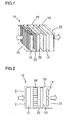
- An air purifier (10) is a household air purification system used at home or a small store, for example, and forms a dust collector according to the present invention.
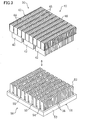
- the air purifier (10) includes a casing (20), and also includes a prefilter (11), a charging part (12), a dust collecting part (30), a catalyst filter (13), and a fan (14) that are contained in the casing (20).
- the casing (20) is formed in a rectangular, horizontally long container, for example.
- the front surface of the casing (20) forms an air inlet (21), the back surface forms an air outlet (22), and the interior forms an air passage (23).
- the prefilter (11), the charging part (12), the dust collecting part (30), the catalyst filter (13), and the fan (14) are arranged in this order from the inlet (21) toward the outlet (22).
- the prefilter (11) serves as a filter for collecting relatively large dust in the air taken through the inlet (21) into the casing (20).
- the dust collecting part (30) is designed to collect dust electrically charged at the charging part (12) by absorption.
- the dust collecting part (30) will be described later in detail.
- the catalyst filter (13) is formed with a catalyst carried on the surface of a support material having a honeycomb structure, for example.
- a catalyst carried on the surface of a support material having a honeycomb structure, for example.
- Examples of applicable catalysts include manganese catalysts and precious metal catalysts. The catalyst decomposes toxic substances and odorous substances in the air from which dust has been removed through the dust collecting part (30).
- the dust collecting part (30) includes a dust collecting electrode (40) as a first electrode, and a high-voltage electrode (50) as a second electrode.
- the dust collecting electrode (40) and the high-voltage electrode (50) are connected to a direct-current power supply, and a voltage is applied from the direct-current power supply to both of the electrodes (40, 50).
- the dust collecting electrode (40) is connected to the ground side, and the high-voltage electrode (50) is connected to the positive side of the direct-current power supply.
- the dust positively charged at the charging part (12) is collected onto the surfaces of the dust collecting electrode (40). That is, dust collecting surfaces for collecting dust in the air to be processed are formed on the surfaces of the dust collecting electrode (40).
- the dust collecting electrode (40) is made of a metal material, and, more specifically, is formed by a thin metal plate of conductive stainless spring steel.
- the high-voltage electrode (50) is made of a conductive resin material.
- the high-voltage electrode (50) is integrally formed by injection molding or the like.
- the material of the high-voltage electrode (50) is preferably a slightly conductive resin, and the volume resistivity of the resin is preferably between 10 8 ⁇ m (inclusive) and 10 13 ⁇ m (inclusive).
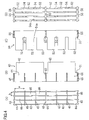
- the dust collecting electrode (40) includes a dust-collecting-side base (41) and dust-collecting-side protruding plates (42). Further, the dust-collecting-side base (41) includes a plurality of vertical partitions (44) and a plurality of horizontal partitions (45).
- the dust-collecting-side base (41) forms a base having a quadrangular grid structure, as the vertical partitions (44) and the horizontal partitions (45) are assembled together so as to be perpendicular to each other.
- rectangular grid holes (46) are defined by the vertical partitions (44) and the horizontal partitions (45).
- the aspect ratio of each of the grid holes (46) of the dust collecting electrode (40) is between 2.0 (inclusive) and 4.0 (inclusive).
- the aspect ratio indicates the ratio of a to b (a/b), where a represents the length of each grid hole (46) in the vertical direction, and b represents the length of each grid hole (46) in the horizontal direction (see FIG. 4 ).
- the plurality of dust-collecting-side protruding plates (42) are formed at the end portions in the width direction of the vertical partitions (44) of the dust-collecting-side base (41) (or in the axial direction of the grid holes (46)). That is, the dust-collecting-side protruding plates (42) form protrusions that protrude in the axial direction of the grid holes (46) from the dust-collecting-side base (41).
- the vertical partitions (44) and the dust-collecting-side protruding plates (42) form an integral single metal plate.
- Each of the dust-collecting-side protruding plates (42) is formed in a long plate-like shape that extends across three adjacent grid holes (46) of the dust-collecting-side base (41).
- each of the dust-collecting-side protruding plates (42) is formed in a long plate-like shape that extends across a plurality of grid holes (46) adjacent to one another in the same row and extends in the longitudinal direction of the vertical partitions (44) (or in the vertical direction in FIG. 4 , for example).
- three dust-collecting-side protruding plates (42) are arranged in a line for each one of the vertical partitions (44) (see FIG. 3 ).
- the high-voltage electrode (50) includes a high-voltage-side base (51) and high-voltage-side protruding plates (52). Further, the high-voltage side base (51) includes a frame (53), a plurality of vertical partitions (54), and a plurality of horizontal partitions (55). Also, in the dust collecting part (30), the dust-collecting-side base (41) is placed closer to the upstream side of the airflow in the air passage (23) than the high-voltage-side base (51) is.
- the frame (53) is formed in a rectangular shape, and the vertical partitions (54) and the horizontal partitions (55) are integrally supported in the frame (53).
- the vertical partitions (54) and the horizontal partitions (55) each have a plate-like shape, and are arranged parallel to one another at predetermined intervals.
- the thicknesses of the vertical partitions (54) and horizontal partitions (55) of the high-voltage-side base (51) are greater than the thicknesses of the vertical partitions (44) and horizontal partitions (45) of the dust-collecting-side base (41). Also, in the high-voltage-side base (51), the intervals between the vertical partitions (54) are shorter than the intervals between the horizontal partitions (55).
- the high-voltage -side base (51) forms a base having a quadrangular grid structure, as the plurality of vertical partitions (54) and the plurality of horizontal partitions (55) are assembled together so as to be perpendicular to each other.
- a plurality of grid holes (56) are defined by the vertical partitions (54) and the horizontal partitions (55).
- Each of the grid holes (56) of the high-voltage electrode (50) is formed as an elongate hole that extends in the extending direction of the dust-collecting-side protruding plates (42) (or in the vertical direction in FIG. 4 ) so as to face each corresponding one of the dust-collecting-side protruding plates (42).
- the grid holes (56) of the high-voltage electrode (50) each have a vertically long rectangular shape that extends in the longitudinal direction of the vertical partitions (54), so as to substantially correspond to each three adjacent grid holes (46, 46, 46) of the dust collecting electrode (40).
- a plurality of high-voltage-side protruding plates (52) are arranged in the longitudinal direction of the grid holes (56) at end portion (54a) of each corresponding grid hole (56).
- the high-voltage electrode (50) three high-voltage-side protruding plates (52) are arranged at predetermined intervals along each grid hole (56), and the respective high-voltage-side protruding plates (52) face the respective grid holes (46) of the dust collecting electrode (40), with a one-to-one correspondence existing between the high-voltage-side protruding plates (52) and the grid holes (46).
- the respective dust-collecting-side protruding plates (42) are inserted into the respective grid holes (56) of the high-voltage electrode (50), and the respective high-voltage-side protruding plates (52) are inserted into the respective grid holes (46) of the dust collecting electrode (40).
- the dust collecting electrode (40) and the high-voltage electrode (50) are positioned to face each other at a predetermined distance from each other so that the dust-collecting-side base (41) and the high-voltage-side base (51) do not come into contact with each other.
- the respective horizontal partitions (55) of the high-voltage electrode (50) are located substantially in the same plane as the horizontal partitions (45) of the dust collecting electrode (40).
- the high-voltage electrode (50) and the dust collecting electrode (40) are positioned so that the respective first partitions (the horizontal partitions (55)) on the short sides of the end portions (54a) of the grid holes (56) of the high-voltage electrode (50) overlap with the second partitions (the horizontal partitions (45)) parallel to the first partitions (55) at the end portions of the dust collecting electrode (40) in the axial direction of the respective grid holes (46, 56).
- the dust collecting part (30) is designed so that all the horizontal partitions (55) of the high-voltage electrode (50) invariably overlap with the horizontal partitions (45) of the dust collecting electrode (40) in the axial direction of the grid holes (46, 56) (or in the airflow direction).
- the high-voltage-side protruding plates (52) are located in a central area in the longitudinal direction of the grid holes (46) of the dust collecting electrode (40), and the dust-collecting-side protruding plates (42) are located in a central area in the longitudinal direction of the grid holes (56) of the high-voltage electrode (50).
- rectangularly cylindrical vent holes through which the air to be processed flows are formed between the inner peripheral faces of the grid holes (46) and the outer peripheral faces of the high-voltage-side protruding plates (52).
- the dust collecting part (30) having the above structure, when a potential difference is supplied between the dust collecting electrode (40) and the high-voltage electrode (50), electric fields are formed between the dust collecting electrode (40) and the high-voltage electrode (50), and dust collecting surfaces that collect dust from the air to be processed are formed on the surfaces of the dust collecting electrode (40).
- an electric field radially shaped when seen in cross section is formed between the inner peripheral face of each of the grid holes (46) and the outer peripheral face of each corresponding one of the high-voltage-side protruding plates (52).
- dust collecting surfaces (48, 48, 48, 48) for collecting positively-charged dust are formed on the inner peripheral faces of each of the grid holes (46).
- an electric field radially shaped when seen in cross section is formed between the outer peripheral face of each of the dust-collecting-side protruding plates (42) and the inner peripheral face of each corresponding one of the grid holes (56).
- dust collecting surfaces (58, 58, 58, 58) for collecting positively-charged dust are formed on the outer peripheral faces of each of the dust-collecting-side protruding plates (42).
- the operational behavior of the air purifier (10) is described. As shown in FIGS. 1 and 2 , when the fan (14) is activated, room air that is the air to be processed is drawn into the air passage (23) in the casing (20), and flows through the air passage (23). In the air i purifier (10), a direct-current voltage is applied between each pair of an ionizing wire and an facing electrode, and a direct-current voltage is applied between the dust collecting electrode (40) and the high-voltage electrode (50) of the dust collecting part (30).
- the room air drawn into the air passage (23) of the casing (20) first passes through the prefilter (11).
- the prefilter (11) collects relatively large dust in the room air.
- the room air having passed through the prefilter (11) flows into the charging part (12).
- relatively small dust having passed through the prefilter (11) is positively charged, and the positively-charged dust flows downstream.
- the positively-charged dust then flows, together with the room air, through the dust collecting part (30).
- the room air first flows into the dust-collecting-side base (41).
- the dust-collecting-side base (41) the room air flows through the vent holes of the grid holes (46).
- an electric field is formed between the inner peripheral face of each of the grid holes (46) and the outer peripheral face of each corresponding one of the high-voltage-side protruding plates (52). Therefore, the positively-charged dust is attracted and adheres to the dust collecting surfaces (48) on the inner peripheral sides of the grid holes (46). As a result, dust is removed from the room air.
- the room air flows through the vent holes of the grid holes (56).
- an electric field is formed between the inner peripheral face of each of the grid holes (56) and the outer peripheral face of each corresponding one of the dust-collecting-side protruding plates (42). Therefore, the dust remaining in the room air is attracted and adheres to the dust collecting surfaces (58) on the outer peripheries of the dust-collecting-side protruding plates (42). As a result, dust is further removed from the room air.
- the air having the dust removed in the dust collecting part (30) then flows through the catalyst filter (13).
- the catalyst filter (13) toxic substances and odorous substances in the air are decomposed/removed.
- the air cleaned in the above manner then passes through the fan (14), and is supplied into the room through the air outlet (22).
- the air purifier (10) performs the above operation to clean the room air.
- each dust-collecting-side protruding plate (82) is formed to correspond to one grid hole (86) in a dust-collecting-side base (81) having a grid structure in a dust collecting electrode (80). That is, in each vertical partition (84) of the dust-collecting-side base (81), each dust-collecting-side protruding plate (82) is formed to be located adjacent to one grid hole (86).
- a high-voltage-side base (91) having a grid structure in a high-voltage electrode (90) grid holes (96) are formed so as to correspond to the respective dust-collecting-side protruding plates (82).
- a high-voltage-side protruding plate (92) is formed so as to correspond to one grid hole (96).
- the dust collecting electrode (80) and the high-voltage electrode (90) substantially have the same structures, and the aspect ratio of each grid hole (86) of the dust collecting electrode (80) has substantially the same value as the aspect ratio of each grid hole (96) of the high-voltage electrode (90).
- the dust-collecting-side protruding plates (42) are formed across a plurality of grid holes (46) in the dust-collecting-side base (41) having the grid structure in the dust collecting electrode (40).
- the grid holes (56) each having a higher aspect ratio than that of each grid hole (46) of the dust collecting electrode (40) are formed so as to correspond to the dust-collecting-side protruding plates (42).
- the plurality of high-voltage-side protruding plates (52) are arranged at the end portions (54a) on the long sides of the grid holes (56) of the high-voltage-side base (51), so as to correspond to the respective grid holes (46) of the dust-collecting-side base (41).
- the same dust collecting surfaces as those of the dust collecting electrode (80) of the described example can be first formed on the inner peripheral surfaces of the grid holes (46) of the dust collecting electrode (40). Further, in the dust collecting electrode (40) of this embodiment, larger dust collecting faces than those of the dust collecting electrode (80) of the described example can be formed on the outer peripheral faces of the dust-collecting-side protruding plates (42).
- the intervals between the horizontal partitions (55) of the high-voltage electrode (50) are longer than the intervals between the horizontal partitions (45) of the dust collecting electrode (40), and the dust-collecting-side protruding plates (42) can be made longer in the longitudinal direction of the vertical partitions (44) by the corresponding amount. Accordingly, the areas of the outer peripheral faces of the dust-collecting-side protruding plates (42) can also be made larger.
- the number of dust-collecting-side protruding plates (42) can be made smaller than that in the comparative example. Accordingly, processing the metal plates forming the dust-collecting-side protruding plates (42) becomes easier, and the manufacturing time and costs can be reduced.
- the number of horizontal partitions (45) can be made smaller than that in the comparative example. Accordingly, the amount of resin material for forming the high-voltage electrode (50) can be made smaller, and the manufacturing costs can be reduced.
- the grid holes (56) are larger than those of the comparative example. Therefore, the resistance of the vent holes of the grid holes (56) becomes lower, and pressure loss can be reduced. Accordingly, the power for driving the fan (14) can be reduced. Also, as the grid holes (56) are made larger, dust can be prevented from being accumulated in the grid holes (56) and causing clogging.
- the dust-collecting-side base (41) is placed on the upstream side, and the high-voltage-side base (51) is placed on the downstream side. Since the dust collecting surfaces formed on the inner peripheral faces of the grid holes (46) of the dust-collecting-side base (41) have larger areas than those of the dust collecting surfaces formed on the outer peripheral faces of the dust-collecting-side protruding plates (42), dust in the room air is efficiently removed in the dust-collecting-side base (41), and the dust remaining thereafter can be efficiently removed in the high-voltage-side base (51). That is, since the dust collecting surfaces are formed in accordance with the amount of dust in the air to be processed in the dust collecting part (30), it is possible to efficiently remove dust over a long period of time.
- each of the grid holes (46) is 4 or lower in the dust collecting electrode (40), the areas of the dust collecting surfaces on the inner peripheries of the grid holes (46) become relatively large. Accordingly, the dust collecting part (30) that is small in size and has a high dust collecting efficiency can be provided. Further, since the aspect ratio is 2 or higher, the dust-collecting-side protruding plates (42) can maintain a certain strength.
- each of the dust-collecting-side protruding plates (42) is formed to extend across three adjacent grid holes (46).
- each of the dust-collecting-side protruding plates (42) may be formed to extend across two adjacent grid holes (46) or four or more adjacent grid holes (46).
- each dust-collecting-side protruding plate (42) is formed to extend across two adjacent grid holes (46).
- two high-voltage-side protruding plates (52) are arranged in the longitudinal direction at each end portion (54a) on the long sides of each grid hole (56) of the high-voltage electrode (50), so that the high-voltage-side protruding plates (52) face the respective grid holes (46) of the dust collecting electrode (40).
- the areas of the outer peripheral faces of the dust-collecting-side protruding plates (42) can be made larger, and a higher dust collecting efficiency can be achieved.
- the aspect ratio of each grid hole (56) of the high-voltage electrode (50) is almost twice higher than (or an integral multiple of) the aspect ratio of each grid hole (46) of the dust collecting electrode (40), and all the horizontal partitions (55) of the high-voltage electrode (50) overlap with the horizontal partitions (45) in the axial direction of the grid holes (46). Accordingly, in the example illustrated in FIG. 6 , the airflow resistance to the air flowing through the grid holes (46, 56) can also be lowered, and the pressure loss of the dust collecting part (30) can be reduced.
- the dust collecting electrode (40) may be made of a conductive resin material, and the high-voltage electrode (50) may be made of a metal material. Also, the charging part (12) may be designed to charge dust negatively, and the dust collecting electrode (40) may have dust collecting surfaces that collect negatively-charged dust.
Landscapes
- Electrostatic Separation (AREA)
Claims (7)
- Collecteur de poussière comprenant :une première électrode (40) qui est une électrode de collecte de poussière, et une deuxième électrode (50) qui est une électrode haute tension, dans lequel les électrodes comprennent des composants de base (41, 51), chacun ayant une structure en grille et une pluralité de parties saillantes (42, 52) qui font saillie dans un sens axial des orifices de grille (46, 56) à partir des composants de base (41, 51), respectivement, les première et deuxième électrodes (40, 50) étant positionnées de manière à se faire face l'une à l'autre, chacune des parties saillantes (42) de la première électrode (40) étant insérée dans chacun des orifices de grille correspondants (56) de la deuxième électrode (50), chacune des parties saillantes (52) de la deuxième électrode (50) étant insérée dans chacun des orifices de grille correspondants (46) de la première électrode (40), des surfaces de collecte de poussière pour collecter la poussière d'un air à traiter étant formées sur les surfaces de la première électrode (40),caractérisé en ce quechacune des parties saillantes (42) de la première électrode (40) est réalisée en une forme analogue à une longue plaque s'étendant à travers une pluralité d'orifices de grille adjacents des orifices de grille (46) de la première électrode (40),chacun des orifices de grille (56) de la deuxième électrode (50) est réalisé en forme d'orifice allongé s'étendant pour correspondre à chacune des parties saillantes correspondantes (42) de la première électrode (40), etles parties saillantes (52) de la deuxième électrode (50) sont agencées dans un sens longitudinal au niveau des parties d'extrémité (54a) sur les côtés longs des orifices de grille (56) de la deuxième électrode (50) pour correspondre aux orifices de grille respectifs (46) de la première électrode (40).
- Collecteur de poussière selon la revendication 1, dans lequel chacune des parties saillantes (42) de la première électrode (40) est réalisée en une forme analogue à une longue plaque s'étendant à travers trois ou plus orifices de grille des orifices de grille (46) de la première électrode (40).
- Collecteur de poussière selon la revendication 1 ou 2, dans lequel
la première électrode (40) et la deuxième électrode (50) sont positionnées de sorte à ce que des premières cloisons respectives (55) formant les côtés courts des parties d'extrémité (54a) des orifices de grille respectifs (56) de la deuxième électrode (50) se chevauchent avec les deuxièmes cloisons (45) des parties d'extrémité des orifices de grille (46) de la première électrode (40) dans le sens axial des orifices de grille (46, 56), les deuxièmes cloisons (45) étant parallèles aux premières cloisons (55). - Collecteur de poussière selon l'une quelconque des revendications 1 à 3, dans lequel
la deuxième électrode (50) est réalisée en un matériau de résine conducteur. - Collecteur de poussière selon l'une quelconque des revendications 1 à 4, dans lequel
la première électrode (40) est réalisée en un matériau métallique. - Collecteur de poussière selon l'une quelconque des revendications 1 à 5, dans lequel
le composant de base (41) de la première électrode (40) est situé plus près d'un côté d'amenée d'un flux de l'air à traiter que le compostant de base (51) de la deuxième électrode (50). - Collecteur de poussière selon l'une quelconque des revendications 1 à 6 dans lequel
un rapport d'aspect de chacun des orifices de grille (46) de la première électrode (40) est de 4 ou inférieur.
Applications Claiming Priority (2)
| Application Number | Priority Date | Filing Date | Title |
|---|---|---|---|
| JP2008292023 | 2008-11-14 | ||
| PCT/JP2009/004181 WO2010055600A1 (fr) | 2008-11-14 | 2009-08-27 | Dispositif de collecte de poussière |
Publications (3)
| Publication Number | Publication Date |
|---|---|
| EP2347829A1 EP2347829A1 (fr) | 2011-07-27 |
| EP2347829A4 EP2347829A4 (fr) | 2013-10-16 |
| EP2347829B1 true EP2347829B1 (fr) | 2014-10-29 |
Family
ID=42169747
Family Applications (1)
| Application Number | Title | Priority Date | Filing Date |
|---|---|---|---|
| EP09825855.1A Not-in-force EP2347829B1 (fr) | 2008-11-14 | 2009-08-27 | Dispositif de collecte de poussiere |
Country Status (8)
| Country | Link |
|---|---|
| US (1) | US8657937B2 (fr) |
| EP (1) | EP2347829B1 (fr) |
| JP (1) | JP4462385B1 (fr) |
| KR (1) | KR101206572B1 (fr) |
| CN (1) | CN102209591B (fr) |
| AU (1) | AU2009315189B2 (fr) |
| ES (1) | ES2523674T3 (fr) |
| WO (1) | WO2010055600A1 (fr) |
Cited By (1)
| Publication number | Priority date | Publication date | Assignee | Title |
|---|---|---|---|---|
| EP3677338B1 (fr) * | 2017-09-01 | 2023-06-07 | Suzhou Beiang Technology Ltd. | Noyau de purification séparable facile à nettoyer |
Families Citing this family (12)
| Publication number | Priority date | Publication date | Assignee | Title |
|---|---|---|---|---|
| CN103691557A (zh) * | 2014-01-03 | 2014-04-02 | 常州市伟泰电子科技有限公司 | 电离型空气净化器的静电吸附单元 |
| CN104259000B (zh) * | 2014-08-19 | 2017-05-24 | 阮海生 | 一种介电电泳净化处理装置 |
| WO2016050218A2 (fr) * | 2014-09-30 | 2016-04-07 | 广东美的制冷设备有限公司 | Ensemble dépoussiéreur, dispositif de purification d'air et climatiseur |
| KR101953492B1 (ko) * | 2014-09-30 | 2019-02-28 | 지디 미디어 에어콘디셔닝 이큅먼트 씨오 엘티디 | 집진 어셈블리, 공기 정화 장치 및 에어컨 |
| KR102201298B1 (ko) * | 2015-02-17 | 2021-01-11 | 한온시스템 주식회사 | 전기집진용 대전장치 |
| CN105363557B (zh) * | 2015-12-03 | 2017-08-15 | 宁波哲恺电器有限公司 | 静电集尘模块及其静电式空气净化器 |
| WO2019132554A1 (fr) * | 2017-12-27 | 2019-07-04 | Samsung Electronics Co., Ltd. | Appareil de charge et précipitateur |
| DE102018220720A1 (de) * | 2018-11-30 | 2020-06-04 | BSH Hausgeräte GmbH | Elektrostatisches Filtermodul für Luftreiniger und Luftreiniger |
| DE102019203032A1 (de) * | 2019-03-06 | 2020-09-10 | BSH Hausgeräte GmbH | Elektrostatische Filtereinheit für Luftreinigungsvorrichtung und Luftreinigungsvorrichtung |
| KR102230251B1 (ko) * | 2019-07-10 | 2021-03-18 | 신찬수 | 전력선의 고전압을 이용한 대기 중 미세먼지 집진장치 |
| DE102019216344A1 (de) * | 2019-10-23 | 2021-04-29 | BSH Hausgeräte GmbH | Elektrostatische Filtereinheit für Luftreinigungsvorrichtung und Luftreinigungsvorrichtung |
| DE102019217832A1 (de) * | 2019-11-19 | 2021-05-20 | BSH Hausgeräte GmbH | Elektrostatische Filtereinheit für Luftreinigungsvorrichtung und Luftreinigungsvorrichtung |
Family Cites Families (21)
| Publication number | Priority date | Publication date | Assignee | Title |
|---|---|---|---|---|
| US3678653A (en) * | 1970-05-11 | 1972-07-25 | Elmer W Buschman | Electrostatic precipitator |
| JP3143144B2 (ja) * | 1991-06-07 | 2001-03-07 | 三洋電機株式会社 | エアーフィルター装置 |
| KR930017626A (ko) * | 1992-02-28 | 1993-09-20 | 강진구 | 전기집진기 |
| TW332802B (en) * | 1992-06-04 | 1998-06-01 | Nippon Denso Co | The air purifier |
| IT1264824B1 (it) * | 1993-07-28 | 1996-10-10 | Luigi Bontempi | Filtro elettrostatico bistadio ad elementi estrusifiltro elettrostatico bistadio ad elementi estrusi modulari particolarmente per apparecchiature di modulari particolarmente per apparecchiature di ricircolo dell'aria ricircolo dell'aria |
| SE515908C2 (sv) * | 1995-02-08 | 2001-10-29 | Purocell Sa | Anordning vid elektrostatfilter |
| US5622543A (en) * | 1995-09-20 | 1997-04-22 | Yang; Chen-Ho | Rectilinear turbulent flow type air purifier |
| US5820660A (en) * | 1997-07-29 | 1998-10-13 | Ko; Li-Sheng | Air cleaner having improved dust collector |
| US6126727A (en) * | 1999-01-28 | 2000-10-03 | Lo; Ching-Hsiang | Electrode panel-drawing device of a static ion discharger |
| JP3287468B2 (ja) * | 1999-11-15 | 2002-06-04 | 株式会社オーデン | 電気集塵ユニット |
| JP4362001B2 (ja) * | 2000-03-31 | 2009-11-11 | ミドリ安全株式会社 | 空気清浄装置 |
| CN2463052Y (zh) * | 2000-12-02 | 2001-12-05 | 海尔集团公司 | 空调室内机的高压集尘器 |
| GB0408910D0 (en) * | 2004-04-22 | 2004-05-26 | Darwin Technology Ltd | Device for air cleaning |
| JP4562729B2 (ja) | 2004-05-28 | 2010-10-13 | ミドリ安全株式会社 | 電極および電気集塵機 |
| WO2005115628A1 (fr) | 2004-05-28 | 2005-12-08 | Midori Anzen Co., Ltd. | Electrode et collecteur de salete electrique |
| US7258715B2 (en) * | 2004-07-22 | 2007-08-21 | Kaz, Incorporated | Air cleaner |
| JP2008018425A (ja) | 2006-06-15 | 2008-01-31 | Daikin Ind Ltd | 集塵装置 |
| KR101082713B1 (ko) * | 2006-06-15 | 2011-11-15 | 다이킨 고교 가부시키가이샤 | 집진장치 |
| CN101472682B (zh) * | 2006-06-15 | 2012-05-09 | 大金工业株式会社 | 集尘装置 |
| JP2009082912A (ja) | 2007-09-11 | 2009-04-23 | Daikin Ind Ltd | 集塵装置 |
| JP2009214048A (ja) | 2008-03-11 | 2009-09-24 | Daikin Ind Ltd | 集塵装置 |
-
2009
- 2009-08-27 ES ES09825855.1T patent/ES2523674T3/es active Active
- 2009-08-27 JP JP2009196457A patent/JP4462385B1/ja active Active
- 2009-08-27 AU AU2009315189A patent/AU2009315189B2/en not_active Ceased
- 2009-08-27 WO PCT/JP2009/004181 patent/WO2010055600A1/fr not_active Ceased
- 2009-08-27 EP EP09825855.1A patent/EP2347829B1/fr not_active Not-in-force
- 2009-08-27 KR KR1020117013533A patent/KR101206572B1/ko not_active Expired - Fee Related
- 2009-08-27 US US13/125,166 patent/US8657937B2/en not_active Expired - Fee Related
- 2009-08-27 CN CN2009801454244A patent/CN102209591B/zh active Active
Cited By (1)
| Publication number | Priority date | Publication date | Assignee | Title |
|---|---|---|---|---|
| EP3677338B1 (fr) * | 2017-09-01 | 2023-06-07 | Suzhou Beiang Technology Ltd. | Noyau de purification séparable facile à nettoyer |
Also Published As
| Publication number | Publication date |
|---|---|
| KR101206572B1 (ko) | 2012-11-30 |
| US8657937B2 (en) | 2014-02-25 |
| JP2010137218A (ja) | 2010-06-24 |
| CN102209591A (zh) | 2011-10-05 |
| EP2347829A1 (fr) | 2011-07-27 |
| AU2009315189A1 (en) | 2010-05-20 |
| US20110197768A1 (en) | 2011-08-18 |
| EP2347829A4 (fr) | 2013-10-16 |
| AU2009315189B2 (en) | 2012-09-20 |
| CN102209591B (zh) | 2013-07-03 |
| JP4462385B1 (ja) | 2010-05-12 |
| WO2010055600A1 (fr) | 2010-05-20 |
| KR20110095329A (ko) | 2011-08-24 |
| ES2523674T3 (es) | 2014-11-28 |
Similar Documents
| Publication | Publication Date | Title |
|---|---|---|
| EP2347829B1 (fr) | Dispositif de collecte de poussiere | |
| AU664069B2 (en) | Electrical dust collector | |
| EP2039432B1 (fr) | Collecteur de poussiere | |
| US9795971B2 (en) | Semi-enclosed air cleaner used in an air-conditioner | |
| CN104994960A (zh) | 集尘器、集尘系统,及集尘方法 | |
| KR101651034B1 (ko) | 전기집진기 및 그 전기집진기를 포함하는 공기청정 시스템 | |
| US8192536B2 (en) | Dust collector | |
| CN104971823A (zh) | 一种便于清洗的空气集尘设备及具有该设备的空气净化器 | |
| JP7665368B2 (ja) | 荷電装置及び空気清浄機 | |
| CN107649291B (zh) | 除尘组件及具有其的空气处理设备 | |
| KR100722863B1 (ko) | 전기 집진기의 콜렉터 셀 유니트 | |
| KR20070095406A (ko) | 공기정화장치 | |
| CN213314177U (zh) | 一种无纺布生产专用烟气净化器 | |
| EP3476456A1 (fr) | Filtre de purification d'air amélioré | |
| CN217190197U (zh) | 一种使颗粒物带电荷的过滤器 | |
| CN216173231U (zh) | 电净化装置及空气净化设备 | |
| CN111992335A (zh) | 用于过滤空气中细微颗粒物的高压集尘装置及集尘系统 | |
| CN213480514U (zh) | 电净化组件、空气净化设备 | |
| WO2004067183A1 (fr) | Depoussiereur electrique | |
| CN113877729A (zh) | 电净化装置及空气净化设备 | |
| CN105716171B (zh) | 高效静电式光催化空气净化装置 | |
| WO2020245508A1 (fr) | Module purificateur d'air, système de purification d'air, unité de traitement d'air, utilisation d'un module purificateur d'air et procédé de purification d'air | |
| CN218078402U (zh) | 静电集尘模块和具有其的空气处理装置 | |
| CN223875239U (zh) | 一种静电除尘装置及空气清洁设备 | |
| JP4835288B2 (ja) | 電気集塵装置及び集塵モジュール |
Legal Events
| Date | Code | Title | Description |
|---|---|---|---|
| PUAI | Public reference made under article 153(3) epc to a published international application that has entered the european phase |
Free format text: ORIGINAL CODE: 0009012 |
|
| 17P | Request for examination filed |
Effective date: 20110420 |
|
| AK | Designated contracting states |
Kind code of ref document: A1 Designated state(s): AT BE BG CH CY CZ DE DK EE ES FI FR GB GR HR HU IE IS IT LI LT LU LV MC MK MT NL NO PL PT RO SE SI SK SM TR |
|
| AX | Request for extension of the european patent |
Extension state: AL BA RS |
|
| DAX | Request for extension of the european patent (deleted) | ||
| A4 | Supplementary search report drawn up and despatched |
Effective date: 20130912 |
|
| RIC1 | Information provided on ipc code assigned before grant |
Ipc: B03C 3/011 20060101ALN20130906BHEP Ipc: B03C 3/64 20060101ALN20130906BHEP Ipc: B03C 3/40 20060101ALI20130906BHEP Ipc: B03C 3/47 20060101AFI20130906BHEP Ipc: B03C 3/155 20060101ALN20130906BHEP Ipc: B03C 3/45 20060101ALN20130906BHEP |
|
| REG | Reference to a national code |
Ref country code: DE Ref legal event code: R079 Ref document number: 602009027501 Country of ref document: DE Free format text: PREVIOUS MAIN CLASS: B03C0003400000 Ipc: B03C0003470000 |
|
| GRAP | Despatch of communication of intention to grant a patent |
Free format text: ORIGINAL CODE: EPIDOSNIGR1 |
|
| RIC1 | Information provided on ipc code assigned before grant |
Ipc: B03C 3/47 20060101AFI20140702BHEP Ipc: B03C 3/155 20060101ALN20140702BHEP Ipc: B03C 3/64 20060101ALN20140702BHEP Ipc: B03C 3/08 20060101ALN20140702BHEP Ipc: B03C 3/011 20060101ALN20140702BHEP Ipc: B03C 3/45 20060101ALN20140702BHEP Ipc: B03C 3/40 20060101ALI20140702BHEP |
|
| INTG | Intention to grant announced |
Effective date: 20140725 |
|
| GRAS | Grant fee paid |
Free format text: ORIGINAL CODE: EPIDOSNIGR3 |
|
| GRAA | (expected) grant |
Free format text: ORIGINAL CODE: 0009210 |
|
| AK | Designated contracting states |
Kind code of ref document: B1 Designated state(s): AT BE BG CH CY CZ DE DK EE ES FI FR GB GR HR HU IE IS IT LI LT LU LV MC MK MT NL NO PL PT RO SE SI SK SM TR |
|
| REG | Reference to a national code |
Ref country code: GB Ref legal event code: FG4D |
|
| REG | Reference to a national code |
Ref country code: CH Ref legal event code: EP |
|
| REG | Reference to a national code |
Ref country code: AT Ref legal event code: REF Ref document number: 693285 Country of ref document: AT Kind code of ref document: T Effective date: 20141115 |
|
| REG | Reference to a national code |
Ref country code: IE Ref legal event code: FG4D |
|
| REG | Reference to a national code |
Ref country code: ES Ref legal event code: FG2A Ref document number: 2523674 Country of ref document: ES Kind code of ref document: T3 Effective date: 20141128 |
|
| REG | Reference to a national code |
Ref country code: DE Ref legal event code: R096 Ref document number: 602009027501 Country of ref document: DE Effective date: 20141211 |
|
| REG | Reference to a national code |
Ref country code: AT Ref legal event code: MK05 Ref document number: 693285 Country of ref document: AT Kind code of ref document: T Effective date: 20141029 |
|
| REG | Reference to a national code |
Ref country code: NL Ref legal event code: VDEP Effective date: 20141029 |
|
| REG | Reference to a national code |
Ref country code: LT Ref legal event code: MG4D |
|
| PG25 | Lapsed in a contracting state [announced via postgrant information from national office to epo] |
Ref country code: IS Free format text: LAPSE BECAUSE OF FAILURE TO SUBMIT A TRANSLATION OF THE DESCRIPTION OR TO PAY THE FEE WITHIN THE PRESCRIBED TIME-LIMIT Effective date: 20150228 Ref country code: NO Free format text: LAPSE BECAUSE OF FAILURE TO SUBMIT A TRANSLATION OF THE DESCRIPTION OR TO PAY THE FEE WITHIN THE PRESCRIBED TIME-LIMIT Effective date: 20150129 Ref country code: NL Free format text: LAPSE BECAUSE OF FAILURE TO SUBMIT A TRANSLATION OF THE DESCRIPTION OR TO PAY THE FEE WITHIN THE PRESCRIBED TIME-LIMIT Effective date: 20141029 Ref country code: PT Free format text: LAPSE BECAUSE OF FAILURE TO SUBMIT A TRANSLATION OF THE DESCRIPTION OR TO PAY THE FEE WITHIN THE PRESCRIBED TIME-LIMIT Effective date: 20150302 Ref country code: LT Free format text: LAPSE BECAUSE OF FAILURE TO SUBMIT A TRANSLATION OF THE DESCRIPTION OR TO PAY THE FEE WITHIN THE PRESCRIBED TIME-LIMIT Effective date: 20141029 Ref country code: FI Free format text: LAPSE BECAUSE OF FAILURE TO SUBMIT A TRANSLATION OF THE DESCRIPTION OR TO PAY THE FEE WITHIN THE PRESCRIBED TIME-LIMIT Effective date: 20141029 |
|
| PG25 | Lapsed in a contracting state [announced via postgrant information from national office to epo] |
Ref country code: LV Free format text: LAPSE BECAUSE OF FAILURE TO SUBMIT A TRANSLATION OF THE DESCRIPTION OR TO PAY THE FEE WITHIN THE PRESCRIBED TIME-LIMIT Effective date: 20141029 Ref country code: GR Free format text: LAPSE BECAUSE OF FAILURE TO SUBMIT A TRANSLATION OF THE DESCRIPTION OR TO PAY THE FEE WITHIN THE PRESCRIBED TIME-LIMIT Effective date: 20150130 Ref country code: AT Free format text: LAPSE BECAUSE OF FAILURE TO SUBMIT A TRANSLATION OF THE DESCRIPTION OR TO PAY THE FEE WITHIN THE PRESCRIBED TIME-LIMIT Effective date: 20141029 Ref country code: SE Free format text: LAPSE BECAUSE OF FAILURE TO SUBMIT A TRANSLATION OF THE DESCRIPTION OR TO PAY THE FEE WITHIN THE PRESCRIBED TIME-LIMIT Effective date: 20141029 Ref country code: PL Free format text: LAPSE BECAUSE OF FAILURE TO SUBMIT A TRANSLATION OF THE DESCRIPTION OR TO PAY THE FEE WITHIN THE PRESCRIBED TIME-LIMIT Effective date: 20141029 Ref country code: HR Free format text: LAPSE BECAUSE OF FAILURE TO SUBMIT A TRANSLATION OF THE DESCRIPTION OR TO PAY THE FEE WITHIN THE PRESCRIBED TIME-LIMIT Effective date: 20141029 Ref country code: CY Free format text: LAPSE BECAUSE OF FAILURE TO SUBMIT A TRANSLATION OF THE DESCRIPTION OR TO PAY THE FEE WITHIN THE PRESCRIBED TIME-LIMIT Effective date: 20141029 |
|
| REG | Reference to a national code |
Ref country code: DE Ref legal event code: R097 Ref document number: 602009027501 Country of ref document: DE |
|
| PG25 | Lapsed in a contracting state [announced via postgrant information from national office to epo] |
Ref country code: CZ Free format text: LAPSE BECAUSE OF FAILURE TO SUBMIT A TRANSLATION OF THE DESCRIPTION OR TO PAY THE FEE WITHIN THE PRESCRIBED TIME-LIMIT Effective date: 20141029 Ref country code: EE Free format text: LAPSE BECAUSE OF FAILURE TO SUBMIT A TRANSLATION OF THE DESCRIPTION OR TO PAY THE FEE WITHIN THE PRESCRIBED TIME-LIMIT Effective date: 20141029 Ref country code: DK Free format text: LAPSE BECAUSE OF FAILURE TO SUBMIT A TRANSLATION OF THE DESCRIPTION OR TO PAY THE FEE WITHIN THE PRESCRIBED TIME-LIMIT Effective date: 20141029 Ref country code: RO Free format text: LAPSE BECAUSE OF FAILURE TO SUBMIT A TRANSLATION OF THE DESCRIPTION OR TO PAY THE FEE WITHIN THE PRESCRIBED TIME-LIMIT Effective date: 20141029 Ref country code: SK Free format text: LAPSE BECAUSE OF FAILURE TO SUBMIT A TRANSLATION OF THE DESCRIPTION OR TO PAY THE FEE WITHIN THE PRESCRIBED TIME-LIMIT Effective date: 20141029 |
|
| PLBE | No opposition filed within time limit |
Free format text: ORIGINAL CODE: 0009261 |
|
| STAA | Information on the status of an ep patent application or granted ep patent |
Free format text: STATUS: NO OPPOSITION FILED WITHIN TIME LIMIT |
|
| 26N | No opposition filed |
Effective date: 20150730 |
|
| PG25 | Lapsed in a contracting state [announced via postgrant information from national office to epo] |
Ref country code: SI Free format text: LAPSE BECAUSE OF FAILURE TO SUBMIT A TRANSLATION OF THE DESCRIPTION OR TO PAY THE FEE WITHIN THE PRESCRIBED TIME-LIMIT Effective date: 20141029 |
|
| PG25 | Lapsed in a contracting state [announced via postgrant information from national office to epo] |
Ref country code: MC Free format text: LAPSE BECAUSE OF FAILURE TO SUBMIT A TRANSLATION OF THE DESCRIPTION OR TO PAY THE FEE WITHIN THE PRESCRIBED TIME-LIMIT Effective date: 20141029 Ref country code: LU Free format text: LAPSE BECAUSE OF FAILURE TO SUBMIT A TRANSLATION OF THE DESCRIPTION OR TO PAY THE FEE WITHIN THE PRESCRIBED TIME-LIMIT Effective date: 20150827 |
|
| REG | Reference to a national code |
Ref country code: CH Ref legal event code: PL |
|
| PG25 | Lapsed in a contracting state [announced via postgrant information from national office to epo] |
Ref country code: CH Free format text: LAPSE BECAUSE OF NON-PAYMENT OF DUE FEES Effective date: 20150831 Ref country code: LI Free format text: LAPSE BECAUSE OF NON-PAYMENT OF DUE FEES Effective date: 20150831 |
|
| REG | Reference to a national code |
Ref country code: IE Ref legal event code: MM4A |
|
| REG | Reference to a national code |
Ref country code: FR Ref legal event code: PLFP Year of fee payment: 8 |
|
| PG25 | Lapsed in a contracting state [announced via postgrant information from national office to epo] |
Ref country code: IE Free format text: LAPSE BECAUSE OF NON-PAYMENT OF DUE FEES Effective date: 20150827 |
|
| PGFP | Annual fee paid to national office [announced via postgrant information from national office to epo] |
Ref country code: GB Payment date: 20160824 Year of fee payment: 8 Ref country code: IT Payment date: 20160822 Year of fee payment: 8 Ref country code: DE Payment date: 20160823 Year of fee payment: 8 |
|
| PGFP | Annual fee paid to national office [announced via postgrant information from national office to epo] |
Ref country code: FR Payment date: 20160712 Year of fee payment: 8 |
|
| PGFP | Annual fee paid to national office [announced via postgrant information from national office to epo] |
Ref country code: ES Payment date: 20160712 Year of fee payment: 8 |
|
| PG25 | Lapsed in a contracting state [announced via postgrant information from national office to epo] |
Ref country code: MT Free format text: LAPSE BECAUSE OF FAILURE TO SUBMIT A TRANSLATION OF THE DESCRIPTION OR TO PAY THE FEE WITHIN THE PRESCRIBED TIME-LIMIT Effective date: 20141029 |
|
| PG25 | Lapsed in a contracting state [announced via postgrant information from national office to epo] |
Ref country code: BG Free format text: LAPSE BECAUSE OF FAILURE TO SUBMIT A TRANSLATION OF THE DESCRIPTION OR TO PAY THE FEE WITHIN THE PRESCRIBED TIME-LIMIT Effective date: 20141029 Ref country code: HU Free format text: LAPSE BECAUSE OF FAILURE TO SUBMIT A TRANSLATION OF THE DESCRIPTION OR TO PAY THE FEE WITHIN THE PRESCRIBED TIME-LIMIT; INVALID AB INITIO Effective date: 20090827 Ref country code: SM Free format text: LAPSE BECAUSE OF FAILURE TO SUBMIT A TRANSLATION OF THE DESCRIPTION OR TO PAY THE FEE WITHIN THE PRESCRIBED TIME-LIMIT Effective date: 20141029 |
|
| PG25 | Lapsed in a contracting state [announced via postgrant information from national office to epo] |
Ref country code: TR Free format text: LAPSE BECAUSE OF FAILURE TO SUBMIT A TRANSLATION OF THE DESCRIPTION OR TO PAY THE FEE WITHIN THE PRESCRIBED TIME-LIMIT Effective date: 20141029 |
|
| PG25 | Lapsed in a contracting state [announced via postgrant information from national office to epo] |
Ref country code: BE Free format text: LAPSE BECAUSE OF FAILURE TO SUBMIT A TRANSLATION OF THE DESCRIPTION OR TO PAY THE FEE WITHIN THE PRESCRIBED TIME-LIMIT Effective date: 20141029 |
|
| REG | Reference to a national code |
Ref country code: DE Ref legal event code: R119 Ref document number: 602009027501 Country of ref document: DE |
|
| GBPC | Gb: european patent ceased through non-payment of renewal fee |
Effective date: 20170827 |
|
| REG | Reference to a national code |
Ref country code: FR Ref legal event code: ST Effective date: 20180430 |
|
| PG25 | Lapsed in a contracting state [announced via postgrant information from national office to epo] |
Ref country code: MK Free format text: LAPSE BECAUSE OF FAILURE TO SUBMIT A TRANSLATION OF THE DESCRIPTION OR TO PAY THE FEE WITHIN THE PRESCRIBED TIME-LIMIT Effective date: 20141029 |
|
| PG25 | Lapsed in a contracting state [announced via postgrant information from national office to epo] |
Ref country code: GB Free format text: LAPSE BECAUSE OF NON-PAYMENT OF DUE FEES Effective date: 20170827 Ref country code: DE Free format text: LAPSE BECAUSE OF NON-PAYMENT OF DUE FEES Effective date: 20180301 |
|
| PG25 | Lapsed in a contracting state [announced via postgrant information from national office to epo] |
Ref country code: IT Free format text: LAPSE BECAUSE OF NON-PAYMENT OF DUE FEES Effective date: 20170827 Ref country code: FR Free format text: LAPSE BECAUSE OF NON-PAYMENT OF DUE FEES Effective date: 20170831 |
|
| REG | Reference to a national code |
Ref country code: ES Ref legal event code: FD2A Effective date: 20181025 |
|
| PG25 | Lapsed in a contracting state [announced via postgrant information from national office to epo] |
Ref country code: ES Free format text: LAPSE BECAUSE OF NON-PAYMENT OF DUE FEES Effective date: 20170828 |