EP2347865A1 - Outil électrique - Google Patents
Outil électrique Download PDFInfo
- Publication number
- EP2347865A1 EP2347865A1 EP10196699A EP10196699A EP2347865A1 EP 2347865 A1 EP2347865 A1 EP 2347865A1 EP 10196699 A EP10196699 A EP 10196699A EP 10196699 A EP10196699 A EP 10196699A EP 2347865 A1 EP2347865 A1 EP 2347865A1
- Authority
- EP
- European Patent Office
- Prior art keywords
- drive
- coupling
- axis
- rotation
- drive gear
- Prior art date
- Legal status (The legal status is an assumption and is not a legal conclusion. Google has not performed a legal analysis and makes no representation as to the accuracy of the status listed.)
- Granted
Links
- 230000008878 coupling Effects 0.000 claims abstract description 76
- 238000010168 coupling process Methods 0.000 claims abstract description 76
- 238000005859 coupling reaction Methods 0.000 claims abstract description 76
- 238000009527 percussion Methods 0.000 claims abstract description 24
- 230000003213 activating effect Effects 0.000 claims abstract description 4
- 230000000295 complement effect Effects 0.000 claims description 11
- 230000005540 biological transmission Effects 0.000 claims description 7
- 230000001419 dependent effect Effects 0.000 description 2
- 230000010354 integration Effects 0.000 description 2
- 238000010276 construction Methods 0.000 description 1
- 238000005553 drilling Methods 0.000 description 1
- 238000002347 injection Methods 0.000 description 1
- 239000007924 injection Substances 0.000 description 1
- 238000009434 installation Methods 0.000 description 1
- 238000002955 isolation Methods 0.000 description 1
- 239000002184 metal Substances 0.000 description 1
Images


Classifications
-
- B—PERFORMING OPERATIONS; TRANSPORTING
- B25—HAND TOOLS; PORTABLE POWER-DRIVEN TOOLS; MANIPULATORS
- B25D—PERCUSSIVE TOOLS
- B25D16/00—Portable percussive machines with superimposed rotation, the rotational movement of the output shaft of a motor being modified to generate axial impacts on the tool bit
- B25D16/006—Mode changers; Mechanisms connected thereto
-
- B—PERFORMING OPERATIONS; TRANSPORTING
- B25—HAND TOOLS; PORTABLE POWER-DRIVEN TOOLS; MANIPULATORS
- B25D—PERCUSSIVE TOOLS
- B25D2211/00—Details of portable percussive tools with electromotor or other motor drive
- B25D2211/003—Crossed drill and motor spindles
-
- B—PERFORMING OPERATIONS; TRANSPORTING
- B25—HAND TOOLS; PORTABLE POWER-DRIVEN TOOLS; MANIPULATORS
- B25D—PERCUSSIVE TOOLS
- B25D2211/00—Details of portable percussive tools with electromotor or other motor drive
- B25D2211/06—Means for driving the impulse member
- B25D2211/068—Crank-actuated impulse-driving mechanisms
-
- B—PERFORMING OPERATIONS; TRANSPORTING
- B25—HAND TOOLS; PORTABLE POWER-DRIVEN TOOLS; MANIPULATORS
- B25D—PERCUSSIVE TOOLS
- B25D2216/00—Details of portable percussive machines with superimposed rotation, the rotational movement of the output shaft of a motor being modified to generate axial impacts on the tool bit
- B25D2216/0007—Details of percussion or rotation modes
- B25D2216/0023—Tools having a percussion-and-rotation mode
-
- B—PERFORMING OPERATIONS; TRANSPORTING
- B25—HAND TOOLS; PORTABLE POWER-DRIVEN TOOLS; MANIPULATORS
- B25D—PERCUSSIVE TOOLS
- B25D2216/00—Details of portable percussive machines with superimposed rotation, the rotational movement of the output shaft of a motor being modified to generate axial impacts on the tool bit
- B25D2216/0007—Details of percussion or rotation modes
- B25D2216/0038—Tools having a rotation-only mode
-
- B—PERFORMING OPERATIONS; TRANSPORTING
- B25—HAND TOOLS; PORTABLE POWER-DRIVEN TOOLS; MANIPULATORS
- B25D—PERCUSSIVE TOOLS
- B25D2250/00—General details of portable percussive tools; Components used in portable percussive tools
- B25D2250/165—Overload clutches, torque limiters
-
- B—PERFORMING OPERATIONS; TRANSPORTING
- B25—HAND TOOLS; PORTABLE POWER-DRIVEN TOOLS; MANIPULATORS
- B25D—PERCUSSIVE TOOLS
- B25D2250/00—General details of portable percussive tools; Components used in portable percussive tools
- B25D2250/245—Spatial arrangement of components of the tool relative to each other
Definitions
- the present invention relates to a power tool, in particular a manually operable power tool, preferably a hammer drill.
- a power tool such as a hammer drill
- a power tool includes a drive motor, a tool spindle for rotationally driving a tool, a rotary drive gear for coupling the drive motor to the tool spindle, a hammer mechanism for hammering the tool, a hammer mechanism for coupling the drive motor to the hammer mechanism, and a switching device for activating and deactivating the striking mechanism.
- the present invention is concerned with the problem of providing for such a power tool an improved or at least another embodiment, which is characterized in particular by a compact design.
- the invention is based on the general idea to equip the switching device with a clutch which is integrated into the force path of the percussion gear and which has an actuating stroke for engagement and disengagement, ie for activating and deactivating the impact mechanism.
- the switching device is designed such that a stroke direction of this actuating stroke extends transversely to the axis of rotation of the tool spindle or parallel to a rotational axis of a manually rotatable actuatable element of the switching device extends.
- the actuating stroke can extend both transversely to the axis of rotation of the tool spindle and parallel to the axis of rotation of the actuating element.
- the actuating stroke of the clutch corresponds to a linear adjustment movement of a corresponding coupling member, which causes the engagement or disengagement of the clutch.
- the orientation of the actuating stroke transverse to the axis of rotation of the tool spindle or parallel to the axis of rotation of the actuating element and the integration of the coupling in the percussion gear allows a spatially close arrangement of the switching device on the tool spindle, which can be a total of a compact structure for the power tool to realize.
- the coupling can be particularly easily integrated into the force path of the percussion gear when the percussion gear has an input-side drive gear which is rotatably mounted about a rotation axis, and if the percussion gear has an output side crank drive, which is rotatably mounted about the axis of rotation of the drive gear is and activates impactor a connecting rod of the percussion mechanism.
- the clutch comprises in the hammer mechanism a coupling ring which is arranged coaxially to the axis of rotation of the drive gear on the crank gear and is arranged axially adjustable and rotationally fixed on the crank drive.
- this coupling ring interacts with the drive gear, such that the coupling ring transmits torque from the drive gear to the crank gear in the engaged state, while in the disengaged state no torque transmission from the drive gear via the coupling ring to the crank drive.
- the design presented here leads to a particularly compact integration of the clutch in the percussion gearbox.
- the drive gear can have a driver contour on an axial side facing the crank gear, while the coupling ring has a driver contour complementary to the driver gear of the drive gear, which interacts with the driver contour of the drive gear in the engaged state of the clutch ring for torque transmission and in the disengaged state it is released axially.
- the axial Mit Anlagenkonturen can transmit large torques and require little installation space.
- the switching device has an actuating device for engagement and disengagement of the coupling, which couples a manually operable actuating element with an adjustable coupling member of the clutch.
- the coupling member is expediently the coupling ring.
- the actuating element which is preferably arranged on the outside of a housing of the power tool, makes it possible to engage in the percussion gear mechanism or in the clutch in order to engage or disengage it.
- the actuating device may be equipped with a lifting element which is coupled via at least one parallel to the axis of rotation of the drive gear arm portion with the coupling ring, so that a direction away from the drive gear stroke adjustment of the lifting element parallel to the axis of rotation of the drive gear entrains the clutch ring and disengages.
- the actuating device engages with the respective arm portion of the lifting element, the crank drive wheel to come into engagement with the coupling ring. This allows a particularly space-saving arrangement of the actuator coaxial with the axis of rotation of the drive gear.
- to realize a rotationally fixed and axially adjustable coupling between the coupling ring and the crank drive be provided to equip the crank drive in an axial section with an outer driver contour and to provide the coupling ring with a complementary inner driver contour, so that the Coupling ring on these Mitêturgituren rotationally fixed and axially adjustable is arranged on the crank drive wheel.
- Particularly expedient is a development in which the driver contours are designed as polygonal profiles. These allow a particularly high torque transmission with low wear.
- the proposed construction allows a particularly compact design with high reliability.
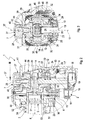
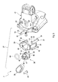
- Corresponding Fig. 1 includes a power tool 1, which is manually operable and is configured in the example as a hammer drill, a housing 41, the z. B. has an L-shape, since a spindle portion 59 of the housing 41 and a motor portion 60 of the housing 41 are arranged offset by approximately 90 ° to each other.
- a tool spindle 3 extends, which carries a tool holder 61 at its end protruding from the housing 41.
- a drive motor 2 is housed.
- the longitudinal direction of the spindle section 59 is defined by the axis of rotation 8 of the tool spindle 3 and extends parallel thereto.
- the longitudinal axis of the motor portion 60 is defined by the axis of rotation 18 of a drive shaft of the drive motor 2 and extends parallel thereto.
- the housing 41 has a handle portion 62, which in the example at two spaced ends on the one hand on the spindle portion 59 and on the other hand attached to the motor section 60.
- a handle portion 62 of the hammer drill 1 and the power tool 1 may be connected by a cable 63 to an external power supply.
- the hammer drill 1 can also be equipped with a rechargeable battery, so that it can be operated independently of a power grid.
- Fig. 1 shows the hammer drill 1 in an upright or vertical typical working position, in which the spindle portion 59 is oriented horizontally, while the motor portion 60 is oriented vertically.
- an upper side 64 and a lower side 65 are defined on the hammer drill 1 or on its housing 41.
- An actuating element 28 of a switching device 7 is arranged on the upper side 64 in a region of the housing 41 marked II. Said area II is located vertically above the motor portion 60, in particular in the region of a connection point 66 between handle portion 62 and spindle portion 59.
- the switching device 7 is used to activate and deactivate a hammer mill or hammer operation of the hammer drill 1.
- the switching device 7 has the actuator 28 which is manually operable to turn on or off the hammer mill.
- the actuating element 28 is arranged rotatably about a rotation axis 37.
- the axis of rotation 37 extends in the example parallel to the axis of rotation 18 of the drive motor. 2
- such a manually operable hammer drill 1 comprises a drive motor 2, a tool spindle 3, a rotary drive gear 4, a striking mechanism 5, a percussion gear 6 and a switching device 7.
- the tool spindle 3 rotates in operation about a rotation axis 8 and serves for the rotational driving of a not shown here Tool, in particular a percussion drill.
- the rotary drive gear 4 couples the drive motor. 2 with the tool spindle 3.
- the striking mechanism 5 is used for hammering driving the tool.
- the Schlagtechnik 2 works pneumatically.
- the percussion gear 6 couples the drive motor 2 with the striking mechanism 5.
- the switching device 7 the striking mechanism 5 can be activated and deactivated. When the impact mechanism 5 is deactivated, the hammer drill 1 can be used as a pure drilling machine, so that the respective tool is then driven only in a rotating and non-hammering manner.
- the switching device 7 is equipped with a coupling 9, which is integrated in a - indicated by a broken line - power path 10 of the percussion gear 6.
- the coupling 9 has an actuating stroke 11, indicated by a double arrow, which extends transversely to the axis of rotation 8 of the tool spindle 3.
- the actuating stroke 11 is characterized by the direction of movement of a coupling member 12, in which the coupling member 12 for engagement and disengagement of the clutch 9 is adjustable.
- coupling member 12 When coupling member 12 is in the embodiments presented here is a coupling ring, which is also referred to below with 12.
- This coupling ring 12 is arranged in the percussion gear 6.
- the drive gear 13 meshes with a drive pinion 15 of a drive shaft 16 of the drive motor 2.
- the drive gear 13 is rotatably mounted about an axis of rotation 17.
- den Kraftpfad 10 ist der Kupplungsring 12 mit money Antriebswelle 13 des Schlagtechniksgetriebes 6 anwear , which in the example extends axially parallel to a rotation axis 18 of the drive shaft 16 of the drive motor 2.
- the drive gear 13 is rotatably mounted on a stationary shaft 19.
- the crank gear 14 is also rotatably supported about the rotation axis 17 of the drive gear 13.
- crank gear 14 is also rotatably mounted on the stationary shaft 19.
- activated Schlagwerk 5 drives the Crankshaft 14, a connecting rod 20 of the percussion mechanism 5, which, for example, a piston 21 oscillatingly drives, which is mounted in a stroke-adjustable manner in the hollow tool spindle 3.
- the coupling ring 12 is arranged coaxially to the axis of rotation 17 of the drive gear 13 on the crank gear 14, in such a way that it is axially adjustable on the crank gear 14 and at the same time is rotatably coupled thereto. Achieves this axial adjustability while rotating non-locking according to the embodiment of Fig. 2 to 5 for example by an axial toothing.
- the crank drive wheel 14 has an axial section 22 which extends coaxially to the axis of rotation 17 of the drive gear 13.
- This axial section 22 has radially outwardly an axially extending driver contour 23 which cooperates with a complementary driver contour 56 of the coupling ring 12.
- the two co-operating Mitauerkonturen 23, 56 allow a rotationally fixed and axially adjustable arrangement of the coupling ring 12 on the cylindrical portion 22 of the crank drive gear 14.
- Fig. 7 an embodiment in which the crank drive wheel 14 has an external polygonal profile 57, while the coupling ring 12 has an internal polygonal profile 58, which is formed complementary to the outer polygonal profile 57.
- the cooperating polygonal profiles 57, 58 realize a rotationally fixed and axially displaceable coupling between coupling ring 12 and crank drive wheel 14.
- the outer driver contour 23 of the crank drive wheel 14 is designed as an external polygonal profile, while the inner driver contour 56 of the coupling ring 12 is designed as a complementary, internal polygonal profile 58.
- the drive gear 13 has a driver contour 24 on an axial side facing the crank drive wheel 14.
- the coupling ring 12 also has, on an axial side facing the drive gearwheel 13, a driver contour 25 that is shaped to be complementary to the driver contour 24 of the drive gearwheel 13.
- the two Mit supportivekonturen 24, 25 cooperate for torque transmission, while they are released in the disengaged state of the coupling ring 12 from each other, so that no torque transmission takes place.
- FIGS. 2 and 3 the engaged state of the coupling ring 12 and the coupling 9 is shown.
- the axial cam contours 24, 25 of the drive gear 13 and the clutch ring 12 are engaged with each other and close the power path 10 to transmit torque from the drive gear 13 via the clutch ring 12 to the crank drive 14.
- the coupling 9 and the coupling ring 12 thus the striking mechanism 5 is activated.
- the switching device 7 is equipped with an actuator 27 in the embodiments presented here.
- This comprises a manually operable actuating element 28 and a lifting element 29.
- the actuating device 27 couples the coupling ring 12 with the actuating element 28 in order to be able to engage or disengage the coupling 9 or the coupling ring 12.
- the movement is transmitted by means of the lifting element 29.
- This has at least one arm portion 30, which extends parallel to the axis of rotation 17 of the drive gear 13.
- the lifting element 29 in each case has two such arm sections 30, which are arranged diametrically opposite one another with respect to the axis of rotation 17 of the drive gearwheel 13. In other words, the two arm portions 30 face each other at an angle of 180 °.
- the respective arm portion 30 is coupled to the coupling ring 12, such that a direction away from the drive gear 13 stroke adjustment of the lifting element 29 which extends parallel to the axis of rotation 17 of the drive gear 13, the coupling ring 12 entrains and disengages or engages in opposite stroke direction.
- the lifting element 29 has a ring portion 31, from which the two arm portions 30 protrude, which is aligned coaxially to the axis of rotation 17 of the drive gear 13 and which is located on a side facing away from the drive gear 13 side of the crank drive 14.
- the arm sections 30 laterally overlap the crank drive wheel 14 and terminate in the region of the coupling ring 12.
- the arm portions 30 are reinforced with stiffening brackets 32.
- the stiffening brackets 32 are designed substantially U-shaped and engage behind the coupling ring 12.
- a U-base 33 of the respective stiffening bracket 32 is flat against the rest of the body of the respective arm portion 30. A respect.
- proximal U-leg 34 causes the engagement or the engaging behind the coupling ring 12. A respect.
- distal U-leg 35 engages in a corresponding recess in the ring portion 31 a. Due to the stiffening of the lifting element 29 by means of the bracket 32, the lifting element 29 can be injection molded from plastic, while the stiffening bracket 32, for example, are made of metal.
- the actuating device 27 can in particular with regard to Fig. 6 be equipped with a lifting drive 36.
- Said lifting drive 36 can convert a manual actuation of the actuating element 28 into a stroke adjustment of the lifting element 29.
- the lifting drive 36 is designed so that it converts a rotary actuation of the actuating element 28 about an axis of rotation 37 in a parallel to this axis of rotation 37 oriented stroke adjustment of the lifting element 29.
- the axis of rotation 37 of the actuating element 28 coincides with the axis of rotation 17 of the drive gear 13, so that the stroke of the lifting element 29 extends parallel to the axis of rotation 17.
- the lifting drive 36 acts together with the annular portion 31 of the lifting element 29.
- the ring section 31 according to the embodiment shown here may have at least one radially inwardly projecting sliding body 38. In the example, three such sliding bodies 38 are provided, which are arranged distributed uniformly relative to each other in the circumferential direction.
- the lifting drive 36 has a sleeve 39 which is rotatable coaxially with the ring portion 31.
- This sleeve 39 has radially outside at least one ramp 40 which rises axially in the circumferential direction of the sleeve 39.
- a ramp 40 is provided per slider 38.
- the sleeve 39 has three circumferentially spaced ramps 40.
- the respective ramp 40 in each case cooperates with one of the sliding bodies 38, such that a rotary adjustment of the sleeve 39 is converted into a stroke adjustment of the lifting element 29.
- the lifting element 29 is rotatably disposed in the housing 41 or in a housing portion of the hammer drill 1, but stored adjustable in stroke.
- the sliding body 38 slide along the respective ramp 40, resulting in a stroke adjustment of the lifting element 29.
- the ramps 40 may be equipped at its lower end and / or at its upper end with a latching step 42.
- the slider 38 engages upon reaching the respective end position in the respective latching step 42, whereby a haptic tactile non-positive locking arises in the manner of a pressure point, which obstructs or prevents an automatic adjustment of the sleeve 39 and thus of the actuating element 28.
- the actuator 28 is rotatably connected to the sleeve 39.
- a screw 43 is screwed from the inside through the sleeve 29 in the actuator 28.
- the actuating element 28 is arranged on an outer side of the housing 41 of the hammer drill 1.
- the sleeve 39 is disposed on an inner side of the housing 41.
- a seal 44 may be arranged, which seals the housing 41 in the region of a passage opening 45. This seal 44 is so designed to allow rotational movements of the sleeve 39.
- the sleeve 39 may have a cylindrical extension 46 which projects through the through hole 45 from the inside of the housing 41 into the outer side.
- the extension 46 has a plurality of radial interruptions 47, in which engage portions of the actuating element 28 positively. This is, for example, in Fig. 2 recognizable.
- the lifting element 29 has in the region of its arm portions 30 outwardly projecting longitudinal guides 48, in accordance with the Fig. 3 and 5 Guide elements 49 of the housing 41 engage. This gives the lifting element 29 a secure linear guide, which supports precise stroke adjustment.
- an engagement spring 50 may be provided which drives the clutch ring 12 against the drive gear 13 axially.
- the engagement spring 50 thus drives the coupling ring 12 in the engaged state.
- the rotary drive gear 4 may suitably have a ring gear 51 with an axial spur toothing, which also meshes the drive pinion 15 of the drive motor 2 diametrically opposite the drive gear 13.
- the ring gear 51 is rotatably mounted on the tool spindle 3 and cooperates with a torque clutch 52.
- the torque clutch 52 has a driver ring 53 which is rotatably and axially displaceably arranged on the tool spindle 3 and is biased by means of a biasing spring 54 against the ring gear 51.
- Coupling body 55 allow the entrainment of the ring 53 and thus the tool spindle 3.
- the coupling body 55 displace the ring 53 against the bias of the spring 54, whereby the ring gear 51 even when stationary Tool spindle 3 can continue to rotate.
Landscapes
- Engineering & Computer Science (AREA)
- Mechanical Engineering (AREA)
- Percussive Tools And Related Accessories (AREA)
Applications Claiming Priority (1)
| Application Number | Priority Date | Filing Date | Title |
|---|---|---|---|
| DE102010004961A DE102010004961A1 (de) | 2010-01-20 | 2010-01-20 | Elektrowerkzeug |
Publications (2)
| Publication Number | Publication Date |
|---|---|
| EP2347865A1 true EP2347865A1 (fr) | 2011-07-27 |
| EP2347865B1 EP2347865B1 (fr) | 2017-10-04 |
Family
ID=43880980
Family Applications (1)
| Application Number | Title | Priority Date | Filing Date |
|---|---|---|---|
| EP10196699.2A Not-in-force EP2347865B1 (fr) | 2010-01-20 | 2010-12-23 | Outil électrique |
Country Status (4)
| Country | Link |
|---|---|
| US (1) | US8622148B2 (fr) |
| EP (1) | EP2347865B1 (fr) |
| CN (1) | CN102126198B (fr) |
| DE (1) | DE102010004961A1 (fr) |
Families Citing this family (7)
| Publication number | Priority date | Publication date | Assignee | Title |
|---|---|---|---|---|
| USD676731S1 (en) * | 2010-11-29 | 2013-02-26 | Robert Bosch Gmbh | Hammer drill |
| USD709342S1 (en) * | 2012-08-02 | 2014-07-22 | Robert Bosch Gmbh | Hammer drill |
| CN106797155B (zh) * | 2015-04-23 | 2018-04-06 | 美国轮轴制造公司 | 用于传动系断开的驱动系统 |
| WO2018131293A1 (fr) * | 2017-01-13 | 2018-07-19 | 株式会社 マキタ | Outil électrique |
| CN108869563A (zh) * | 2018-08-22 | 2018-11-23 | 武义华丽电器制造有限公司 | 一种电锤的离合结构 |
| NL2021528B1 (en) * | 2018-08-30 | 2020-04-30 | Holmatro B V | A tool having a pump and a pump |
| US11602833B2 (en) * | 2020-06-02 | 2023-03-14 | Snap-On Incorporated | Direction selector mechanism for a power tool |
Citations (10)
| Publication number | Priority date | Publication date | Assignee | Title |
|---|---|---|---|---|
| DE3319934A1 (de) * | 1982-06-02 | 1983-12-15 | Black & Decker, Inc. (eine Gesellschaft n.d.Ges.d. Staates Delaware), 19711 Newark, Del. | Schlagbohrmaschine |
| JPH0657567U (ja) * | 1993-01-19 | 1994-08-09 | リョービ株式会社 | ハンマードリルの切換機構 |
| DE19716976A1 (de) * | 1997-04-23 | 1998-10-29 | Bosch Gmbh Robert | Elektrowerkzeugmaschine |
| DE10115119A1 (de) * | 2001-03-27 | 2002-10-02 | Hilti Ag | Handwerkzeuggerät mit Schaltwerk |
| WO2004060616A1 (fr) * | 2002-12-24 | 2004-07-22 | Robert Bosch Gmbh | Marteau perforateur |
| DE102004055236A1 (de) * | 2004-11-16 | 2006-05-18 | Robert Bosch Gmbh | Handwerkzeugmaschine mit wählbaren Betriebarten |
| EP1674207A1 (fr) * | 2004-12-23 | 2006-06-28 | BLACK & DECKER INC. | Outil motorisé |
| DE102006035417A1 (de) * | 2006-11-09 | 2008-05-15 | Hilti Ag | Handwerkzeugmaschine |
| EP1950009A1 (fr) * | 2007-01-26 | 2008-07-30 | Makita Corporation | Marteau perforateur |
| WO2009083307A1 (fr) * | 2007-12-21 | 2009-07-09 | Robert Bosch Gmbh | Machine-outil dotée d'un dispositif de transmission comportant au moins un arbre intermédiaire logé de façon rotative |
Family Cites Families (6)
| Publication number | Priority date | Publication date | Assignee | Title |
|---|---|---|---|---|
| JPH0657567A (ja) | 1992-07-30 | 1994-03-01 | Asahi Chem Ind Co Ltd | 被覆弾性糸の製造方法及びその製造装置 |
| JP4281273B2 (ja) * | 2000-10-20 | 2009-06-17 | 日立工機株式会社 | ハンマドリル |
| DE102004046627A1 (de) | 2004-09-25 | 2006-03-30 | Robert Bosch Gmbh | Handwerkzeugmaschine, insbesondere Bohr- und/oder Schlaghammer |
| GB0428210D0 (en) * | 2004-12-23 | 2005-01-26 | Black & Decker Inc | Mode change mechanism |
| US7469752B2 (en) * | 2005-12-02 | 2008-12-30 | Makita Corporation | Power tool |
| JP4456559B2 (ja) * | 2005-12-02 | 2010-04-28 | 株式会社マキタ | 作業工具 |
-
2010
- 2010-01-20 DE DE102010004961A patent/DE102010004961A1/de not_active Withdrawn
- 2010-12-23 EP EP10196699.2A patent/EP2347865B1/fr not_active Not-in-force
-
2011
- 2011-01-19 US US13/009,176 patent/US8622148B2/en active Active
- 2011-01-20 CN CN201110022355.7A patent/CN102126198B/zh not_active Expired - Fee Related
Patent Citations (10)
| Publication number | Priority date | Publication date | Assignee | Title |
|---|---|---|---|---|
| DE3319934A1 (de) * | 1982-06-02 | 1983-12-15 | Black & Decker, Inc. (eine Gesellschaft n.d.Ges.d. Staates Delaware), 19711 Newark, Del. | Schlagbohrmaschine |
| JPH0657567U (ja) * | 1993-01-19 | 1994-08-09 | リョービ株式会社 | ハンマードリルの切換機構 |
| DE19716976A1 (de) * | 1997-04-23 | 1998-10-29 | Bosch Gmbh Robert | Elektrowerkzeugmaschine |
| DE10115119A1 (de) * | 2001-03-27 | 2002-10-02 | Hilti Ag | Handwerkzeuggerät mit Schaltwerk |
| WO2004060616A1 (fr) * | 2002-12-24 | 2004-07-22 | Robert Bosch Gmbh | Marteau perforateur |
| DE102004055236A1 (de) * | 2004-11-16 | 2006-05-18 | Robert Bosch Gmbh | Handwerkzeugmaschine mit wählbaren Betriebarten |
| EP1674207A1 (fr) * | 2004-12-23 | 2006-06-28 | BLACK & DECKER INC. | Outil motorisé |
| DE102006035417A1 (de) * | 2006-11-09 | 2008-05-15 | Hilti Ag | Handwerkzeugmaschine |
| EP1950009A1 (fr) * | 2007-01-26 | 2008-07-30 | Makita Corporation | Marteau perforateur |
| WO2009083307A1 (fr) * | 2007-12-21 | 2009-07-09 | Robert Bosch Gmbh | Machine-outil dotée d'un dispositif de transmission comportant au moins un arbre intermédiaire logé de façon rotative |
Also Published As
| Publication number | Publication date |
|---|---|
| US20110174510A1 (en) | 2011-07-21 |
| EP2347865B1 (fr) | 2017-10-04 |
| CN102126198B (zh) | 2015-05-13 |
| CN102126198A (zh) | 2011-07-20 |
| DE102010004961A1 (de) | 2011-07-21 |
| US8622148B2 (en) | 2014-01-07 |
Similar Documents
| Publication | Publication Date | Title |
|---|---|---|
| EP3478992B1 (fr) | Unité frein de stationnement et ensemble de propulsion électrique comprenant un frein de stationnement | |
| EP2347865B1 (fr) | Outil électrique | |
| EP1578564B1 (fr) | Marteau perforateur | |
| EP2147753B1 (fr) | Outil électrique doté d'une commutation de transmission | |
| DE102009054923B4 (de) | Handwerkzeugmaschine | |
| DE3405922A1 (de) | Handwerkzeugmaschine, insbesondere bohr- oder schlaghammer | |
| DE102011084499A1 (de) | Werkzeugvorsatz | |
| DE102009047543A1 (de) | Verschließer | |
| EP2837467A1 (fr) | Unité de serrage, en particulier pour l'utilisation dans un centre d'usinage ou un centre de tournage ou fraisage | |
| DE102019208345B4 (de) | Differentialsperre | |
| DE102010000970A1 (de) | Höhenverstellbare Betätigungs-Einrichtung | |
| DE102005037559B4 (de) | Sperrbares Differenzial | |
| EP2700477B1 (fr) | Agencement d'engrenage pour une machine-outil et machine-outil | |
| EP3461594B1 (fr) | Dispositif d'entraînement pour une machine-outil entraînée | |
| DE4406841C1 (de) | Hammerbohrmaschine | |
| EP3456479B1 (fr) | Dispositif d'entraînement pour une machine-outil motorisée | |
| DE3919648C2 (de) | Winkelschrauber | |
| DE2313895C2 (de) | Betätigungsvorrichtung für Ventile | |
| DE102024114056A1 (de) | Elektrisches kraftwerkzeug | |
| DE202019103359U1 (de) | Linearantrieb mit Kupplung | |
| EP2314419B1 (fr) | Machine-outil électrique | |
| DE102011081340B3 (de) | Stützvorrichtung für einen Sattelanhänger, umfassend einen Spindelmechanismus mit mehrteiliger Spindel, sowie Sattelanhänger mit einer solchen Stützvorrichtung und einer Spindel zur Verwendung in einer Stützvorrichtung | |
| DE102008022455B4 (de) | Bohrhammer | |
| DE102006042458B4 (de) | Antriebseinrichtung | |
| DE202006006273U1 (de) | Schraubgerät |
Legal Events
| Date | Code | Title | Description |
|---|---|---|---|
| PUAI | Public reference made under article 153(3) epc to a published international application that has entered the european phase |
Free format text: ORIGINAL CODE: 0009012 |
|
| AK | Designated contracting states |
Kind code of ref document: A1 Designated state(s): AL AT BE BG CH CY CZ DE DK EE ES FI FR GB GR HR HU IE IS IT LI LT LU LV MC MK MT NL NO PL PT RO RS SE SI SK SM TR |
|
| AX | Request for extension of the european patent |
Extension state: BA ME |
|
| 17P | Request for examination filed |
Effective date: 20120126 |
|
| GRAP | Despatch of communication of intention to grant a patent |
Free format text: ORIGINAL CODE: EPIDOSNIGR1 |
|
| INTG | Intention to grant announced |
Effective date: 20170703 |
|
| GRAA | (expected) grant |
Free format text: ORIGINAL CODE: 0009210 |
|
| GRAS | Grant fee paid |
Free format text: ORIGINAL CODE: EPIDOSNIGR3 |
|
| AK | Designated contracting states |
Kind code of ref document: B1 Designated state(s): AL AT BE BG CH CY CZ DE DK EE ES FI FR GB GR HR HU IE IS IT LI LT LU LV MC MK MT NL NO PL PT RO RS SE SI SK SM TR |
|
| REG | Reference to a national code |
Ref country code: GB Ref legal event code: FG4D Free format text: NOT ENGLISH |
|
| REG | Reference to a national code |
Ref country code: CH Ref legal event code: EP |
|
| REG | Reference to a national code |
Ref country code: AT Ref legal event code: REF Ref document number: 933559 Country of ref document: AT Kind code of ref document: T Effective date: 20171015 |
|
| REG | Reference to a national code |
Ref country code: IE Ref legal event code: FG4D Free format text: LANGUAGE OF EP DOCUMENT: GERMAN |
|
| REG | Reference to a national code |
Ref country code: DE Ref legal event code: R096 Ref document number: 502010014218 Country of ref document: DE |
|
| REG | Reference to a national code |
Ref country code: NL Ref legal event code: MP Effective date: 20171004 |
|
| REG | Reference to a national code |
Ref country code: LT Ref legal event code: MG4D |
|
| PG25 | Lapsed in a contracting state [announced via postgrant information from national office to epo] |
Ref country code: NL Free format text: LAPSE BECAUSE OF FAILURE TO SUBMIT A TRANSLATION OF THE DESCRIPTION OR TO PAY THE FEE WITHIN THE PRESCRIBED TIME-LIMIT Effective date: 20171004 |
|
| PG25 | Lapsed in a contracting state [announced via postgrant information from national office to epo] |
Ref country code: SE Free format text: LAPSE BECAUSE OF FAILURE TO SUBMIT A TRANSLATION OF THE DESCRIPTION OR TO PAY THE FEE WITHIN THE PRESCRIBED TIME-LIMIT Effective date: 20171004 Ref country code: FI Free format text: LAPSE BECAUSE OF FAILURE TO SUBMIT A TRANSLATION OF THE DESCRIPTION OR TO PAY THE FEE WITHIN THE PRESCRIBED TIME-LIMIT Effective date: 20171004 Ref country code: LT Free format text: LAPSE BECAUSE OF FAILURE TO SUBMIT A TRANSLATION OF THE DESCRIPTION OR TO PAY THE FEE WITHIN THE PRESCRIBED TIME-LIMIT Effective date: 20171004 Ref country code: NO Free format text: LAPSE BECAUSE OF FAILURE TO SUBMIT A TRANSLATION OF THE DESCRIPTION OR TO PAY THE FEE WITHIN THE PRESCRIBED TIME-LIMIT Effective date: 20180104 Ref country code: ES Free format text: LAPSE BECAUSE OF FAILURE TO SUBMIT A TRANSLATION OF THE DESCRIPTION OR TO PAY THE FEE WITHIN THE PRESCRIBED TIME-LIMIT Effective date: 20171004 |
|
| PG25 | Lapsed in a contracting state [announced via postgrant information from national office to epo] |
Ref country code: BG Free format text: LAPSE BECAUSE OF FAILURE TO SUBMIT A TRANSLATION OF THE DESCRIPTION OR TO PAY THE FEE WITHIN THE PRESCRIBED TIME-LIMIT Effective date: 20180104 Ref country code: HR Free format text: LAPSE BECAUSE OF FAILURE TO SUBMIT A TRANSLATION OF THE DESCRIPTION OR TO PAY THE FEE WITHIN THE PRESCRIBED TIME-LIMIT Effective date: 20171004 Ref country code: IS Free format text: LAPSE BECAUSE OF FAILURE TO SUBMIT A TRANSLATION OF THE DESCRIPTION OR TO PAY THE FEE WITHIN THE PRESCRIBED TIME-LIMIT Effective date: 20180204 Ref country code: LV Free format text: LAPSE BECAUSE OF FAILURE TO SUBMIT A TRANSLATION OF THE DESCRIPTION OR TO PAY THE FEE WITHIN THE PRESCRIBED TIME-LIMIT Effective date: 20171004 Ref country code: GR Free format text: LAPSE BECAUSE OF FAILURE TO SUBMIT A TRANSLATION OF THE DESCRIPTION OR TO PAY THE FEE WITHIN THE PRESCRIBED TIME-LIMIT Effective date: 20180105 Ref country code: RS Free format text: LAPSE BECAUSE OF FAILURE TO SUBMIT A TRANSLATION OF THE DESCRIPTION OR TO PAY THE FEE WITHIN THE PRESCRIBED TIME-LIMIT Effective date: 20171004 |
|
| REG | Reference to a national code |
Ref country code: DE Ref legal event code: R097 Ref document number: 502010014218 Country of ref document: DE |
|
| PG25 | Lapsed in a contracting state [announced via postgrant information from national office to epo] |
Ref country code: CZ Free format text: LAPSE BECAUSE OF FAILURE TO SUBMIT A TRANSLATION OF THE DESCRIPTION OR TO PAY THE FEE WITHIN THE PRESCRIBED TIME-LIMIT Effective date: 20171004 Ref country code: EE Free format text: LAPSE BECAUSE OF FAILURE TO SUBMIT A TRANSLATION OF THE DESCRIPTION OR TO PAY THE FEE WITHIN THE PRESCRIBED TIME-LIMIT Effective date: 20171004 Ref country code: DK Free format text: LAPSE BECAUSE OF FAILURE TO SUBMIT A TRANSLATION OF THE DESCRIPTION OR TO PAY THE FEE WITHIN THE PRESCRIBED TIME-LIMIT Effective date: 20171004 Ref country code: SK Free format text: LAPSE BECAUSE OF FAILURE TO SUBMIT A TRANSLATION OF THE DESCRIPTION OR TO PAY THE FEE WITHIN THE PRESCRIBED TIME-LIMIT Effective date: 20171004 |
|
| REG | Reference to a national code |
Ref country code: CH Ref legal event code: PL |
|
| PLBE | No opposition filed within time limit |
Free format text: ORIGINAL CODE: 0009261 |
|
| STAA | Information on the status of an ep patent application or granted ep patent |
Free format text: STATUS: NO OPPOSITION FILED WITHIN TIME LIMIT |
|
| PG25 | Lapsed in a contracting state [announced via postgrant information from national office to epo] |
Ref country code: IT Free format text: LAPSE BECAUSE OF FAILURE TO SUBMIT A TRANSLATION OF THE DESCRIPTION OR TO PAY THE FEE WITHIN THE PRESCRIBED TIME-LIMIT Effective date: 20171004 Ref country code: SM Free format text: LAPSE BECAUSE OF FAILURE TO SUBMIT A TRANSLATION OF THE DESCRIPTION OR TO PAY THE FEE WITHIN THE PRESCRIBED TIME-LIMIT Effective date: 20171004 Ref country code: RO Free format text: LAPSE BECAUSE OF FAILURE TO SUBMIT A TRANSLATION OF THE DESCRIPTION OR TO PAY THE FEE WITHIN THE PRESCRIBED TIME-LIMIT Effective date: 20171004 Ref country code: PL Free format text: LAPSE BECAUSE OF FAILURE TO SUBMIT A TRANSLATION OF THE DESCRIPTION OR TO PAY THE FEE WITHIN THE PRESCRIBED TIME-LIMIT Effective date: 20171004 |
|
| 26N | No opposition filed |
Effective date: 20180705 |
|
| REG | Reference to a national code |
Ref country code: IE Ref legal event code: MM4A |
|
| GBPC | Gb: european patent ceased through non-payment of renewal fee |
Effective date: 20180104 |
|
| PG25 | Lapsed in a contracting state [announced via postgrant information from national office to epo] |
Ref country code: MT Free format text: LAPSE BECAUSE OF FAILURE TO SUBMIT A TRANSLATION OF THE DESCRIPTION OR TO PAY THE FEE WITHIN THE PRESCRIBED TIME-LIMIT Effective date: 20171004 Ref country code: LU Free format text: LAPSE BECAUSE OF NON-PAYMENT OF DUE FEES Effective date: 20171223 |
|
| REG | Reference to a national code |
Ref country code: FR Ref legal event code: ST Effective date: 20180831 |
|
| REG | Reference to a national code |
Ref country code: BE Ref legal event code: MM Effective date: 20171231 |
|
| PG25 | Lapsed in a contracting state [announced via postgrant information from national office to epo] |
Ref country code: IE Free format text: LAPSE BECAUSE OF NON-PAYMENT OF DUE FEES Effective date: 20171223 Ref country code: FR Free format text: LAPSE BECAUSE OF NON-PAYMENT OF DUE FEES Effective date: 20180102 |
|
| PG25 | Lapsed in a contracting state [announced via postgrant information from national office to epo] |
Ref country code: CH Free format text: LAPSE BECAUSE OF NON-PAYMENT OF DUE FEES Effective date: 20171231 Ref country code: GB Free format text: LAPSE BECAUSE OF NON-PAYMENT OF DUE FEES Effective date: 20180104 Ref country code: LI Free format text: LAPSE BECAUSE OF NON-PAYMENT OF DUE FEES Effective date: 20171231 Ref country code: SI Free format text: LAPSE BECAUSE OF FAILURE TO SUBMIT A TRANSLATION OF THE DESCRIPTION OR TO PAY THE FEE WITHIN THE PRESCRIBED TIME-LIMIT Effective date: 20171004 Ref country code: BE Free format text: LAPSE BECAUSE OF NON-PAYMENT OF DUE FEES Effective date: 20171231 |
|
| REG | Reference to a national code |
Ref country code: AT Ref legal event code: MM01 Ref document number: 933559 Country of ref document: AT Kind code of ref document: T Effective date: 20171223 |
|
| PG25 | Lapsed in a contracting state [announced via postgrant information from national office to epo] |
Ref country code: AT Free format text: LAPSE BECAUSE OF NON-PAYMENT OF DUE FEES Effective date: 20171223 |
|
| PG25 | Lapsed in a contracting state [announced via postgrant information from national office to epo] |
Ref country code: HU Free format text: LAPSE BECAUSE OF FAILURE TO SUBMIT A TRANSLATION OF THE DESCRIPTION OR TO PAY THE FEE WITHIN THE PRESCRIBED TIME-LIMIT; INVALID AB INITIO Effective date: 20101223 Ref country code: MC Free format text: LAPSE BECAUSE OF FAILURE TO SUBMIT A TRANSLATION OF THE DESCRIPTION OR TO PAY THE FEE WITHIN THE PRESCRIBED TIME-LIMIT Effective date: 20171004 |
|
| PG25 | Lapsed in a contracting state [announced via postgrant information from national office to epo] |
Ref country code: CY Free format text: LAPSE BECAUSE OF NON-PAYMENT OF DUE FEES Effective date: 20171004 |
|
| PG25 | Lapsed in a contracting state [announced via postgrant information from national office to epo] |
Ref country code: MK Free format text: LAPSE BECAUSE OF FAILURE TO SUBMIT A TRANSLATION OF THE DESCRIPTION OR TO PAY THE FEE WITHIN THE PRESCRIBED TIME-LIMIT Effective date: 20171004 |
|
| PG25 | Lapsed in a contracting state [announced via postgrant information from national office to epo] |
Ref country code: TR Free format text: LAPSE BECAUSE OF FAILURE TO SUBMIT A TRANSLATION OF THE DESCRIPTION OR TO PAY THE FEE WITHIN THE PRESCRIBED TIME-LIMIT Effective date: 20171004 |
|
| PG25 | Lapsed in a contracting state [announced via postgrant information from national office to epo] |
Ref country code: PT Free format text: LAPSE BECAUSE OF FAILURE TO SUBMIT A TRANSLATION OF THE DESCRIPTION OR TO PAY THE FEE WITHIN THE PRESCRIBED TIME-LIMIT Effective date: 20171004 |
|
| PG25 | Lapsed in a contracting state [announced via postgrant information from national office to epo] |
Ref country code: AL Free format text: LAPSE BECAUSE OF FAILURE TO SUBMIT A TRANSLATION OF THE DESCRIPTION OR TO PAY THE FEE WITHIN THE PRESCRIBED TIME-LIMIT Effective date: 20171004 |
|
| PGFP | Annual fee paid to national office [announced via postgrant information from national office to epo] |
Ref country code: DE Payment date: 20211228 Year of fee payment: 12 |
|
| REG | Reference to a national code |
Ref country code: DE Ref legal event code: R119 Ref document number: 502010014218 Country of ref document: DE |
|
| PG25 | Lapsed in a contracting state [announced via postgrant information from national office to epo] |
Ref country code: DE Free format text: LAPSE BECAUSE OF NON-PAYMENT OF DUE FEES Effective date: 20230701 |