EP2347876A1 - Scie à table - Google Patents
Scie à table Download PDFInfo
- Publication number
- EP2347876A1 EP2347876A1 EP09823082A EP09823082A EP2347876A1 EP 2347876 A1 EP2347876 A1 EP 2347876A1 EP 09823082 A EP09823082 A EP 09823082A EP 09823082 A EP09823082 A EP 09823082A EP 2347876 A1 EP2347876 A1 EP 2347876A1
- Authority
- EP
- European Patent Office
- Prior art keywords
- planer
- blade
- work
- table saw
- saw according
- Prior art date
- Legal status (The legal status is an assumption and is not a legal conclusion. Google has not performed a legal analysis and makes no representation as to the accuracy of the status listed.)
- Withdrawn
Links
Images





Classifications
-
- B—PERFORMING OPERATIONS; TRANSPORTING
- B23—MACHINE TOOLS; METAL-WORKING NOT OTHERWISE PROVIDED FOR
- B23D—PLANING; SLOTTING; SHEARING; BROACHING; SAWING; FILING; SCRAPING; LIKE OPERATIONS FOR WORKING METAL BY REMOVING MATERIAL, NOT OTHERWISE PROVIDED FOR
- B23D45/00—Sawing machines or sawing devices with circular saw blades or with friction saw discs
- B23D45/06—Sawing machines or sawing devices with circular saw blades or with friction saw discs with a circular saw blade arranged underneath a stationary work-table
-
- B—PERFORMING OPERATIONS; TRANSPORTING
- B27—WORKING OR PRESERVING WOOD OR SIMILAR MATERIAL; NAILING OR STAPLING MACHINES IN GENERAL
- B27C—PLANING, DRILLING, MILLING, TURNING OR UNIVERSAL MACHINES FOR WOOD OR SIMILAR MATERIAL
- B27C9/00—Multi-purpose machines; Universal machines; Equipment therefor
- B27C9/005—Multi-purpose machines; Universal machines; Equipment therefor portable
-
- B—PERFORMING OPERATIONS; TRANSPORTING
- B27—WORKING OR PRESERVING WOOD OR SIMILAR MATERIAL; NAILING OR STAPLING MACHINES IN GENERAL
- B27C—PLANING, DRILLING, MILLING, TURNING OR UNIVERSAL MACHINES FOR WOOD OR SIMILAR MATERIAL
- B27C9/00—Multi-purpose machines; Universal machines; Equipment therefor
- B27C9/04—Multi-purpose machines; Universal machines; Equipment therefor with a plurality of working spindles
-
- Y—GENERAL TAGGING OF NEW TECHNOLOGICAL DEVELOPMENTS; GENERAL TAGGING OF CROSS-SECTIONAL TECHNOLOGIES SPANNING OVER SEVERAL SECTIONS OF THE IPC; TECHNICAL SUBJECTS COVERED BY FORMER USPC CROSS-REFERENCE ART COLLECTIONS [XRACs] AND DIGESTS
- Y10—TECHNICAL SUBJECTS COVERED BY FORMER USPC
- Y10T—TECHNICAL SUBJECTS COVERED BY FORMER US CLASSIFICATION
- Y10T83/00—Cutting
- Y10T83/849—With signal, scale, or indicator
Definitions
- the present invention relates to a table saw, and more especially, to a table saw which can conduct both rough cutting and fine planing on workpieces.
- the purpose of the subject invention is to provide a simple and cheap table saw which can both conduct the rough cutting and precise planning on workpiece.
- the subject invention provides: a table saw, including: a work table, including a working surface for placing a workpiece; a fence, slidably arranged on said work table for support said work piece; a first motor, arranged below said working surface of the work table; a blade, driven by said first motor for cutting motion, and at least part of the blade is protruding out of the working surface of the work table in the cutting process , Characterized in that: A planer detachably arranged on said work surface, said planer including a housing, a second motor located in said housing and a blade shaft driven by said second motor to rotate about its longitudinal axis.
- the longitudinal axis of said blade shaft keeps perpendicular to said work surface.
- said table saw including a scale ruler which connected to said working surface, the blade have an outer edge adjacent to said fence when it partly protruding out of the working surface of the work table, and the blade shaft have an outer edge adjacent to said fence when it arranged on said work surface, said outer edge of the blade and said outer edge of the blade shaft respectively align with a same scale mark of said scale rule.
- said table saw further including: a frame connected to the edge of said table, said scale rule slidably installed on the said frame, the same scale mark of said scale rule optionally align with the outer edge of the blade adjacent to said fence or the outer edger of the blade shaft adjacent to said fence.
- said blade forms a cutting plane at work for cut off the part of the work piece which beyond the cutting plane, when said planer arranged on said working surface and works, said blade shaft have a planning line for planning the part of the work piece outside the planning line, said cutting plane and said planning line substantially located in a same plane.
- said planning line is the blade shaft's most outer end away from the housing of planar, when said blade shaft been driven to rotate by said second motor.
- said blade is a circular saw blade.
- said blade is located below the work surface when said planer works.
- said table saw further including: a first installation mechanism located on said work surface, a second installation mechanism matching with said first installation mechanism located on said planar, said planar detachably installed on the work surface through said first installation mechanism and said second installation mechanism.
- said first installation mechanism are two screw holes set in the table
- said second installation mechanism are two holes and two stud set in planers correspondingly.
- said fence includes two slide racks and a plate between said two slide rack, said slide rack slidably installed on the table saw, one of the slide rack includes a locking handle which operable lock the position of said fence.
- At least one side of said plate is a workpiece support surface which is parallel with said blade.
- said planer includes a housing, said housing has a planning surface perpendicular to the work surface, said blade shaft partly protrudes above said planning surface at radial direction.
- said planer including a guard, said guard rotatable mounted at said planning surface by a pin, said guard has a closing position at which said guard covers said blade shaft, and a opening position at which said guard uncovers said blade shaft, said guard connected to a spring which biasing said guard to said closing direction.
- said planer includes rollers, said rollers movable located in said housing of said planer, and optional protruding outside of said housing, so as to pressing said workpiece close to said fence.
- said rollers were cylindrical and connect to a spring which biasing said roller outside of said housing.
- said planer including a dust collection device.
- the bottom of said blade shaft is below said work surface.
- said table saw further including: an adjust device located between said planer and said work table , said adjust device including a base fixedly connect to said work table and a adjustment screw fixedly connect to said planer, said adjustment screw removable installed on said base.
- an adjust device located between said planer and said work table , said adjust device including a base fixedly connect to said work table and a adjustment screw fixedly connect to said planer, said adjustment screw removable installed on said base.
- the table saw 1 includes a work table 10, which includes a working surface 11 and a edge 13; the working surface 11 is rectangular, with axis X parallel to its long side and axis Y parallel to its short side, as well as axis Z perpendicular to the working surface; the direction from the working surface 11 upward along axis Z is defined as the above of the table saw 1, and the direction from the working surface 11 downward along axis Z is defined as the below of the table saw 1; the direction toward the left of the figure along axis Y is defined as the front of the table saw 1, and the direction toward the right of the figure along axis Y is defined as the back of the table saw 1.
- the edge 13 of the work table 10 is installed with an frame 131, and the frame 131 includes a fixed frame133 which is fixedly connected to the edge and a mobile frame 135 which connects the said fixed frame 133 with the pivot, and the fixed frame 133 and the mobile frame 135 are horizontally parallel to each other; most part of the mobile frame 135 protrudes out from the work table 10 along the direction of axis Y, which works as the extended working surface, and the said mobile frame 135 can also pivot toward the said fixed frame 133 and cover on the working surface 11, which can save space.
- a fence 4 for workpiece support is slidably arranged on the said frame 131, and the fence 4 includes two slidable slide racks 43 correspondingly installed on the sides 134 of the fixed frame 133 and a plate 41 installed between the two slide racks 43; the plate 41 is parallel to axis X, and the front face or the end face of the plate 41 is perpendicular to the work table 10, which forms a workpiece support surface for workpiece support; the fence 4 also includes a locking handle 45 installed on one slide rack 43, and the locking handle 45 can be used optionally to lock the fence 4 at suitable position, or unlock the said the fence 4, which makes it able to slide on the frame 131 along the direction of axis Y; its embodiment is the convex block compact structure well known in the industry, so we will not elaborate here.
- the frame 131 is labelled with a scale (not shown in the figure) to indicate the cutting or planing specifications and determine the position of the fence 4, so appropriate specifications can be found during machining of the workpiece.
- the table saw 1 also includes a working chamber 15 under the working table 10, and two sets of foldable carriages 17 are connected to the bottom of the working chamber 15, with each carriage 17 consisting of two legs 171 and a rod 173 which connects the two legs.
- the bottom of the front end of the working chamber 15 is connected with two rollers 177, and when the two sets of foldable carriages 17 fold, the table saw 1 can be conveniently moved by the rollers 177.
- the working chamber 15 of the table saw 1 is installed with a cutting device 3 (see FIG. 3 ), and the outer wall of the working chamber 15 is installed with the power button 31 of the cutting device 3.
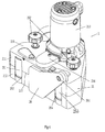
- the working surface 11 of the table saw 1 is installed with a planer 2, and the planer 2 consists of a housing 21 and a blade shaft 23 (see FIG. 6 ).
- the position of the planer 2 corresponding to the work table 10 is fixed, and when the planer 2 is working, the blade shaft 23 will rotate and form a planing line with fixed position, which is parallel to axis Z; as well known in the industry, the blade of the blade shaft 23 is more protruding than other parts, so this planing line will be the most outer end of the blade away from the housing 21 of planer 2 during the rotation of the blade shaft 23.
- the workpiece When the planer 2 is working, the workpiece is pushed along the direction of axis X, so the planing line and axis X cross and form a working surface during the working of planer 2; the part of the workpiece which is beyond the working surface will be planed, and the part not beyond the working surface will be retained.
- the work table is installed with a first installation mechanism 19, which is represented as two screw holes 19 in this embodiment, and the line formed by these two screw holes 19 is along the direction of axis X; corresponding installation on the planer 2 is a second installation mechanism 29, which is represented as two holes 291 and two studs 292 which should traverse the said holes 291 on the housing 21 and be installed in the said screw holes 19.
- the planer 2 can be detachably arranged on the work table 10.
- the first installation mechanism 19 and the second installation mechanism 29 have multiple optional embodiments, for example, the first installation mechanism 19 can be a slot and the second installation mechanism 29 can be a corresponding convex, and we won't elaborate here.
- the work table 10 is provided with a long slot 191 and a short slot 192, which are interconnected; the long slot 191 is a hole that goes through the working chamber 15, and the short slot 192 is a concave installed on the work table 10, the shape of which shall match that of the convex 214 below the housing 21 of the planer 2 (see FIG. 5 ).
- the shapes of a long board 193 and a short board 194 shall match the shapes of the long slot 191 and the short slot 192 respectively, which shall be installed above the long slot 191 and the short slot 192.
- the long board 193 When the cutting device 3 is working, the long board 193 is moved away to expose the long slot 191, and the short board 194 covers the short slot 192; when the planer 2 is working, the long board 193 covers the long slot 191, and the short board 194 is moved away to expose the short slot 192.
- the cutting device 3 includes a first motor (not shown in the figure) and a blade 33 which conducts the cutting movement with the first motor; it is represented as a circular saw blade 33, which is almost parallel to axis X and can move up and down along axis Z; when it moves upward, it can go through the long slot 191 part and be above the working surface 11, and when it moves downward, it can be under the working surface 11.
- the embodiment of its moving upward and downward is well known to technicians in this field, and we will not elaborate here.
- the circular saw blade 33 rotary cuts the workpiece, and due to the thickness of the circular saw blade 33, two cutting planes will be formed from the cutting from the circular saw blade 33, and the one close to the front end of the work table 10 is called the front cutting plane, and that close to the back end of the work table 10 is called the back cutting plane. Both the front cutting plane and the back cutting plane are parallel to the plane formed by axis X and axis Z, and perpendicular to the work table 10.
- the part outside of the range between the front cutting plane and the back cutting plane will be cut off, and in accordance with the actual working situation, of the front cutting plane and the back cutting plane, the one that is closer the fence 4, i.e., one cutting plane of the initial position of the workpiece is the working surface of the circular saw blade 33, and the part of the workpiece which is beyond this working surface will be cut off, and the part which does not exceed the working surface will be retained.
- the location and installation location of blade shaft 23 of planer 2 have been preset, so that the planing line will be generally in the front cutting plane. Due to manufacturing and assembly errors, in reality, it is impossible that the planing line can be precisely located on the front cutting plane; however, this error is within the range of tolerable errors required by the machining, i.e., the planing line will be generally in the front cutting plane. In this way, the planer 2 will be installed on the working surface 11 and begin to work; if the position of the fence 4 is fixed, the minimum distance between the blade shaft 23 and the fence 4 is the distance between the planing line and the fence 4, which is equal to the distance between the part of the circular saw blade 33 which works above the working surface and the fence 4.
- the working surface of the circular saw blade 33 and the blade shaft 23 will be on the same plane.
- the planing work can be conducted.
- the displacement amount of the fence is the planing amount.
- first installation mechanism 19 there is only one set of first installation mechanism 19 at the back of the circular saw blade 33, and when the planer 2 is planing the workpiece, it makes the fence 4 located at the front of the work table 10 compared to the blade shaft 23, and the distance between the circular saw blade 33 and the fence 4 is the distance between the front cutting plane and the fence 4; however, optionally, the first installation mechanism 19 can also be located at the front of the circular saw blade 33, which makes the fence 4 located at the back of the work table 10 compared with the blade shaft 23 when the planer 2 is planing the workpiece, and at this time, the planing line of the blade shaft 23 must be located on the back cutting plane of the circular saw blade 33; in this way, when planer 4 and the circular saw blade 33 are working respectively, if the location of the fence 4 is fixed, the minimum distance between the blade shaft 23 and the fence 4 is still equal to the distance between the circular saw blade 33 and the fence 4; the work table 10 can have two sets of first installation mechanism 19 with two locations mentioned above at the same time, but its setting
- the table saw 1 can have an optimized work procedure consisting of a rough machining phase and a fine machining phase; during the rough machining phase, the operator has to firstly make sure that the long board 193 is off the long slot 193 and the short board 194 covers the short slot 192, and move the circular saw blade 33 to an appropriate location on the working surface 11; then, adjust the fence 4 to an appropriate location by referring to the scale, and lean one side of the workpiece on the fence 4, and slide toward the circular saw blade 33 along the fence 4 to make the circular saw blade 33 rotary cut the workpiece.
- the cutting device 3 and the planer 2 can work independently, but they cannot work at the same time.
- planer 2 in the present invention will be given in the following.
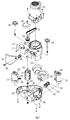
- the housing 21 of the planer 2 includes the motor housing 213, upper housing 211 and lower housing 212 from up to down, and they are connected successively by the screw-hole device.
- the bottom of the lower housing 212 is installed with a convex 214 which bulges downward; when the planer 2 is installed on the work table 10, the convex 214 is installed on the short slot 192 of the work table 10, and the blade shaft 23 is installed between the top of the upper housing 211 and the convex 214 at the bottom of the lower housing 212; when the planer 2 is installed on the work table 10, the bottom of the blade shaft 23 is slightly lower than the working surface of the work table 10, so in this way, the blade shaft 23 can plane thoroughly to the bottom of the workpiece, and incomplete planing of workpiece bottom caused by the slit between the blade shaft 23 and the work table 10 can be avoided.
- the housing 21 has an upper surface 215 formed by the top of the upper housing 211 and a planing surface 217 which is suitable to face and connect the workpiece.
- the motor housing 213 is above the upper surface 215, where a second motor is located (not shown in the figure).
- the upper surface 215 is also installed with belt wheel housing 216 and two holes 291 mentioned above, and the said holes 291 can hold the said two studs 292.
- the hole 291 can be set as a longitudinal hole, so that after installation, the planer 2 can have a small movement along the direction of axis Y to adjust the circular saw blade 33 and make the planing line of the blade shaft 23 to be exactly on the cutting plane of the circular saw blade 33.
- an adjustment device 293 is set between the planer 2 and the work table 10 (see FIG. 6 ).
- the adjust device 293 includes a base 294 fixedly connect to the work table 10 and a adjustment screw 295 fixedly connect to the planer 2; the adjustment screw 295 is installed on the base 294 by screws, and the adjustment screw 295's movement along the axis direction can be conducted through rotary adjustment which can also cause a slight movement of the planer 2 along the direction of axis Y, and in this way to adjust the blade shaft 23.
- This adjust device 293 is well known to technicians in this field, and we won't make further elaboration here.
- the planing surface 217 is arranged with three slots in an interval along the direction of axis Z, and they are successively the first roller slot 252 used to install the first roller 251, the blade shaft slot 231 to install the blade shaft 23 and the second roller slot 254 used to install the second roller 253.
- the said blade shaft 23 partly protrudes above the said planning surface 217 at the radial direction.
- the said first roller 251 and second roller 253 are cylinders of the same size and shape movably installed in the housing 21 at the radial direction, the diameter of which is larger than the width of the first roller slot 252 and the second roller slot 254.
- the first roller 251 and the second roller 253 can pivot around their longitudinal axes.
- the length they protrude above the planing surface 217 on the direction of axis Y is no shorter than the length protruded by the blade shaft 23 on the direction of axis Y outside the planing surface 217; when oppressed, the first roller 251 and second roller 253 can completely retract to be within the planing surface 217.
- the workpiece oppressed the first roller 251 and second roller 253 back to the planing surface 217, and the first roller 251 and second roller 253 also impose a opposing force to the workpiece and make it tightly stick to the fence 4 to improve accuracy and stability of the planing process.
- both the first roller 251 and second roller 253 have adopted rubber materials with a relatively big frictional force, so that during the planing process, the workpiece can lead the first roller 251 and second roller 253 to pivot around their longitudinal axes, enabling a more smooth and stable feeding process.
- the planing surface 217 is also installed with a guard 26, and the said guard 26 installed on the side of the planing surface 217 by a pin 261, and it can turn around between an opening position and a closing position through this pin 261; in the said closing position, the said guard 26 covers the said blade shaft slot 231, and in the said opening position, the said guard 26 uncovers the said blade shaft slot 231.
- both of the said first roller 251 and second roller 253 protrude outside of the planing surface 217, and the guard 26 will be in the closing position for safety protection; only when the workpiece is pushed tightly along the planing surface 217 from the side of the guard 26 to the other side is the guard 26 pushed to the opening position, and the first roller 251 and second roller 253 will be pressed back to be within the planing surface 217, and the blade shaft 23 planes the workpiece.
- the workpiece itself forms a cover to the blade shaft 23; after the planing, the first roller 251, the second roller 253 and the guard 26 will return to their original positions, so in this way, the operator will always be in a safe state during the whole process from preparation to completion of planing.
- the second motor in the motor housing 213 has a motor output shaft (not shown in the figure), which is enclosed with a belt 22, and the belt 22 is also coupled with a belt wheel 232; the said belt wheel 232 is located on the upper surface 215 of the planer 2, and installed at the upper blade shaft 233 of the blade shaft 23 which has passed through the upper housing 211, and the said blade shaft 23 also has a lower blade shaft 234 installed at the bottom of the lower housing 212.
- rotary output of the second motor is transferred to the blade shaft 23 through the belt 22 and the belt wheel 232, which makes the blade shaft 23 to conduct rotary planing.
- the said upper surface 215 is also installed with a belt wheel housing 216 which covers the said belt 22 and belt wheel 232.
- the said first roller 251 and second roller 253 are installed between the upper housing 211 and the lower housing 212 on the two sides of the blade shaft 23, and they have the same structure and installation method; in the following, description will be given by using the first roller 251 as the example: the first roller 251 is pivotably installed in the first roller stand 241, and the first roller stand 241 has the first principal shaft 242 pivotably installed between the upper housing 211 and the lower housing 212; the first convex wall 244 is installed in the lower housing 212, and the first spring 243 is installed between the first convex wall 244 and the first principal shaft 242, which can push the first principal shaft 242 pivot to further push the said first roller 251 protruding outside of the planing surface 217.
- the planer 2 also has the second roller stand 281, the second principal shaft 282, the second convex wall 284 and the second spring correspondingly installed to the blade shaft 23 (not shown in the figure).
- the said guard 26 is installed on the part of the upper housing 211 which is on the side of the planing surface 217 via the pin 261, and a torsional spring 262 is installed between the guard 217 and the upper housing 211; the said torsional spring 262 oppresses the guard 26 in its closing position.
- a dust collection device 219 is also installed between the upper housing 211 and the lower housing 212, the specific structure of which is not related to the present invention, so we won't make further elaboration here.
- the planer 2 is installed far behind the long slot 191, so the cutting line of the planer 2 and the cutting plane of the circular saw blade 33 won't be in the same plane anymore.
- the frame 131 is installed with a scale rule 5 which can slide along axis Y and be fixed at the preset position.
- the scale rule 5 can slide in the slot of the frame (not shown in the figure), and its fixation method is the screw compact structure well known in the industry, so we won't elaborate here.
- the scale rule 5 shall have at least one 0 scale mark as the benchmark scale to measure the workpiece specifications. When the planer 2 is working, the operator can move the scale rule 5 to align its benchmark of 0 scale mark with the cutting line of the planer 2, i.e., the most outside to the fence 4 when the blade shaft 23 is working.
- the planer 2 is off the work table 10.
- the benchmark of 0 scale mark of the scale rule 5 is aligned with the cutting plane of the cutting device, i.e., the most outside of the circular saw blade 33 to the fence 4.
- This embodiment has a preferred work procedure, i.e.: firstly, put the cutting device 3 on its working state, and the operator adjusts the location of the scale rule 5 to align its benchmark of 0 scale mark with the cutting plane of the circular saw blade 33, then adjust the fence 4 to an appropriate position in accordance with the cutting requirement of the workpiece, and cut the workpiece, and this position will have an marked scale on the scale rule 5; then, put the planer 2 on its working state, adjust the scale rule 5 to align its benchmark of 0 scale mark with the planing line of the planer 2, and then adjust the fence 4 to an appropriate position in accordance with the marked scale, and plane the workpiece.
- planing line and cutting plane of this embodiment are not in the same plane, during workpiece cutting and planing by the table saw 1, by setting up scale rule 5 with adjustable positions, the benchmark of 0 scale mark of the scale rule 5 can be aligned with the cutting plane and planing line, so that they will have the same benchmark scale, and the marked scale of cutting can be referred to during the planing.
Landscapes
- Life Sciences & Earth Sciences (AREA)
- Engineering & Computer Science (AREA)
- Mechanical Engineering (AREA)
- Wood Science & Technology (AREA)
- Forests & Forestry (AREA)
- Milling, Drilling, And Turning Of Wood (AREA)
Applications Claiming Priority (2)
| Application Number | Priority Date | Filing Date | Title |
|---|---|---|---|
| CN2008101945205A CN101758563B (zh) | 2008-10-30 | 2008-10-30 | 台锯 |
| PCT/CN2009/074681 WO2010048890A1 (fr) | 2008-10-30 | 2009-10-29 | Scie à table |
Publications (2)
| Publication Number | Publication Date |
|---|---|
| EP2347876A1 true EP2347876A1 (fr) | 2011-07-27 |
| EP2347876A4 EP2347876A4 (fr) | 2013-11-06 |
Family
ID=42128269
Family Applications (1)
| Application Number | Title | Priority Date | Filing Date |
|---|---|---|---|
| EP09823082.4A Withdrawn EP2347876A4 (fr) | 2008-10-30 | 2009-10-29 | Scie à table |
Country Status (4)
| Country | Link |
|---|---|
| US (1) | US8746668B2 (fr) |
| EP (1) | EP2347876A4 (fr) |
| CN (1) | CN101758563B (fr) |
| WO (1) | WO2010048890A1 (fr) |
Families Citing this family (13)
| Publication number | Priority date | Publication date | Assignee | Title |
|---|---|---|---|---|
| US8181680B1 (en) * | 2009-04-03 | 2012-05-22 | Allen Ip Inc. | Machinery fence support facilitating fence movement in a direction perpendicular to a length of the fence |
| CN102166766B (zh) * | 2011-02-11 | 2016-09-14 | 苏国成 | 手提电刨加工型材端部的装置 |
| CN103895069B (zh) * | 2012-12-26 | 2017-04-05 | 苏州宝时得电动工具有限公司 | 台式刨锯一体机 |
| CN203443542U (zh) * | 2013-07-19 | 2014-02-19 | 鸿富锦精密工业(深圳)有限公司 | 量测机 |
| CN103909582B (zh) * | 2014-03-26 | 2015-10-28 | 苏州铁逸机械科技有限公司 | 一种自动化锯床的切割机构 |
| CN104118020B (zh) * | 2014-07-22 | 2017-01-18 | 福建工程学院 | 一种两用刨 |
| WO2017177226A1 (fr) * | 2016-04-08 | 2017-10-12 | Robert Bosch Tool Corporation | Limiteur de taille de lame |
| CN108058234A (zh) * | 2018-01-10 | 2018-05-22 | 安吉鑫茂家居有限公司 | 一种家具生产用小型便捷锯切装置 |
| CN108838452B (zh) * | 2018-09-14 | 2024-06-21 | 上海特波电机有限公司 | 刨加工电机底脚工装 |
| CN109333657A (zh) * | 2018-11-15 | 2019-02-15 | 江苏金飞达电动工具有限公司 | 自防护的台锯 |
| CN112453560B (zh) * | 2020-12-04 | 2024-07-30 | 中冶赛迪技术研究中心有限公司 | 一种成排锯切钢管跟踪标记装置及方法 |
| CN114102783A (zh) * | 2021-10-23 | 2022-03-01 | 徐州麦卡锡木业有限公司 | 一种实木门板生产加工设备及其使用方法 |
| US11465312B1 (en) * | 2022-04-08 | 2022-10-11 | Henry Wang | Coded push block |
Family Cites Families (44)
| Publication number | Priority date | Publication date | Assignee | Title |
|---|---|---|---|---|
| US1802096A (en) * | 1929-04-15 | 1931-04-21 | Delta Mfg Co | Planer attachment for jointers |
| US2085603A (en) * | 1934-10-26 | 1937-06-29 | Black & Decker Mfg Co | Manually portable power-driven rotary planer |
| US2595483A (en) * | 1950-12-29 | 1952-05-06 | Buss Machine Works | Vacuum center table for planers |
| US2780254A (en) * | 1955-05-05 | 1957-02-05 | Williams & Hussey Machine Corp | Hold-down rollers for planers and the like |
| US2771104A (en) * | 1955-06-03 | 1956-11-20 | Raymond J Saxe | Planer attachment for electric drills or the like |
| US2783796A (en) * | 1955-07-21 | 1957-03-05 | Patterson Robert Glenn | Edge planers |
| US2888965A (en) * | 1958-01-14 | 1959-06-02 | Carleton A Phillips | Mountings for a portable electric motor |
| DE1293100B (de) * | 1965-01-27 | 1969-04-17 | Susemihl Rolf | Mehrzweckarbeitsgeraet |
| US3342226A (en) * | 1966-04-29 | 1967-09-19 | Henry J Marcoux | Collapsible work table |
| US3734151A (en) * | 1970-09-21 | 1973-05-22 | H Skripsky | Portable workbench |
| US4105055A (en) * | 1976-09-01 | 1978-08-08 | Robert Brenta | Portable workshop |
| GB1602974A (en) * | 1977-07-07 | 1981-11-18 | Bondgrade Ltd | Work bench |
| CA1078709A (fr) * | 1978-05-24 | 1980-06-03 | Mustafa Fehric | Etabli polyvalent de menuiserie |
| US4265283A (en) * | 1979-01-02 | 1981-05-05 | The Triangle Corporation | Work bench structure |
| US4335765A (en) * | 1979-11-23 | 1982-06-22 | Murphy Rholand D | Portable multi-purpose construction table |
| US4427042A (en) * | 1981-05-13 | 1984-01-24 | Emerson Electric Co. | Power tool |
| NO149619C (no) * | 1982-02-16 | 1984-05-23 | Oeyvind Haeger | Anordning ved maskin til trebearbeiding |
| US4483573A (en) * | 1982-07-09 | 1984-11-20 | Keller David L | Tool adapter for working table top storage cabinet |
| US4445412A (en) * | 1982-07-16 | 1984-05-01 | Peters Jerry M | Improved table saw arrangement |
| US4516612A (en) * | 1982-09-03 | 1985-05-14 | Wiley Edward R | Multipurpose table saw |
| US5024257A (en) * | 1990-04-18 | 1991-06-18 | Lloyd James E | Woodworking machine |
| US5063983A (en) * | 1990-06-11 | 1991-11-12 | David Barry | Router table with swing arm measuring scale, block and method |
| CN2096459U (zh) | 1991-06-12 | 1992-02-19 | 高凤春 | 多用途组合木工电刨 |
| US5431206A (en) * | 1993-10-25 | 1995-07-11 | Mcallister; Michael J. | Portable workstation |
| US6080041A (en) * | 1996-05-23 | 2000-06-27 | Greenland; Darrell | Compact motorized table saw |
| CA2193794A1 (fr) | 1996-12-23 | 1998-06-23 | Newnes Machine Ltd. | Cadre de scie circulaire a trait de scie mince |
| CN2314911Y (zh) | 1997-12-10 | 1999-04-21 | 赵华 | 自动送料压刨床和多功能平刨床组合木工机床 |
| DE19853374B4 (de) | 1998-11-19 | 2007-06-21 | Robert Bosch Gmbh | Handhobelmaschine |
| US20060219076A1 (en) | 2005-03-31 | 2006-10-05 | Gass Stephen F | Table saw throat plates and table saws including the same |
| GB2359040A (en) * | 2000-02-09 | 2001-08-15 | Geoffrey Manning | A transportable workbench |
| CN2460274Y (zh) | 2000-12-28 | 2001-11-21 | 李成民 | 方材一次成型角木木线机 |
| US6601621B2 (en) * | 2001-04-18 | 2003-08-05 | Black & Decker Inc. | Portable Power Planer |
| US6857456B2 (en) * | 2001-08-14 | 2005-02-22 | Geoffrey Manning | Workbench |
| US20030097921A1 (en) * | 2001-11-26 | 2003-05-29 | Techtronic Industries Col, Ltd. | Motorized wood working tool having a low friction table |
| CN2597174Y (zh) | 2003-01-29 | 2004-01-07 | 莫阿新 | 木工精工多片圆锯床 |
| US20060101958A1 (en) * | 2003-07-31 | 2006-05-18 | Garcia Jaime E | Table saw |
| FR2861634A1 (fr) * | 2003-10-31 | 2005-05-06 | Lurem Machines A Bois | Machine a bois |
| US7028683B1 (en) * | 2004-06-14 | 2006-04-18 | Yuehting Chen | Structural improvement in a portable stone cutter |
| EP1784290B1 (fr) | 2004-08-31 | 2012-06-27 | Robert Bosch Gmbh | Guide parallele pour scie a table |
| CA2531910A1 (fr) * | 2004-12-30 | 2006-06-30 | Bench Dog, Inc. | Table a toupie |
| CN2808491Y (zh) * | 2005-06-20 | 2006-08-23 | 王建康 | 多用木工组合机床 |
| CN2815570Y (zh) * | 2005-08-26 | 2006-09-13 | 苏州宝时得电动工具有限公司 | 台锯 |
| DE602006019649D1 (de) * | 2006-11-13 | 2011-02-24 | Dario Marco | Sägemaschine, wie bandsäge oder dergleichen, für steine, marmor, holz oder anderes material mit in verschiedenen positionen davon einstellbarer schnittebene |
| CN201279839Y (zh) * | 2008-10-31 | 2009-07-29 | 苏州宝时得电动工具有限公司 | 台锯 |
-
2008
- 2008-10-30 CN CN2008101945205A patent/CN101758563B/zh not_active Expired - Fee Related
-
2009
- 2009-10-29 US US13/126,453 patent/US8746668B2/en not_active Expired - Fee Related
- 2009-10-29 EP EP09823082.4A patent/EP2347876A4/fr not_active Withdrawn
- 2009-10-29 WO PCT/CN2009/074681 patent/WO2010048890A1/fr not_active Ceased
Also Published As
| Publication number | Publication date |
|---|---|
| CN101758563B (zh) | 2012-05-30 |
| US20110259315A1 (en) | 2011-10-27 |
| WO2010048890A1 (fr) | 2010-05-06 |
| EP2347876A4 (fr) | 2013-11-06 |
| CN101758563A (zh) | 2010-06-30 |
| US8746668B2 (en) | 2014-06-10 |
Similar Documents
| Publication | Publication Date | Title |
|---|---|---|
| US8746668B2 (en) | Table saw | |
| US3935777A (en) | Portable cutting device | |
| US5165317A (en) | Multi-use apparatus for the control of portable power tools | |
| US5653273A (en) | Universal precision woodworking center | |
| US4078309A (en) | Miter saw | |
| CN101733471B (zh) | 切割机 | |
| US20140026725A1 (en) | Universal edge guide | |
| CA2533848C (fr) | Outil de coupe de panneau mural | |
| US11027453B2 (en) | Cutting tool | |
| WO2008022116A2 (fr) | Système pour former un joint à onglet | |
| US4378716A (en) | Ripper attachment for multi-purpose woodworking power tool guide table | |
| US4987813A (en) | Apparatus for installation of a power saw and fence in a table | |
| AU2014261255B2 (en) | Power tool | |
| CN201279839Y (zh) | 台锯 | |
| US8776656B2 (en) | Circular and miter box saw | |
| US20160067802A1 (en) | Miter Gauge Lock For Sliding Table Saws | |
| CN107876876B (zh) | 切割附件及切割工具 | |
| US20080127790A1 (en) | Power saw miter guide | |
| US3171454A (en) | Means for adjusting positions of jointer cutters | |
| US20060011033A1 (en) | Mitre saw with adjustable fence | |
| US8746116B2 (en) | Method and apparatus for making wide cuts | |
| EP1362658B1 (fr) | Machine pour scier des panneaux | |
| CN213732203U (zh) | 一种激光定位便携开孔装置 | |
| WO2011085681A1 (fr) | Table de travail | |
| CA2749924A1 (fr) | Outil de mesure, de serrage et de guide de coupe |
Legal Events
| Date | Code | Title | Description |
|---|---|---|---|
| PUAI | Public reference made under article 153(3) epc to a published international application that has entered the european phase |
Free format text: ORIGINAL CODE: 0009012 |
|
| 17P | Request for examination filed |
Effective date: 20110421 |
|
| AK | Designated contracting states |
Kind code of ref document: A1 Designated state(s): AT BE BG CH CY CZ DE DK EE ES FI FR GB GR HR HU IE IS IT LI LT LU LV MC MK MT NL NO PL PT RO SE SI SK SM TR |
|
| AX | Request for extension of the european patent |
Extension state: AL BA RS |
|
| RAP1 | Party data changed (applicant data changed or rights of an application transferred) |
Owner name: POSITEC POWER TOOLS (SUZHOU) CO., LTD |
|
| DAX | Request for extension of the european patent (deleted) | ||
| A4 | Supplementary search report drawn up and despatched |
Effective date: 20131007 |
|
| RIC1 | Information provided on ipc code assigned before grant |
Ipc: B23D 45/06 20060101ALI20130930BHEP Ipc: B28D 1/04 20060101AFI20130930BHEP |
|
| 17Q | First examination report despatched |
Effective date: 20140814 |
|
| STAA | Information on the status of an ep patent application or granted ep patent |
Free format text: STATUS: THE APPLICATION IS DEEMED TO BE WITHDRAWN |
|
| 18D | Application deemed to be withdrawn |
Effective date: 20150106 |