EP2348150B1 - Wäschebehandlungsmaschine - Google Patents
Wäschebehandlungsmaschine Download PDFInfo
- Publication number
- EP2348150B1 EP2348150B1 EP11159007A EP11159007A EP2348150B1 EP 2348150 B1 EP2348150 B1 EP 2348150B1 EP 11159007 A EP11159007 A EP 11159007A EP 11159007 A EP11159007 A EP 11159007A EP 2348150 B1 EP2348150 B1 EP 2348150B1
- Authority
- EP
- European Patent Office
- Prior art keywords
- tubular
- vaporizer
- steam
- heating means
- tubular vaporizer
- Prior art date
- Legal status (The legal status is an assumption and is not a legal conclusion. Google has not performed a legal analysis and makes no representation as to the accuracy of the status listed.)
- Not-in-force
Links
Images

Classifications
-
- D—TEXTILES; PAPER
- D06—TREATMENT OF TEXTILES OR THE LIKE; LAUNDERING; FLEXIBLE MATERIALS NOT OTHERWISE PROVIDED FOR
- D06F—LAUNDERING, DRYING, IRONING, PRESSING OR FOLDING TEXTILE ARTICLES
- D06F39/00—Details of washing machines not specific to a single type of machines covered by groups D06F9/00 - D06F27/00
- D06F39/40—Steam generating arrangements
-
- D—TEXTILES; PAPER
- D06—TREATMENT OF TEXTILES OR THE LIKE; LAUNDERING; FLEXIBLE MATERIALS NOT OTHERWISE PROVIDED FOR
- D06F—LAUNDERING, DRYING, IRONING, PRESSING OR FOLDING TEXTILE ARTICLES
- D06F58/00—Domestic laundry dryers
- D06F58/20—General details of domestic laundry dryers
- D06F58/203—Laundry conditioning arrangements
-
- D—TEXTILES; PAPER
- D06—TREATMENT OF TEXTILES OR THE LIKE; LAUNDERING; FLEXIBLE MATERIALS NOT OTHERWISE PROVIDED FOR
- D06F—LAUNDERING, DRYING, IRONING, PRESSING OR FOLDING TEXTILE ARTICLES
- D06F58/00—Domestic laundry dryers
- D06F58/32—Control of operations performed in domestic laundry dryers
- D06F58/34—Control of operations performed in domestic laundry dryers characterised by the purpose or target of the control
- D06F58/36—Control of operational steps, e.g. for optimisation or improvement of operational steps depending on the condition of the laundry
- D06F58/44—Control of operational steps, e.g. for optimisation or improvement of operational steps depending on the condition of the laundry of conditioning or finishing, e.g. for smoothing or removing creases
-
- D—TEXTILES; PAPER
- D06—TREATMENT OF TEXTILES OR THE LIKE; LAUNDERING; FLEXIBLE MATERIALS NOT OTHERWISE PROVIDED FOR
- D06F—LAUNDERING, DRYING, IRONING, PRESSING OR FOLDING TEXTILE ARTICLES
- D06F2103/00—Parameters monitored or detected for the control of domestic laundry washing machines, washer-dryers or laundry dryers
- D06F2103/52—Parameters monitored or detected for the control of domestic laundry washing machines, washer-dryers or laundry dryers related to electric heating means, e.g. temperature or voltage
-
- D—TEXTILES; PAPER
- D06—TREATMENT OF TEXTILES OR THE LIKE; LAUNDERING; FLEXIBLE MATERIALS NOT OTHERWISE PROVIDED FOR
- D06F—LAUNDERING, DRYING, IRONING, PRESSING OR FOLDING TEXTILE ARTICLES
- D06F2103/00—Parameters monitored or detected for the control of domestic laundry washing machines, washer-dryers or laundry dryers
- D06F2103/60—Parameters monitored or detected for the control of domestic laundry washing machines, washer-dryers or laundry dryers related to auxiliary conditioning or finishing agents, e.g. filling level of perfume tanks
- D06F2103/62—Parameters monitored or detected for the control of domestic laundry washing machines, washer-dryers or laundry dryers related to auxiliary conditioning or finishing agents, e.g. filling level of perfume tanks related to systems for water or steam used for conditioning or finishing
-
- D—TEXTILES; PAPER
- D06—TREATMENT OF TEXTILES OR THE LIKE; LAUNDERING; FLEXIBLE MATERIALS NOT OTHERWISE PROVIDED FOR
- D06F—LAUNDERING, DRYING, IRONING, PRESSING OR FOLDING TEXTILE ARTICLES
- D06F2105/00—Systems or parameters controlled or affected by the control systems of washing machines, washer-dryers or laundry dryers
- D06F2105/02—Water supply
-
- D—TEXTILES; PAPER
- D06—TREATMENT OF TEXTILES OR THE LIKE; LAUNDERING; FLEXIBLE MATERIALS NOT OTHERWISE PROVIDED FOR
- D06F—LAUNDERING, DRYING, IRONING, PRESSING OR FOLDING TEXTILE ARTICLES
- D06F2105/00—Systems or parameters controlled or affected by the control systems of washing machines, washer-dryers or laundry dryers
- D06F2105/28—Electric heating
-
- D—TEXTILES; PAPER
- D06—TREATMENT OF TEXTILES OR THE LIKE; LAUNDERING; FLEXIBLE MATERIALS NOT OTHERWISE PROVIDED FOR
- D06F—LAUNDERING, DRYING, IRONING, PRESSING OR FOLDING TEXTILE ARTICLES
- D06F58/00—Domestic laundry dryers
- D06F58/10—Drying cabinets or drying chambers having heating or ventilating means
Definitions
- the present invention relates to a home laundry machine.
- the present invention relates to a machine for drying and and/or washing laundry, to which the following description refers purely by way of example.
- laundry machines i.e. rotary-drum laundry driers substantially comprise a substantially parallelepiped-shaped outer box casing; a cylindrical laundry drum housed in axially rotating manner inside the box casing, directly facing a laundry loading and unloading opening formed in the front face of the casing; a door hinged to the front face of the casing to rotate to and from a rest position closing the opening in the front face of the casing to seal the laundry drum; and an electric motor for rotating the laundry drum about its longitudinal axis inside the casing.
- Rotary-drum laundry driers of the above type also comprise a closed-circuit, hot-air generator designed to circulate inside the laundry drum a stream of hot air with a low moisture content and which flows through the laundry drum and over the laundry inside the drum to rapidly dry the laundry.
- the closed-circuit, hot-air generator comprises an air/air heat exchanger and an electric heater located one after the other along an air recirculating conduit, the two ends of which are connected to opposite ends of the laundry drum.
- the air/air heat exchanger provides for rapidly cooling the airflow from the laundry drum to condense the surplus moisture in the airflow; and the heater provides for rapidly heating the airflow from the heat exchanger back to the laundry drum, so that the air flowing into the drum is heated rapidly to a temperature higher than or equal to that of the same air flowing out of the laundry drum.
- Some more recently marketed rotary-drum driers also feature a pressurized-steam generator which, at the end of the drying cycle, feeds a jet of steam into the laundry drum to eliminate or at least greatly reduce creasing of the fabrics during the drying cycle.
- the pressurized-steam generator substantially comprises a tubular vaporizer for receiving a predetermined amount of water; a heating element coupled to the tubular vaporizer to boil and convert into steam the water in the tubular vaporizer; and a steam exhaust pipe connecting, inside the casing, the outlet of the tubular vaporizer to a nozzle located at the laundry loading-unloading opening for injecting into the laundry drum the steam produced by the tubular vaporizer.
- the water emitted by the nozzle is produced by condensation of the steam flowing along the portion of the exhaust pipe between the tubular vaporizer and the steam nozzle. That is, as it flows along the exhaust pipe, part of the steam from the tubular vaporizer is cooled by the exhaust pipe and converted into droplets, which are injected by the nozzle into the drum, thus damping the laundry.
- WO 2006/019361 A1 discloses a washing machine comprising a cylindrical vaporizer for evaporating a given amount of water.
- a steam exhaust pipe of a steam generator has a tubular portion which is wound about the cylindrical vaporizer.
- the vaporizer is heated by gas burners acting on a base area of the cylindrical vaporizer.
- the tubular portion of the exhaust pipe is heated by way of thermal conduction through the lateral area of the cylindrical vaporizer.
- a home laundry machine as claimed in Claim 1 and preferably, though not necessarily, in any one of the Claims depending directly or indirectly on Claim 1.
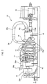
- Number 1 in Figure 1 indicates as a whole a home laundry machine for drying and/or washing laundry, substantially comprising a preferably, though not necessarily, parallelepiped-shaped outer box casing 2; an airtight, preferably, though not necessarily, cylindrical laundry drying tub or chamber 3 for housing the laundry to be dried, and which is fixed substantially horizontally inside casing 2, directly facing a laundry loading and unloading opening 2a formed in the front face of casing 2; a door 4 hinged to the front face of casing 2 to rotate to and from a rest position closing opening 2a in the front face to seal laundry drying tub 3; and a preferably, though not necessarily, cylindrical laundry drum 5 for housing the laundry to be dried, and which is housed in axially rotating manner and preferably, though not necessarily, horizontally inside drying tub 3.
- laundry drum 5 has an end wall 5a, and possibly a cylindrical lateral wall perforated, or at any rate permeable to air, to permit airflow into drum 5, and is mounted for rotation about its longitudinal axis L which, in the example shown, coincides with the longitudinal axis of drying tub 3.
- Laundry machine 1 also comprises an electric motor 6 or similar, which, on command, rotates laundry drum 5 about longitudinal axis L inside drying tub 3; and a closed-circuit, hot-air generator 7 housed inside casing 2 and designed to circulate through laundry drum 5 a stream of hot air having a low moisture level, and which flows over and rapidly dries the laundry inside drum 5.
- hot-air generator 7 provides for gradually drawing air from drying tub 3; extracting surplus moisture from the hot air drawn from drying tub 3; heating the dehumidified air to a predetermined temperature, normally higher than the temperature of the air from drying tub 3; and feeding the heated, dehumidified air back into drying tub 3, where it flows over, to rapidly dry, the laundry inside the tub.
- hot-air generator 7 provides for continually dehumidifying and heating the air circulating inside drum 5 to rapidly dry the laundry inside the drum, and substantially comprises:
- the intake end of recirculating conduit 8 is integrated in door 4, and the exhaust end of recirculating conduit 8 is connected directly to drying tub 3, in front of end wall 5a of laundry drum 5.
- machine 1 also comprises an electronic control unit 12, which controls electric motor 6, fan 9, heat exchanger 10 and heater 11 in predetermined manner, as memorized inside it, to perform the user-selected drying cycle.
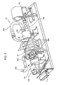
- laundry machine 1 also has a steam generator 15, which comprises a tubular vaporizer 16, which evaporates instantaneously water, without permanently storing any amount of water on the inside; a pump 18 which, on command, pumps a given amount of water into tubular vaporizer 16 from a vessel 13; a heater 19 fitted to tubular vaporizer 16 to boil and convert the water inside tubular vaporizer 16 into steam; and a steam exhaust pipe 20 for feeding the steam produced in tubular vaporizer 16 into drying tub 3.
- a steam generator 15 comprises a tubular vaporizer 16, which evaporates instantaneously water, without permanently storing any amount of water on the inside; a pump 18 which, on command, pumps a given amount of water into tubular vaporizer 16 from a vessel 13; a heater 19 fitted to tubular vaporizer 16 to boil and convert the water inside tubular vaporizer 16 into steam; and a steam exhaust pipe 20 for feeding the steam produced in tubular vaporizer 16 into drying tub 3.
- tubular vaporizer 16 has an inlet 16a connected to and supplied by pump 18 with the water to be evaporated, and a steam outlet 16b.
- Exhaust pipe 20 is connected at one end to the outlet 16b of tubular vaporizer 16, and at the opposite end to a nozzle 17 located at the opening of drying tub 3 to inject steam into the tub.
- exhaust pipe 20 of steam generator 15 has at least one tubular portion 20a contacting heater 19, so that the steam flowing along tubular portion 20a is overheated to a certain extent by heater 19.
- heater 19 is positioned contacting the outer wall of tubular vaporizer 16, so as to heat tubular vaporizer 16 and instantaneously evaporate the whole water inside tubular vaporizer 16; and the tubular portion 20a of exhaust pipe 20 is wound about tubular vaporizer 16, so as to contact and be overheated by heater 19, and so overheat the steam flowing inside it.
- tubular vaporizer 16 comprises a closed, substantially tubular vessel, preferably, though not necessarily, made of metal; and tubular portion 20a of exhaust pipe 20 is wound about, and in contact with the outer wall of tubular vaporizer 16.
- Heater 19 is interposed between the outer wall of tubular vaporizer 16 and tubular portion 20a of exhaust pipe 20, so as to heat tubular vaporizer 16 and tubular portion 20a simultaneously.
- heater 19 comprises at least one electric resistor 19, or any other similar electric component capable of generating thermal heat, which is wound about tubular vaporizer 16 so as to contact both tubular portion 20a of exhaust pipe 20 and the outer wall of tubular vaporizer 16, and is connected to and powered by an electric power source (not shown).
- example tubular vaporizer 16 comprises a pipe made of metal, i.e. steel, having closed ends and extending along a longitudinal reference axis to a predetermined length.
- the metallic pipe defining the tubular vaporizer 16 could have a length approximately of about 145 mm and a diameter approximately of about 32 mm.
- Resistor 19 comprises a spiral body made of electric conductor metal, i.e. aluminium, which is firmly fixed on the external surface of tubular vaporizer 16 so as to be wound about tubular vaporizer 16.
- spiral body of the resistor 19 extends along the longitudinal reference axis of tubular vaporizer 16, and the tubular portion 20a of exhaust pipe 20 is wound about external surface of the tubular vaporizer 16, in such a way that its windings or turns are intercalate between turns of the spiral body of the resistor 19.
- tubular portion 20a corresponds to an intermediate portion of exhaust pipe 20, which is connected to outlet 16b of tubular vaporizer 16 by means of a tubular portion 20b preferably, though not necessarily, made of flexible material such as silicone, and is connected to the nozzle 17 by means of a tubular portion 20c preferably, though not necessarily, made of flexible material such as silicone.
- Steam generator 15 is controlled by electronic control unit 12, which drives pump 18 and, at the same time, regulates electric energy supply to heater 19, i.e. to resistor 19, to control the temperature inside tubular vaporizer 16 at the water evaporation stage.
- Steam generator 15 comprises a temperature sensor 21, which measures the temperature of the resistor 19 and outputs a temperature signal T to the electronic control unit 12; and a pressure sensor 22, which is associated to tubular vaporizer 16 ( Figure 2 e 3 ) to measure the inner pressure of tubular vaporizer 16. When the inner pressure measured into tubular vaporizer 16 exceeds a given pressure threshold value, pressure sensor 22 disconnects the electric power source to the resistor 19.
- pressure sensor 22 comprises an internal switching device 22a which connects the electric power source to the resistor 19.
- pressure sensor 22 detects an inner pressure into tubular vaporizer 16 exceeding a given pressure threshold value, such as about 1 bar, it switches off switching device 22a for interrupting the electrical supply to the resistor 19.
- the temperature sensor 21 in the Figure 1 and 2 example, it comprises a thermistor NTC (Negative Temperature Coefficient) coupled with the spiral body of resistor 19 to measure its temperature.
- NTC Negative Temperature Coefficient
- electronic control unit 12 controls the electric energy supplied by the electronic power source to resistor 19 on the basis of the temperature T measured by temperature sensor 21, heating both the outer wall of tubular vaporizer 16 and tubular portion 20a of exhaust pipe 20.
- electronic control unit 12 controls the heater 19 to have a temperature preferably ranging between approximately 130°C and 150°C, and is able to control pump 18 on the basis of the temperature T measured from temperature sensor 21, in such a manner as to change amount of water supplied to tubular vaporizer 16.
- electronic control unit 12 controls pump 18 and the temperature T of heater 19 to boil and instantaneously convert into steam the water in tubular vaporizer 16.
- Heater 19 heats tubular vaporizer 16 to evaporate the water, and simultaneously heats tubular portion 20a of exhaust pipe 20 to maintain a high temperature of the steam inside exhaust pipe 20. More specifically, steam generated inside tubular vaporizer 16 gets through the outlet 16b to the tubular portion 20a which overheats it.
- tubular portion 20a receives heat from heater 19, and releases it to, thus overheating, the steam flowing inside it. It should be pointed out that at this point tubular portion 20a receives the steam from tubular vaporizer 16 at a temperature of about 100°C, and outputs the steam to the tubular portion 20c at a temperature of about 140°C. The heated steam is then fed by exhaust pipe 20 to nozzle 17, which injects it into laundry drum 5.
Landscapes
- Engineering & Computer Science (AREA)
- Textile Engineering (AREA)
- Detail Structures Of Washing Machines And Dryers (AREA)
- Treatment Of Fiber Materials (AREA)
- Disintegrating Or Milling (AREA)
- Control Of Washing Machine And Dryer (AREA)
Claims (9)
- Wäschebehandlungsmaschine für den Haushalt (1), umfassend ein kastenförmiges Außengehäuse (2) und in dem Gehäuse einen Wäschebehälter (3, 5) zum Aufnehmen der zu trocknenden Wäsche sowie einen Dampfgenerator (15) zum Einführen einer gegebenen Menge an Dampf in den Wäschebehälter (3, 5), der seinerseits einen rohrförmigen Verdampfer (16) umfasst, um eine gegebene Menge an Wasser zu verdampfen; Heizmittel (19), um das Wasser zum Sieden zu bringen und es in dem rohrförmigen Verdampfer (16) in Dampf zu verwandeln; und eine Dampfausstoßleitung (20), um den im rohrförmigen Verdampfer (16) erzeugten Dampf in den Wäschebehälter (3, 5) einzuführen; wobei die Wäschebehandlungsmaschine für den Haushalt (1) dadurch gekennzeichnet ist, dass die Ausstoßleitung (20) des Dampfgenerators (15) mindestens einen rohrförmigen Teil (20a) aufweist, der sich in Kontakt mit den Heizmitteln (19) befindet, so dass der Dampf, der den rohrförmigen Teil (20a) entlangströmt, von den Heizmitteln (19) bis zu einem gewissen Ausmaß überhitzt wird und wobei der Dampfgenerator (15) umfasst: mindestens einen Temperatursensor (21), um die Temperatur (T) der Heizmittel (19) zu messen; und eine Pumpe (18), die eine gegebene Menge an Wasser in den rohrförmigen Verdampfer (16) pumpt; und elektronische Steuermittel (12), die die Pumpe (18) und/oder die Heizmittel (19) auf der Basis der Temperatur (T) steuern.
- Wäschebehandlungsmaschine für den Haushalt nach Anspruch 1, wobei die Heizmittel (19) derart angeordnet sind, dass sie sich in Kontakt mit der Außenwand des rohrförmigen Verdampfers (16) befinden, um den rohrförmigen Verdampfer (16) zu erhitzen; wobei der rohrförmige Teil (20a) der Ausstoßleitung (20) an dem rohrförmigen Verdampfer (16) derart angebracht ist, dass er sich in Kontakt mit diesem befindet, um so durch die Heizmittel (19) erhitzt zu werden.
- Wäschebehandlungsmaschine für den Haushalt nach Anspruch 2, wobei der rohrförmige Verdampfer (16) ein geschlossenes, im Wesentlichen rohrförmiges Gefäß umfasst; wobei der rohrförmige Teil (20a) der Ausstoßleitung (20) mindestens teilweise um den rohrförmigen Verdampfer (16) gewickelt ist und sich in Kontakt mit dessen Außenwand befindet.
- Wäschebehandlungsmaschine für den Haushalt nach Anspruch 3, wobei die Heizmittel (19) zwischen der Außenwand des rohrförmigen Verdampfers (16) und dem rohrförmigen Teil (20a) der Ausstoßleitung (20) angeordnet sind, um gleichzeitig den rohrförmigen Verdampfer (16) und den rohrförmigen Teil (20a) zu erhitzen.
- Wäschebehandlungsmaschine für den Haushalt nach Anspruch 4, wobei die Heizmittel (19) mindestens einen elektrischen Widerstand (19) umfassen.
- Wäschebehandlungsmaschine für den Haushalt nach Anspruch 5, wobei der mindestens eine elektrische Widerstand (19) um den rohrförmigen Verdampfer (16) gewickelt ist, so dass er sich in Kontakt mit der Außenwand des rohrförmigen Verdampfers (16) und mit dem rohrförmigen Teil (20a) der Ausstoßleitung (20) befindet.
- Wäschebehandlungsmaschine für den Haushalt nach Anspruch 6, wobei der rohrförmige Teil (20a) einem mittleren Teil der Ausstoßleitung (20) entspricht, die mit einem Auslass (16b) des rohrförmigen Verdampfers (16) verbunden ist, und im Wesentlichen spiralförmig um den rohrförmigen Verdampfer (16) gewickelt ist.
- Wäschebehandlungsmaschine für den Haushalt nach Anspruch 7, wobei der mindestens eine Widerstand (19) eine Anzahl von Windungen mit elektrischem Widerstand umfasst, die um die Außenwand des rohrförmigen Verdampfers (16) gewickelt sind, so dass sie sich in Kontakt mit dem rohrförmigen Teil (20a) befinden.
- Wäschebehandlungsmaschine für den Haushalt nach einem der Ansprüche 5 bis 8, wobei der Dampfgenerator (15) einen Drucksensor (22) umfasst, der mit dem rohrförmigen Verdampfer (16) verbunden ist, um den Druck (P) des Dampfes in dem rohrförmigen Verdampfer (16) zu messen; wobei, wenn der Druck in dem rohrförmigen Verdampfer (16) einen gegebenen Druckschwellenwert übersteigt, der Drucksensor (22) den Widerstand (19) von Stromversorgungsmitteln trennt.
Applications Claiming Priority (1)
| Application Number | Priority Date | Filing Date | Title |
|---|---|---|---|
| EP07114575A EP2025801B1 (de) | 2007-08-17 | 2007-08-17 | Wäschebehandlungmaschine |
Related Parent Applications (2)
| Application Number | Title | Priority Date | Filing Date |
|---|---|---|---|
| EP07114575.9 Division | 2007-08-17 | ||
| EP07114575 Previously-Filed-Application | 2007-08-17 |
Publications (2)
| Publication Number | Publication Date |
|---|---|
| EP2348150A1 EP2348150A1 (de) | 2011-07-27 |
| EP2348150B1 true EP2348150B1 (de) | 2012-10-10 |
Family
ID=38920611
Family Applications (2)
| Application Number | Title | Priority Date | Filing Date |
|---|---|---|---|
| EP11159007A Not-in-force EP2348150B1 (de) | 2007-08-17 | 2007-08-17 | Wäschebehandlungsmaschine |
| EP07114575A Not-in-force EP2025801B1 (de) | 2007-08-17 | 2007-08-17 | Wäschebehandlungmaschine |
Family Applications After (1)
| Application Number | Title | Priority Date | Filing Date |
|---|---|---|---|
| EP07114575A Not-in-force EP2025801B1 (de) | 2007-08-17 | 2007-08-17 | Wäschebehandlungmaschine |
Country Status (7)
| Country | Link |
|---|---|
| US (1) | US8661858B2 (de) |
| EP (2) | EP2348150B1 (de) |
| AT (1) | ATE509153T1 (de) |
| AU (1) | AU2008290865A1 (de) |
| MX (1) | MX2010001695A (de) |
| PL (1) | PL2025801T3 (de) |
| WO (1) | WO2009024288A1 (de) |
Families Citing this family (4)
| Publication number | Priority date | Publication date | Assignee | Title |
|---|---|---|---|---|
| DE102007007354B4 (de) * | 2006-02-20 | 2013-10-10 | Lg Electronics Inc. | Wäschetrockner und Verfahren zur Steuerung |
| KR100830514B1 (ko) * | 2006-06-12 | 2008-05-21 | 엘지전자 주식회사 | 건조기 및 그 제어방법 |
| US7997006B2 (en) * | 2007-01-12 | 2011-08-16 | Lg Electronics Inc. | Laundry machine and control method thereof |
| US8275516B2 (en) * | 2009-07-21 | 2012-09-25 | Trimble Navigation Limited | Agricultural vehicle autopilot rollover risk assessment system |
Family Cites Families (23)
| Publication number | Priority date | Publication date | Assignee | Title |
|---|---|---|---|---|
| US1082168A (en) * | 1913-12-23 | Frank Philp | Electric heater. | |
| US219311A (en) * | 1879-09-02 | Improvement in coil steam-boilers | ||
| US1625201A (en) * | 1920-12-24 | 1927-04-19 | Acme Clutch Company | Friction clutch |
| US1513087A (en) * | 1922-03-29 | 1924-10-28 | Nat Electric Water Heater Comp | Electric heater |
| US1561276A (en) * | 1925-01-13 | 1925-11-10 | Charley C Pankratz | Fluid heater |
| US1615166A (en) * | 1925-07-10 | 1927-01-18 | Cowles Andrew Eathan | Electric water heater |
| US1918637A (en) * | 1929-11-29 | 1933-07-18 | Ig Farbenindustrie Ag | Electric heater for circulating fluids |
| US1906144A (en) * | 1930-08-09 | 1933-04-25 | William L Evans | Electric fluid heater |
| US2277291A (en) * | 1939-06-12 | 1942-03-24 | Frank P Blair | Dishwashing device |
| US2688069A (en) * | 1953-07-20 | 1954-08-31 | Clark V Combest | Steam generator |
| US3964416A (en) * | 1965-07-19 | 1976-06-22 | The United States Of America As Represented By The Secretary Of The Navy | Boiler reactor |
| US3389538A (en) * | 1965-08-09 | 1968-06-25 | Continental Oil Co | Sample vaporizing apparatus |
| ATE322568T1 (de) * | 2001-04-24 | 2006-04-15 | Dyson Technology Ltd | Wäschetrockner |
| EP1351016B1 (de) * | 2002-04-02 | 2009-10-07 | Masami Nomura | Erzeuger von überhitztem Dampf |
| US6865341B1 (en) * | 2003-06-17 | 2005-03-08 | Lyndon J. Hurley | Smoke producing system |
| SG120179A1 (en) * | 2004-08-20 | 2006-03-28 | Mquest Entpr | Drying and steam cleaning system and method |
| US20060096333A1 (en) * | 2004-11-05 | 2006-05-11 | Samsung Electronics Co., Ltd. | Steam generating device and washing machine having the same |
| AU2006225449B2 (en) * | 2005-03-25 | 2009-05-21 | Lg Electronics Inc. | Steam generator, and laundry device and method thereof |
| KR100808176B1 (ko) * | 2005-03-25 | 2008-02-29 | 엘지전자 주식회사 | 드럼세탁기용 스팀발생장치 |
| KR101139250B1 (ko) * | 2006-01-26 | 2012-05-14 | 삼성전자주식회사 | 증기발생장치를 갖춘 세탁기 및 그 제어방법 |
| DE102007007354B4 (de) * | 2006-02-20 | 2013-10-10 | Lg Electronics Inc. | Wäschetrockner und Verfahren zur Steuerung |
| US7552701B2 (en) * | 2006-05-16 | 2009-06-30 | Shell Oil Company | Boiler for making super heated steam and its use |
| JP5240987B2 (ja) * | 2007-12-25 | 2013-07-17 | 学校法人東京電機大学 | 過熱蒸気発生容器、過熱蒸気発生装置及び過熱蒸気発生方法 |
-
2007
- 2007-08-17 AT AT07114575T patent/ATE509153T1/de not_active IP Right Cessation
- 2007-08-17 EP EP11159007A patent/EP2348150B1/de not_active Not-in-force
- 2007-08-17 PL PL07114575T patent/PL2025801T3/pl unknown
- 2007-08-17 EP EP07114575A patent/EP2025801B1/de not_active Not-in-force
-
2008
- 2008-08-14 MX MX2010001695A patent/MX2010001695A/es active IP Right Grant
- 2008-08-14 WO PCT/EP2008/006691 patent/WO2009024288A1/en not_active Ceased
- 2008-08-14 AU AU2008290865A patent/AU2008290865A1/en not_active Abandoned
- 2008-08-14 US US12/672,547 patent/US8661858B2/en not_active Expired - Fee Related
Also Published As
| Publication number | Publication date |
|---|---|
| ATE509153T1 (de) | 2011-05-15 |
| US20110030427A1 (en) | 2011-02-10 |
| AU2008290865A1 (en) | 2009-02-26 |
| PL2025801T3 (pl) | 2011-10-31 |
| EP2348150A1 (de) | 2011-07-27 |
| MX2010001695A (es) | 2010-03-11 |
| US8661858B2 (en) | 2014-03-04 |
| WO2009024288A1 (en) | 2009-02-26 |
| EP2025801B1 (de) | 2011-05-11 |
| EP2025801A1 (de) | 2009-02-18 |
Similar Documents
| Publication | Publication Date | Title |
|---|---|---|
| EP2014820B1 (de) | Verfahren zur Bestimmung der Verklumpung des Dampfgenerator-Tankfilters eines Haushaltswäschetrockners und Haushaltswäschetrockner mit Anwendung eines solchen Verfahrens | |
| KR101599332B1 (ko) | 건조기의 제어방법 | |
| CN101617078B (zh) | 家用衣物干燥机 | |
| CN102362028A (zh) | 具有使用热空气加热器的蒸汽发生器的干衣机 | |
| WO2012144258A1 (ja) | ドライヤー | |
| EP3887592B1 (de) | Wäschetrockner mit wassergekühltem kondensator | |
| WO2007137857A1 (en) | Steam supplying method and treatment apparatus | |
| EP1970482B1 (de) | Wäschetrockner für den Haushalt | |
| RU2435888C2 (ru) | Способ подачи пара и обрабатывающее устройство | |
| EP2145998A1 (de) | Verfahren zum Kontrollieren von Duftstoffspray für Wäschetrockner | |
| EP2163682B1 (de) | Haushaltswäschetrockner | |
| EP2025801B1 (de) | Wäschebehandlungmaschine | |
| AU2016204990A1 (en) | Method of operation of a heat pump drying and/or washing appliance and heat pump drying and/or washing appliance | |
| CN107620194A (zh) | 洗涤干燥机 | |
| JP5023569B2 (ja) | 衣類乾燥機 | |
| KR100921653B1 (ko) | 에너지 절감형 농수산물 건조기 | |
| EP1852533B1 (de) | Dampferzeugungsverfahren und Vorrichtung zur Behandlung | |
| ES3015538T3 (en) | Steam generation system for a steam cooking appliance | |
| WO2010021356A1 (ja) | 蒸気発生装置を備えた加熱調理器 | |
| CN114427162B (zh) | 一种干衣设备及其控制方法 | |
| KR101668695B1 (ko) | 건조기의 제어방법 | |
| EP2042643B1 (de) | Haushaltswäschetrockner mit Dampfgenerator | |
| RU2010105035A (ru) | Бытовая сушильная машина для белья | |
| KR20110078377A (ko) | 건조기 | |
| KR20100110117A (ko) | 열풍히터를 이용한 스팀발생기를 구비한 의류건조기 |
Legal Events
| Date | Code | Title | Description |
|---|---|---|---|
| PUAI | Public reference made under article 153(3) epc to a published international application that has entered the european phase |
Free format text: ORIGINAL CODE: 0009012 |
|
| AC | Divisional application: reference to earlier application |
Ref document number: 2025801 Country of ref document: EP Kind code of ref document: P |
|
| AK | Designated contracting states |
Kind code of ref document: A1 Designated state(s): AT BE BG CH CY CZ DE DK EE ES FI FR GB GR HU IE IS IT LI LT LU LV MC MT NL PL PT RO SE SI SK TR |
|
| 17P | Request for examination filed |
Effective date: 20120127 |
|
| GRAP | Despatch of communication of intention to grant a patent |
Free format text: ORIGINAL CODE: EPIDOSNIGR1 |
|
| RIC1 | Information provided on ipc code assigned before grant |
Ipc: D06F 58/20 20060101ALI20120215BHEP Ipc: D06F 39/00 20060101AFI20120215BHEP |
|
| GRAS | Grant fee paid |
Free format text: ORIGINAL CODE: EPIDOSNIGR3 |
|
| GRAA | (expected) grant |
Free format text: ORIGINAL CODE: 0009210 |
|
| AC | Divisional application: reference to earlier application |
Ref document number: 2025801 Country of ref document: EP Kind code of ref document: P |
|
| AK | Designated contracting states |
Kind code of ref document: B1 Designated state(s): AT BE BG CH CY CZ DE DK EE ES FI FR GB GR HU IE IS IT LI LT LU LV MC MT NL PL PT RO SE SI SK TR |
|
| REG | Reference to a national code |
Ref country code: GB Ref legal event code: FG4D |
|
| REG | Reference to a national code |
Ref country code: AT Ref legal event code: REF Ref document number: 579033 Country of ref document: AT Kind code of ref document: T Effective date: 20121015 Ref country code: CH Ref legal event code: EP |
|
| REG | Reference to a national code |
Ref country code: IE Ref legal event code: FG4D |
|
| REG | Reference to a national code |
Ref country code: DE Ref legal event code: R096 Ref document number: 602007026075 Country of ref document: DE Effective date: 20121206 |
|
| PG25 | Lapsed in a contracting state [announced via postgrant information from national office to epo] |
Ref country code: SI Free format text: LAPSE BECAUSE OF FAILURE TO SUBMIT A TRANSLATION OF THE DESCRIPTION OR TO PAY THE FEE WITHIN THE PRESCRIBED TIME-LIMIT Effective date: 20121010 |
|
| REG | Reference to a national code |
Ref country code: NL Ref legal event code: VDEP Effective date: 20121010 |
|
| REG | Reference to a national code |
Ref country code: AT Ref legal event code: MK05 Ref document number: 579033 Country of ref document: AT Kind code of ref document: T Effective date: 20121010 |
|
| REG | Reference to a national code |
Ref country code: LT Ref legal event code: MG4D |
|
| PG25 | Lapsed in a contracting state [announced via postgrant information from national office to epo] |
Ref country code: LT Free format text: LAPSE BECAUSE OF FAILURE TO SUBMIT A TRANSLATION OF THE DESCRIPTION OR TO PAY THE FEE WITHIN THE PRESCRIBED TIME-LIMIT Effective date: 20121010 Ref country code: SE Free format text: LAPSE BECAUSE OF FAILURE TO SUBMIT A TRANSLATION OF THE DESCRIPTION OR TO PAY THE FEE WITHIN THE PRESCRIBED TIME-LIMIT Effective date: 20121010 Ref country code: NL Free format text: LAPSE BECAUSE OF FAILURE TO SUBMIT A TRANSLATION OF THE DESCRIPTION OR TO PAY THE FEE WITHIN THE PRESCRIBED TIME-LIMIT Effective date: 20121010 Ref country code: FI Free format text: LAPSE BECAUSE OF FAILURE TO SUBMIT A TRANSLATION OF THE DESCRIPTION OR TO PAY THE FEE WITHIN THE PRESCRIBED TIME-LIMIT Effective date: 20121010 Ref country code: IS Free format text: LAPSE BECAUSE OF FAILURE TO SUBMIT A TRANSLATION OF THE DESCRIPTION OR TO PAY THE FEE WITHIN THE PRESCRIBED TIME-LIMIT Effective date: 20130210 |
|
| PG25 | Lapsed in a contracting state [announced via postgrant information from national office to epo] |
Ref country code: PT Free format text: LAPSE BECAUSE OF FAILURE TO SUBMIT A TRANSLATION OF THE DESCRIPTION OR TO PAY THE FEE WITHIN THE PRESCRIBED TIME-LIMIT Effective date: 20130211 Ref country code: GR Free format text: LAPSE BECAUSE OF FAILURE TO SUBMIT A TRANSLATION OF THE DESCRIPTION OR TO PAY THE FEE WITHIN THE PRESCRIBED TIME-LIMIT Effective date: 20130111 Ref country code: BE Free format text: LAPSE BECAUSE OF FAILURE TO SUBMIT A TRANSLATION OF THE DESCRIPTION OR TO PAY THE FEE WITHIN THE PRESCRIBED TIME-LIMIT Effective date: 20121010 Ref country code: LV Free format text: LAPSE BECAUSE OF FAILURE TO SUBMIT A TRANSLATION OF THE DESCRIPTION OR TO PAY THE FEE WITHIN THE PRESCRIBED TIME-LIMIT Effective date: 20121010 Ref country code: PL Free format text: LAPSE BECAUSE OF FAILURE TO SUBMIT A TRANSLATION OF THE DESCRIPTION OR TO PAY THE FEE WITHIN THE PRESCRIBED TIME-LIMIT Effective date: 20121010 |
|
| PG25 | Lapsed in a contracting state [announced via postgrant information from national office to epo] |
Ref country code: AT Free format text: LAPSE BECAUSE OF FAILURE TO SUBMIT A TRANSLATION OF THE DESCRIPTION OR TO PAY THE FEE WITHIN THE PRESCRIBED TIME-LIMIT Effective date: 20121010 |
|
| PG25 | Lapsed in a contracting state [announced via postgrant information from national office to epo] |
Ref country code: EE Free format text: LAPSE BECAUSE OF FAILURE TO SUBMIT A TRANSLATION OF THE DESCRIPTION OR TO PAY THE FEE WITHIN THE PRESCRIBED TIME-LIMIT Effective date: 20121010 Ref country code: BG Free format text: LAPSE BECAUSE OF FAILURE TO SUBMIT A TRANSLATION OF THE DESCRIPTION OR TO PAY THE FEE WITHIN THE PRESCRIBED TIME-LIMIT Effective date: 20130110 Ref country code: DK Free format text: LAPSE BECAUSE OF FAILURE TO SUBMIT A TRANSLATION OF THE DESCRIPTION OR TO PAY THE FEE WITHIN THE PRESCRIBED TIME-LIMIT Effective date: 20121010 Ref country code: CZ Free format text: LAPSE BECAUSE OF FAILURE TO SUBMIT A TRANSLATION OF THE DESCRIPTION OR TO PAY THE FEE WITHIN THE PRESCRIBED TIME-LIMIT Effective date: 20121010 Ref country code: SK Free format text: LAPSE BECAUSE OF FAILURE TO SUBMIT A TRANSLATION OF THE DESCRIPTION OR TO PAY THE FEE WITHIN THE PRESCRIBED TIME-LIMIT Effective date: 20121010 |
|
| PLBE | No opposition filed within time limit |
Free format text: ORIGINAL CODE: 0009261 |
|
| STAA | Information on the status of an ep patent application or granted ep patent |
Free format text: STATUS: NO OPPOSITION FILED WITHIN TIME LIMIT |
|
| PG25 | Lapsed in a contracting state [announced via postgrant information from national office to epo] |
Ref country code: RO Free format text: LAPSE BECAUSE OF FAILURE TO SUBMIT A TRANSLATION OF THE DESCRIPTION OR TO PAY THE FEE WITHIN THE PRESCRIBED TIME-LIMIT Effective date: 20121010 |
|
| 26N | No opposition filed |
Effective date: 20130711 |
|
| PG25 | Lapsed in a contracting state [announced via postgrant information from national office to epo] |
Ref country code: ES Free format text: LAPSE BECAUSE OF FAILURE TO SUBMIT A TRANSLATION OF THE DESCRIPTION OR TO PAY THE FEE WITHIN THE PRESCRIBED TIME-LIMIT Effective date: 20130121 |
|
| REG | Reference to a national code |
Ref country code: DE Ref legal event code: R097 Ref document number: 602007026075 Country of ref document: DE Effective date: 20130711 |
|
| PG25 | Lapsed in a contracting state [announced via postgrant information from national office to epo] |
Ref country code: CY Free format text: LAPSE BECAUSE OF FAILURE TO SUBMIT A TRANSLATION OF THE DESCRIPTION OR TO PAY THE FEE WITHIN THE PRESCRIBED TIME-LIMIT Effective date: 20121010 |
|
| PGFP | Annual fee paid to national office [announced via postgrant information from national office to epo] |
Ref country code: FR Payment date: 20130823 Year of fee payment: 7 Ref country code: GB Payment date: 20130821 Year of fee payment: 7 |
|
| PGFP | Annual fee paid to national office [announced via postgrant information from national office to epo] |
Ref country code: IT Payment date: 20130829 Year of fee payment: 7 |
|
| REG | Reference to a national code |
Ref country code: CH Ref legal event code: PL |
|
| PG25 | Lapsed in a contracting state [announced via postgrant information from national office to epo] |
Ref country code: CH Free format text: LAPSE BECAUSE OF NON-PAYMENT OF DUE FEES Effective date: 20130831 Ref country code: MC Free format text: LAPSE BECAUSE OF FAILURE TO SUBMIT A TRANSLATION OF THE DESCRIPTION OR TO PAY THE FEE WITHIN THE PRESCRIBED TIME-LIMIT Effective date: 20121010 Ref country code: LI Free format text: LAPSE BECAUSE OF NON-PAYMENT OF DUE FEES Effective date: 20130831 |
|
| REG | Reference to a national code |
Ref country code: IE Ref legal event code: MM4A |
|
| PG25 | Lapsed in a contracting state [announced via postgrant information from national office to epo] |
Ref country code: IE Free format text: LAPSE BECAUSE OF NON-PAYMENT OF DUE FEES Effective date: 20130817 |
|
| GBPC | Gb: european patent ceased through non-payment of renewal fee |
Effective date: 20140817 |
|
| PG25 | Lapsed in a contracting state [announced via postgrant information from national office to epo] |
Ref country code: IT Free format text: LAPSE BECAUSE OF NON-PAYMENT OF DUE FEES Effective date: 20140817 |
|
| REG | Reference to a national code |
Ref country code: FR Ref legal event code: ST Effective date: 20150430 |
|
| PG25 | Lapsed in a contracting state [announced via postgrant information from national office to epo] |
Ref country code: TR Free format text: LAPSE BECAUSE OF FAILURE TO SUBMIT A TRANSLATION OF THE DESCRIPTION OR TO PAY THE FEE WITHIN THE PRESCRIBED TIME-LIMIT Effective date: 20121010 Ref country code: MT Free format text: LAPSE BECAUSE OF FAILURE TO SUBMIT A TRANSLATION OF THE DESCRIPTION OR TO PAY THE FEE WITHIN THE PRESCRIBED TIME-LIMIT Effective date: 20121010 |
|
| PG25 | Lapsed in a contracting state [announced via postgrant information from national office to epo] |
Ref country code: GB Free format text: LAPSE BECAUSE OF NON-PAYMENT OF DUE FEES Effective date: 20140817 Ref country code: LU Free format text: LAPSE BECAUSE OF NON-PAYMENT OF DUE FEES Effective date: 20130817 Ref country code: HU Free format text: LAPSE BECAUSE OF FAILURE TO SUBMIT A TRANSLATION OF THE DESCRIPTION OR TO PAY THE FEE WITHIN THE PRESCRIBED TIME-LIMIT; INVALID AB INITIO Effective date: 20070817 |
|
| PG25 | Lapsed in a contracting state [announced via postgrant information from national office to epo] |
Ref country code: FR Free format text: LAPSE BECAUSE OF NON-PAYMENT OF DUE FEES Effective date: 20140901 |
|
| PGFP | Annual fee paid to national office [announced via postgrant information from national office to epo] |
Ref country code: DE Payment date: 20200819 Year of fee payment: 14 |
|
| REG | Reference to a national code |
Ref country code: DE Ref legal event code: R119 Ref document number: 602007026075 Country of ref document: DE |
|
| PG25 | Lapsed in a contracting state [announced via postgrant information from national office to epo] |
Ref country code: DE Free format text: LAPSE BECAUSE OF NON-PAYMENT OF DUE FEES Effective date: 20220301 |