EP2348178A2 - Türfeststellvorrichtung - Google Patents
Türfeststellvorrichtung Download PDFInfo
- Publication number
- EP2348178A2 EP2348178A2 EP10382343A EP10382343A EP2348178A2 EP 2348178 A2 EP2348178 A2 EP 2348178A2 EP 10382343 A EP10382343 A EP 10382343A EP 10382343 A EP10382343 A EP 10382343A EP 2348178 A2 EP2348178 A2 EP 2348178A2
- Authority
- EP
- European Patent Office
- Prior art keywords
- receptacle
- guide body
- rod
- housing
- retaining
- Prior art date
- Legal status (The legal status is an assumption and is not a legal conclusion. Google has not performed a legal analysis and makes no representation as to the accuracy of the status listed.)
- Granted
Links
Images


Classifications
-
- E—FIXED CONSTRUCTIONS
- E05—LOCKS; KEYS; WINDOW OR DOOR FITTINGS; SAFES
- E05C—BOLTS OR FASTENING DEVICES FOR WINGS, SPECIALLY FOR DOORS OR WINDOWS
- E05C17/00—Devices for holding wings open; Devices for limiting opening of wings or for holding wings open by a movable member extending between frame and wing; Braking devices, stops or buffers, combined therewith
- E05C17/02—Devices for holding wings open; Devices for limiting opening of wings or for holding wings open by a movable member extending between frame and wing; Braking devices, stops or buffers, combined therewith by mechanical means
- E05C17/04—Devices for holding wings open; Devices for limiting opening of wings or for holding wings open by a movable member extending between frame and wing; Braking devices, stops or buffers, combined therewith by mechanical means with a movable bar or equivalent member extending between frame and wing
- E05C17/12—Devices for holding wings open; Devices for limiting opening of wings or for holding wings open by a movable member extending between frame and wing; Braking devices, stops or buffers, combined therewith by mechanical means with a movable bar or equivalent member extending between frame and wing consisting of a single rod
- E05C17/20—Devices for holding wings open; Devices for limiting opening of wings or for holding wings open by a movable member extending between frame and wing; Braking devices, stops or buffers, combined therewith by mechanical means with a movable bar or equivalent member extending between frame and wing consisting of a single rod sliding through a guide
- E05C17/203—Devices for holding wings open; Devices for limiting opening of wings or for holding wings open by a movable member extending between frame and wing; Braking devices, stops or buffers, combined therewith by mechanical means with a movable bar or equivalent member extending between frame and wing consisting of a single rod sliding through a guide concealed, e.g. for vehicles
-
- E—FIXED CONSTRUCTIONS
- E05—LOCKS; KEYS; WINDOW OR DOOR FITTINGS; SAFES
- E05B—LOCKS; ACCESSORIES THEREFOR; HANDCUFFS
- E05B15/00—Other details of locks; Parts for engagement by bolts of fastening devices
- E05B15/16—Use of special materials for parts of locks
- E05B15/1635—Use of special materials for parts of locks of plastics materials
-
- E—FIXED CONSTRUCTIONS
- E05—LOCKS; KEYS; WINDOW OR DOOR FITTINGS; SAFES
- E05B—LOCKS; ACCESSORIES THEREFOR; HANDCUFFS
- E05B17/00—Accessories in connection with locks
- E05B17/0004—Lock assembling or manufacturing
Definitions
- the object of the invention is a door retaining device of those comprising a housing and a retaining rod which traverses it, the housing being intended to be firmly and the rod being intended to be pivotably fixed to a door of a vehicle and to the framework of said door, respectively, or vice versa.
- This type of device is provided with brake means housed in the housing which comprise at least one brake body stressed by a corresponding compression spring towards the retaining rod for the purpose of exerting by friction a resistance to the longitudinal movement of the rod in relation to the housing.
- the invention belongs to the type of devices of those comprising a housing which is traversed by a retaining rod, the housing being provided with brake members which, tensioned by a compression spring, are thrust towards the retaining rod.
- the brake members are generally provided with a contact surface intended to be applied, under pressure, against a corresponding face of the retaining rod, which is provided throughout its length with a series of recesses, in correspondence with the contact surface of the brake members, in which the brake members are fitted to offer a resistance to the sliding of the retaining rod through the housing.
- the mentioned housing is intended to be firmly assembled to the frame of a door or to the door, whereas the rod is fixed pivotably and at one of its ends to the component of the door in which the housing is not fixed, such that the opening or closing movement of the door causes the sliding of the retaining rod through the housing.
- the door tends to remain stable in an intermediate opening or closing position.
- patent document EP 1588006 is a device which can be manufactured in a more cost-effective manner. Unlike other previous devices such as that described in document US 6842943 , formed by a hollow housing molded in plastic, which houses the brake members, requiring metal sheets for the compression of the springs previously introduced in the housing, the device described in EP 1588006 is formed by a first housing half and a second housing half which can be attached to one another, each limiting only one section of the contour of the opening for the passage of the retaining rod, in each of which there is housed a corresponding brake member tensioned by a respective spring towards the retaining rod which is supported directly on the bottom of the corresponding housing half.
- the previously described device has some drawbacks, relating to the amount of material necessary for the formation of the two halves of the housing and with the supplementary means necessary for the attachment between the two halves of the housing, consisting of rivets.
- the housings comprise respective boreholes for their fixing to the frame of the door or to the door of the vehicle, but the housings must necessarily be provided with respective projections, moved to a side of the cavity for guiding the brake member, for the arrangement of the boreholes.
- the points for anchoring the device are not centered or coincide with the longitudinal plane of the device, along which the brake members move, which causes a torque during the operation of the device caused by the thrust exerted by the retaining rod, which can bring about the loosening of the attachment of the housings to the vehicle looses.
- patent document WO 2007031073 describes a variant which solves the problem of the location of the points for anchoring the device, it does not eliminate the drawback associated with the attachment between the two housing halves.
- a more cost-effective device which represents a significant reduction in the assembly time, and which at the same time solves the aforementioned drawbacks, is therefore an objective of the present invention.
- the device according to the invention is of those comprising a housing and a retaining rod which traverses it, the housing being intended to be tightly and the rod being intended to be pivotably fixed to a door of a vehicle and to the framework of said door, respectively, or vice versa, the device furthermore comprising brake means housed in the housing which comprise at least one brake body stressed by a corresponding compression spring towards the retaining rod to exert by friction a resistance to the longitudinal movement of the rod in relation to the housing.
- the device is essentially characterized in that, with the housing being formed by several parts assembled to one another, it comprises a guide body molded in plastic for guiding the rod, provided with a through hole which is traversed by said rod and with at least one side hole in communication with the through hole; and a receptacle, detachably plugged to the side hole of the guide body, which houses and guides the movement of the brake body towards the retaining rod through the mentioned side hole, and in which the compression spring is supported to exert its thrusting action on the brake body.
- the receptacle is formed by a tubular body closed at one of its ends and with a circular inner cross-section, formed from a single part and molded in plastic, and the side hole of the guide body and the mouth of the mentioned receptacle are provided with respective means for their mutual bayonet coupling.
- the receptacle in the vicinity of its mouth is provided with outwardly oriented transverse tabs, while the side hole of the guide body is provided with an annular channel provided with coupling portions arranged at least in a number equal to the number of tabs, each coupling portion being provided with an access opening suitable for introducing and/or extracting the tabs from the annular channel, and with a retaining portion suitable for retaining the tab inside the annular channel by the effect of the thrust exerted by the compression spring on the bottom of the receptacle, all of this such that the passage of the tabs from the access portion to the retaining portion, or vice versa, is performed by the rotation of the receptacle in relation to the guide body.
- the outer surface of the receptacle is provided with a series of longitudinal reinforcement ribs extending from the transverse tabs towards the opposite end of the receptacle.
- the closed end of the receptacle is provided with means for the coupling under pressure of a protective cover of the device.
- the guide body in a symmetrical manner in relation to the retaining rod, comprises a second side hole, in communication with its through hole, in which there is plugged a corresponding second receptacle which guides the movement of a second brake body towards the mentioned retaining rod, which receives the support of the two brake bodies of the device, and in which a corresponding second compression spring is supported to exert its thrusting action on the mentioned second brake body.
- the guide body positions the receptacles and assures that the two brake bodies are axially aligned in contrast to what occurs with the devices based on two semi-housings, in which the tolerances between the mutual fixing area and the area over which the brake bodies slide can cause a certain misalignment, being able to cause noises, torque losses and low stability in a defined rest position.
- the fixing plane determined by the outer face of the fixing plate is assured as it is integrally formed in one and the same part, in this case in the guide body.
- the two receptacles according to this last variant of interest are identical.
- the guide body is provided with a support plate in which there are embedded metal components for the firm fixing of the mentioned guide body, and at least one of the receptacles extends on the support plate covering at least one of the mentioned metal components.
- the metal components are formed by nuts the respective through holes of which lead to the exterior on both sides of the support plate.
- the configuration of the device allows components for the fixing of the guide body to be overinjected in the guide body without needing to locate them moved to a side of the cavity in which the brake means are housed, and furthermore being able to fix the latter on the two sides of the mold from which the guide body is formed, the cycle time for obtaining the part thus being reduced.
- This fixing is possible due to the fact that both sides of the fixing plate are accessible during the manufacture of the guide body. When this is not so, it is necessary to fix the components by screwing by means of a suitable tool during the operation of overmolding, and subsequently unscrewing the tool, for which reason the cycle time is longer.
- the bayonet system furthermore allows disassembling the receptacles without damaging any component, which allows substituting the compression springs for example.
- the device 1 depicted in Figure 4 comprises in a known manner a retaining rod 3, intended to be attached rotatably and at one of its ends to the frame of a door of an automotive vehicle; a housing 23 provided with means for its firm fixing to the mentioned door and guiding the movement of the rod 3 during the operations of opening and closing of the door; and brake means 5, housed in the housing 23, which exert a resistance to the longitudinal movement of the rod 3 in relation to the mentioned housing 23.
- the housing 23 of the variant of the device 1 according to the invention depicted in Figure 4 is formed by three parts: a guide body 2 and two identical receptacles 8 and 8', of a single part, suitable for being assembled to the guide body 2, all of this as is described below.
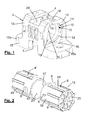
- FIG. 1 depicts a guide body 2 formed by a single part molded in plastic and provided with a through hole 4, with a rectangular cross section and intended to guide the retaining rod, and with two side holes 24 and 24' connecting the outside of the guide body 2 with the through hole 4.
- the side holes 24 and 24' are axially aligned and are perpendicular to the direction followed by the through hole 4.
- the guide body 2 is provided with two diametrically opposite flanges 15a and 15b, each of which extends on a side of the through hole 4, which determine a support plate 15 for the stable support of the guide body 2 on a planar surface of the door of the vehicle and in which respective metal components 16 for the fixing of the guide body 2 are embedded.
- a respective nut is embedded inside each of the flanges 15a and 15b, and it can be observed that said nuts are aligned and are arranged immediately below the receptacles 8 and 8' once the latter are duly coupled to the guide body 2. Since the guide body 2 lacks parts for housing the brake means, the mentioned metal components 16 are accessible and can be secured without difficulty on both sides of the support plate 15 during the manufacture of the guide body 2, being completely locked without needing to use a threaded tool to prevent the movement thereof in the axial direction during the overmolding of said components. Although it is not depicted, it is envisaged that in an alternative variant the metal components 16 are formed by screws or equivalent elements overmolded during the manufacture of the guide body 2.
- each of the side holes 24, 24' of the guide body 2 is prepared to receive the bayonet coupling of a corresponding receptacle 8 and 8', as has been depicted in Figure 3 .
- each side hole 24, 24' is provided with an annular channel 10 provided with four coupling portions 11, each of which is in turn provided with an access opening 12 and with a retaining portion 13, suitable for allowing the insertion and the retention, respectively, in said channel 10 of tabs 9 provided for such purpose in the vicinity of the mouth 17 of the receptacles 8 and 8', which can be reversibly or removably coupled to the guide body 2 upon rotating, after the tabs 9 have been introduced in the channel 10, towards the retaining portions 13.
- the guide body 2 has a series of access holes 18, through which the suitable tools can be introduced inside the mold of the part during its molding to occupy those spaces which will subsequently determine the annular channel 10.
- Figure 2 shows an embodiment variant of two receptacles 8, 8' intended to be plugged in the side holes 24, 24' of the guide body 2 of Figure 1 .
- the receptacles 8, 8' are provided, in the vicinity of their mouth 17, with the outwardly oriented transverse tabs 9, which are introduced in the retaining portions 13 of the annular channel 10 of the side holes 24, 24' of the guide body 2.
- the depicted receptacles 8, 8' are provided in their outer surface with a series of longitudinal reinforcement ribs 19 extending from the transverse tabs 9 towards the opposite end of each receptacle. It is furthermore observed that the closed end 20 of the receptacles 8, 8' is provided with means for the coupling under pressure of a protective cover of the device 1.
- the receptacles 8, 8' are furthermore provided with a respective upper flange 21, intended to prevent the forced movement of stop means 22, formed by respective bodies of rubber or the like, occasionally placed in the mouth of the through hole 4 of the guide body 2 to prevent the direct contact between the terminal of the retaining rod 3 and the guide body in the maximum opening position of the door of the vehicle, a situation is depicted in Figure 4 .
- the receptacles 8, 8' are formed by tubular bodies closed at one of their ends and they preferably have a circular inner cross-section to allow the free rotation of the brake body 6 housed therein.
- Figure 4 depicts the receptacle 8 in a fitted position, leaving exposed the components of the brake means 5 housed therein, formed in a known manner by the mentioned brake body 6 and a respective compression spring 7 which, supported against the closed end 20 of the receptacle 8, exerts a thrusting force on said brake body 6 towards the retaining rod 3.
- the assembly of the device 1 is very simple in practice, since it does not require complementary elements for the mutual fixing of the parts forming the housing 23. Furthermore, since the guide body 2 lacks not provided with parts intended to guide or contain the brake means, the manufacture thereof is facilitated and fixing means can be overinjected which, once the housing 23 is assembled, are arranged in the same plane of movement of the brake bodies and normal to the support surface of the guide body.
- each retaining portion 13 of the channel 10 being widened in the coupling direction of the receptacles 8, 8', or provide the mentioned retaining portions with a width greater than that of the height of the tabs 9, providing in turn the outer wall 25 of the channel 10, in at least one section of access to a retaining portion 13, with a rib or protuberance 26 (see Figure 5 ) which acts like a stop, preventing the rotation of the receptacles 8, 8' in the direction opposite that of their coupling if the thrusting force exerted thereon by the associated compression spring is not previously overcome.
Landscapes
- Engineering & Computer Science (AREA)
- Mechanical Engineering (AREA)
- Braking Arrangements (AREA)
- Closing And Opening Devices For Wings, And Checks For Wings (AREA)
- Lock And Its Accessories (AREA)
- Vehicle Step Arrangements And Article Storage (AREA)
Applications Claiming Priority (1)
| Application Number | Priority Date | Filing Date | Title |
|---|---|---|---|
| ES201030079A ES2396636B1 (es) | 2010-01-22 | 2010-01-22 | Dispositivo retenedor de puerta. |
Publications (3)
| Publication Number | Publication Date |
|---|---|
| EP2348178A2 true EP2348178A2 (de) | 2011-07-27 |
| EP2348178A3 EP2348178A3 (de) | 2013-07-10 |
| EP2348178B1 EP2348178B1 (de) | 2015-05-06 |
Family
ID=43920921
Family Applications (1)
| Application Number | Title | Priority Date | Filing Date |
|---|---|---|---|
| EP20100382343 Active EP2348178B1 (de) | 2010-01-22 | 2010-12-22 | Türfeststellvorrichtung |
Country Status (3)
| Country | Link |
|---|---|
| US (1) | US8424159B2 (de) |
| EP (1) | EP2348178B1 (de) |
| ES (2) | ES2396636B1 (de) |
Cited By (2)
| Publication number | Priority date | Publication date | Assignee | Title |
|---|---|---|---|---|
| CN106471198A (zh) * | 2014-07-09 | 2017-03-01 | 沃伦工业股份有限公司 | 用于车门限位臂组件的限位臂定位器的改进结构 |
| EP2808473B1 (de) * | 2013-05-27 | 2019-07-17 | AKA Automotiv S.R.L. | Gestufter Türstopper |
Families Citing this family (4)
| Publication number | Priority date | Publication date | Assignee | Title |
|---|---|---|---|---|
| FR2957624B1 (fr) * | 2010-03-17 | 2021-01-22 | Exsto | Dispositif d’ecartement d’un element ouvrant par rapport a un element fixe, notamment d’un vehicule automobile |
| US9068388B2 (en) * | 2013-04-30 | 2015-06-30 | GM Global Technology Operations LLC | Strain distribution check link assembly |
| WO2015146754A1 (ja) * | 2014-03-26 | 2015-10-01 | アイシン精機 株式会社 | ドア開度調整装置 |
| JP6800177B2 (ja) * | 2018-04-23 | 2020-12-16 | 三井金属アクト株式会社 | 自動車用ドアチェック装置 |
Citations (4)
| Publication number | Priority date | Publication date | Assignee | Title |
|---|---|---|---|---|
| US6842943B2 (en) | 2000-05-20 | 2005-01-18 | Edscha Ag | Pressure-ball sliding doorstop |
| EP1588006A1 (de) | 2003-01-22 | 2005-10-26 | Edscha AG | Türfeststeller |
| WO2007031073A2 (de) | 2005-09-15 | 2007-03-22 | Edscha Ag | Türfeststeller mit haltergehäuse |
| WO2007057332A1 (de) | 2005-11-15 | 2007-05-24 | Friedr. Fingscheidt Gmbh | Türhalter für fahrzeugtüren |
Family Cites Families (10)
| Publication number | Priority date | Publication date | Assignee | Title |
|---|---|---|---|---|
| US5474344A (en) * | 1994-03-30 | 1995-12-12 | Bloxwich Korea Co., Ltd. | Multi-stage door opening device |
| DE19745928C2 (de) * | 1997-10-17 | 2001-04-26 | Audi Ag | Türfeststeller an einer Kraftfahrzeugtür |
| DE10302549B4 (de) * | 2003-01-22 | 2013-05-08 | Edscha Engineering Gmbh | Türfeststeller |
| JP2004316299A (ja) * | 2003-04-17 | 2004-11-11 | Riken Kaki Kogyo Kk | 自動車用ドアチェッカ |
| US7793387B2 (en) * | 2004-08-30 | 2010-09-14 | M.T.M. Pty Ltd. | Door check |
| DE202005003287U1 (de) * | 2005-02-25 | 2005-06-16 | Edscha Ag | Türfeststeller |
| ITMI20050419A1 (it) * | 2005-03-15 | 2006-09-16 | Agostino Ferrari Spa | Dispositivo ammortizzante per elementi di arredaento con sistema di compensazione della variazione di volume migliorato |
| CN101285363B (zh) * | 2007-02-01 | 2012-04-18 | 通用汽车环球科技运作公司 | 门致动系统 |
| DE102007023110A1 (de) * | 2007-02-01 | 2008-08-07 | Edscha Ag | Türfeststeller |
| DE102007029707A1 (de) * | 2007-06-27 | 2009-01-08 | Audi Ag | Vorrichtung zur Arretierung einer Kraftfahrzeugtür |
-
2010
- 2010-01-22 ES ES201030079A patent/ES2396636B1/es not_active Expired - Fee Related
- 2010-07-13 US US12/835,326 patent/US8424159B2/en not_active Expired - Fee Related
- 2010-12-22 EP EP20100382343 patent/EP2348178B1/de active Active
- 2010-12-22 ES ES10382343.1T patent/ES2543653T3/es active Active
Patent Citations (4)
| Publication number | Priority date | Publication date | Assignee | Title |
|---|---|---|---|---|
| US6842943B2 (en) | 2000-05-20 | 2005-01-18 | Edscha Ag | Pressure-ball sliding doorstop |
| EP1588006A1 (de) | 2003-01-22 | 2005-10-26 | Edscha AG | Türfeststeller |
| WO2007031073A2 (de) | 2005-09-15 | 2007-03-22 | Edscha Ag | Türfeststeller mit haltergehäuse |
| WO2007057332A1 (de) | 2005-11-15 | 2007-05-24 | Friedr. Fingscheidt Gmbh | Türhalter für fahrzeugtüren |
Cited By (4)
| Publication number | Priority date | Publication date | Assignee | Title |
|---|---|---|---|---|
| EP2808473B1 (de) * | 2013-05-27 | 2019-07-17 | AKA Automotiv S.R.L. | Gestufter Türstopper |
| CN106471198A (zh) * | 2014-07-09 | 2017-03-01 | 沃伦工业股份有限公司 | 用于车门限位臂组件的限位臂定位器的改进结构 |
| EP3167133A4 (de) * | 2014-07-09 | 2018-03-28 | Warren Industries Ltd. | Verbesserte konstruktion für einen feststellerhalter für die feststelleranordnung für eine fahrzeugtür |
| US10415280B2 (en) | 2014-07-09 | 2019-09-17 | Warren Industries Ltd. | Construction for check arm keeper for check arm assembly for vehicle door |
Also Published As
| Publication number | Publication date |
|---|---|
| US20110179599A1 (en) | 2011-07-28 |
| ES2396636A1 (es) | 2013-02-25 |
| ES2543653T3 (es) | 2015-08-20 |
| EP2348178B1 (de) | 2015-05-06 |
| ES2396636B1 (es) | 2014-01-07 |
| EP2348178A3 (de) | 2013-07-10 |
| US8424159B2 (en) | 2013-04-23 |
Similar Documents
| Publication | Publication Date | Title |
|---|---|---|
| EP2348178B1 (de) | Türfeststellvorrichtung | |
| US10034524B2 (en) | Umbrella quick frame assembly systems and methods | |
| DE102012014318B4 (de) | Federfunktionsbauteil für ein hydroelastisches Lager und hydroelastisches Lager | |
| DE102013224295B4 (de) | Zentralausrücker für eine Kupplung | |
| EP1745540B1 (de) | Elektromotor und getriebe-antriebseinheit für stellantriebe im kraftfahrzeug | |
| EP2530799A2 (de) | Vorrichtung zum dichtenden Verschliessen eines Kabelschutzrohrendes | |
| WO2012116383A1 (de) | VORRICHTUNG ZUM ÖFFNEN BZW. SCHLIEßEN EINER TÜR SOWIE VERFAHREN ZUR MONTAGE EINER SOLCHEN VORRICHTUNG | |
| EP3050816B1 (de) | Palette mit sicherungselementen | |
| EP2220510A2 (de) | Verfahren zur herstellung eines magnetfeldsensors und nach dem verfahren hergestellter sensor | |
| EP2065628B1 (de) | Anordnung mit einem Verbindungselement für eine Rohrkupplung | |
| EP2980425B1 (de) | Befestigungsanordnung für c-förmige halteschienen und bausatz | |
| DE202010002387U1 (de) | Saugkorb | |
| DE102015010055A1 (de) | Hydraulikzylinder, insbesondere Nehmerzylinder für eine hydraulische Kupplungsbetätigung für Kraftfahrzeuge | |
| DE102007014508A1 (de) | Spuleneinrichtung für Draht, insbesondere für Schweißdraht | |
| DE102012000215A1 (de) | Rückschlagventil | |
| DE102011054955A1 (de) | Rotorbaugruppe eines Gleichstrommotors | |
| MX2007005257A (es) | Grupo de montaje con cierre liberable. | |
| DE202005021617U1 (de) | Biegefeste Kolbenzylindereinheit | |
| DE102007028716A1 (de) | Hydraulisches Spannelement für einen Zugmitteltrieb | |
| DE102014103593A1 (de) | Verbesserter Gleichstrom-Getriebeelektromotor für Fensterheber, Sitze, Scheibenwischer und andere Einrichtungen in Kraftfahrzeugen | |
| EP3203952B1 (de) | Passiver gehörschutz, damit ausgestattetes ohrpassstück und verfahren zu dessen herstellung | |
| EP2585743A1 (de) | Rückschlagventil für eine fluidpumpe | |
| EP2103763B1 (de) | Rohrförmiger Griff für Türen und Fenster | |
| DE102009053760A1 (de) | Abschirmvorrichtung für eine Lenkspindel | |
| DE102007038522A1 (de) | Statorbefestigung mittels Spannpratzen |
Legal Events
| Date | Code | Title | Description |
|---|---|---|---|
| PUAI | Public reference made under article 153(3) epc to a published international application that has entered the european phase |
Free format text: ORIGINAL CODE: 0009012 |
|
| AK | Designated contracting states |
Kind code of ref document: A2 Designated state(s): AL AT BE BG CH CY CZ DE DK EE ES FI FR GB GR HR HU IE IS IT LI LT LU LV MC MK MT NL NO PL PT RO RS SE SI SK SM TR |
|
| AX | Request for extension of the european patent |
Extension state: BA ME |
|
| PUAL | Search report despatched |
Free format text: ORIGINAL CODE: 0009013 |
|
| AK | Designated contracting states |
Kind code of ref document: A3 Designated state(s): AL AT BE BG CH CY CZ DE DK EE ES FI FR GB GR HR HU IE IS IT LI LT LU LV MC MK MT NL NO PL PT RO RS SE SI SK SM TR |
|
| AX | Request for extension of the european patent |
Extension state: BA ME |
|
| RIC1 | Information provided on ipc code assigned before grant |
Ipc: E05C 17/20 20060101AFI20130603BHEP |
|
| 17P | Request for examination filed |
Effective date: 20131212 |
|
| RBV | Designated contracting states (corrected) |
Designated state(s): AL AT BE BG CH CY CZ DE DK EE ES FI FR GB GR HR HU IE IS IT LI LT LU LV MC MK MT NL NO PL PT RO RS SE SI SK SM TR |
|
| GRAP | Despatch of communication of intention to grant a patent |
Free format text: ORIGINAL CODE: EPIDOSNIGR1 |
|
| INTG | Intention to grant announced |
Effective date: 20141209 |
|
| GRAS | Grant fee paid |
Free format text: ORIGINAL CODE: EPIDOSNIGR3 |
|
| GRAA | (expected) grant |
Free format text: ORIGINAL CODE: 0009210 |
|
| AK | Designated contracting states |
Kind code of ref document: B1 Designated state(s): AL AT BE BG CH CY CZ DE DK EE ES FI FR GB GR HR HU IE IS IT LI LT LU LV MC MK MT NL NO PL PT RO RS SE SI SK SM TR |
|
| REG | Reference to a national code |
Ref country code: GB Ref legal event code: FG4D |
|
| REG | Reference to a national code |
Ref country code: CH Ref legal event code: EP |
|
| REG | Reference to a national code |
Ref country code: IE Ref legal event code: FG4D |
|
| REG | Reference to a national code |
Ref country code: AT Ref legal event code: REF Ref document number: 725831 Country of ref document: AT Kind code of ref document: T Effective date: 20150615 |
|
| REG | Reference to a national code |
Ref country code: DE Ref legal event code: R096 Ref document number: 602010024446 Country of ref document: DE Effective date: 20150618 |
|
| REG | Reference to a national code |
Ref country code: ES Ref legal event code: FG2A Ref document number: 2543653 Country of ref document: ES Kind code of ref document: T3 Effective date: 20150820 |
|
| REG | Reference to a national code |
Ref country code: AT Ref legal event code: MK05 Ref document number: 725831 Country of ref document: AT Kind code of ref document: T Effective date: 20150506 |
|
| REG | Reference to a national code |
Ref country code: NL Ref legal event code: MP Effective date: 20150506 |
|
| REG | Reference to a national code |
Ref country code: LT Ref legal event code: MG4D |
|
| PG25 | Lapsed in a contracting state [announced via postgrant information from national office to epo] |
Ref country code: HR Free format text: LAPSE BECAUSE OF FAILURE TO SUBMIT A TRANSLATION OF THE DESCRIPTION OR TO PAY THE FEE WITHIN THE PRESCRIBED TIME-LIMIT Effective date: 20150506 Ref country code: PT Free format text: LAPSE BECAUSE OF FAILURE TO SUBMIT A TRANSLATION OF THE DESCRIPTION OR TO PAY THE FEE WITHIN THE PRESCRIBED TIME-LIMIT Effective date: 20150907 Ref country code: NO Free format text: LAPSE BECAUSE OF FAILURE TO SUBMIT A TRANSLATION OF THE DESCRIPTION OR TO PAY THE FEE WITHIN THE PRESCRIBED TIME-LIMIT Effective date: 20150806 Ref country code: FI Free format text: LAPSE BECAUSE OF FAILURE TO SUBMIT A TRANSLATION OF THE DESCRIPTION OR TO PAY THE FEE WITHIN THE PRESCRIBED TIME-LIMIT Effective date: 20150506 Ref country code: LT Free format text: LAPSE BECAUSE OF FAILURE TO SUBMIT A TRANSLATION OF THE DESCRIPTION OR TO PAY THE FEE WITHIN THE PRESCRIBED TIME-LIMIT Effective date: 20150506 |
|
| REG | Reference to a national code |
Ref country code: FR Ref legal event code: PLFP Year of fee payment: 6 |
|
| PG25 | Lapsed in a contracting state [announced via postgrant information from national office to epo] |
Ref country code: BG Free format text: LAPSE BECAUSE OF FAILURE TO SUBMIT A TRANSLATION OF THE DESCRIPTION OR TO PAY THE FEE WITHIN THE PRESCRIBED TIME-LIMIT Effective date: 20150806 Ref country code: LV Free format text: LAPSE BECAUSE OF FAILURE TO SUBMIT A TRANSLATION OF THE DESCRIPTION OR TO PAY THE FEE WITHIN THE PRESCRIBED TIME-LIMIT Effective date: 20150506 Ref country code: RS Free format text: LAPSE BECAUSE OF FAILURE TO SUBMIT A TRANSLATION OF THE DESCRIPTION OR TO PAY THE FEE WITHIN THE PRESCRIBED TIME-LIMIT Effective date: 20150506 Ref country code: GR Free format text: LAPSE BECAUSE OF FAILURE TO SUBMIT A TRANSLATION OF THE DESCRIPTION OR TO PAY THE FEE WITHIN THE PRESCRIBED TIME-LIMIT Effective date: 20150807 Ref country code: AT Free format text: LAPSE BECAUSE OF FAILURE TO SUBMIT A TRANSLATION OF THE DESCRIPTION OR TO PAY THE FEE WITHIN THE PRESCRIBED TIME-LIMIT Effective date: 20150506 Ref country code: IS Free format text: LAPSE BECAUSE OF FAILURE TO SUBMIT A TRANSLATION OF THE DESCRIPTION OR TO PAY THE FEE WITHIN THE PRESCRIBED TIME-LIMIT Effective date: 20150906 |
|
| PG25 | Lapsed in a contracting state [announced via postgrant information from national office to epo] |
Ref country code: EE Free format text: LAPSE BECAUSE OF FAILURE TO SUBMIT A TRANSLATION OF THE DESCRIPTION OR TO PAY THE FEE WITHIN THE PRESCRIBED TIME-LIMIT Effective date: 20150506 Ref country code: DK Free format text: LAPSE BECAUSE OF FAILURE TO SUBMIT A TRANSLATION OF THE DESCRIPTION OR TO PAY THE FEE WITHIN THE PRESCRIBED TIME-LIMIT Effective date: 20150506 |
|
| REG | Reference to a national code |
Ref country code: DE Ref legal event code: R097 Ref document number: 602010024446 Country of ref document: DE |
|
| PG25 | Lapsed in a contracting state [announced via postgrant information from national office to epo] |
Ref country code: CZ Free format text: LAPSE BECAUSE OF FAILURE TO SUBMIT A TRANSLATION OF THE DESCRIPTION OR TO PAY THE FEE WITHIN THE PRESCRIBED TIME-LIMIT Effective date: 20150506 Ref country code: RO Free format text: LAPSE BECAUSE OF NON-PAYMENT OF DUE FEES Effective date: 20150506 Ref country code: PL Free format text: LAPSE BECAUSE OF FAILURE TO SUBMIT A TRANSLATION OF THE DESCRIPTION OR TO PAY THE FEE WITHIN THE PRESCRIBED TIME-LIMIT Effective date: 20150506 Ref country code: SK Free format text: LAPSE BECAUSE OF FAILURE TO SUBMIT A TRANSLATION OF THE DESCRIPTION OR TO PAY THE FEE WITHIN THE PRESCRIBED TIME-LIMIT Effective date: 20150506 |
|
| PLBE | No opposition filed within time limit |
Free format text: ORIGINAL CODE: 0009261 |
|
| STAA | Information on the status of an ep patent application or granted ep patent |
Free format text: STATUS: NO OPPOSITION FILED WITHIN TIME LIMIT |
|
| 26N | No opposition filed |
Effective date: 20160209 |
|
| PG25 | Lapsed in a contracting state [announced via postgrant information from national office to epo] |
Ref country code: BE Free format text: LAPSE BECAUSE OF NON-PAYMENT OF DUE FEES Effective date: 20151231 Ref country code: SI Free format text: LAPSE BECAUSE OF FAILURE TO SUBMIT A TRANSLATION OF THE DESCRIPTION OR TO PAY THE FEE WITHIN THE PRESCRIBED TIME-LIMIT Effective date: 20150506 |
|
| PG25 | Lapsed in a contracting state [announced via postgrant information from national office to epo] |
Ref country code: MC Free format text: LAPSE BECAUSE OF FAILURE TO SUBMIT A TRANSLATION OF THE DESCRIPTION OR TO PAY THE FEE WITHIN THE PRESCRIBED TIME-LIMIT Effective date: 20150506 Ref country code: LU Free format text: LAPSE BECAUSE OF FAILURE TO SUBMIT A TRANSLATION OF THE DESCRIPTION OR TO PAY THE FEE WITHIN THE PRESCRIBED TIME-LIMIT Effective date: 20151222 |
|
| REG | Reference to a national code |
Ref country code: CH Ref legal event code: PL |
|
| PG25 | Lapsed in a contracting state [announced via postgrant information from national office to epo] |
Ref country code: BE Free format text: LAPSE BECAUSE OF FAILURE TO SUBMIT A TRANSLATION OF THE DESCRIPTION OR TO PAY THE FEE WITHIN THE PRESCRIBED TIME-LIMIT Effective date: 20150506 |
|
| REG | Reference to a national code |
Ref country code: IE Ref legal event code: MM4A |
|
| PG25 | Lapsed in a contracting state [announced via postgrant information from national office to epo] |
Ref country code: LI Free format text: LAPSE BECAUSE OF NON-PAYMENT OF DUE FEES Effective date: 20151231 Ref country code: CH Free format text: LAPSE BECAUSE OF NON-PAYMENT OF DUE FEES Effective date: 20151231 Ref country code: IE Free format text: LAPSE BECAUSE OF NON-PAYMENT OF DUE FEES Effective date: 20151222 |
|
| REG | Reference to a national code |
Ref country code: FR Ref legal event code: PLFP Year of fee payment: 7 |
|
| PG25 | Lapsed in a contracting state [announced via postgrant information from national office to epo] |
Ref country code: SM Free format text: LAPSE BECAUSE OF FAILURE TO SUBMIT A TRANSLATION OF THE DESCRIPTION OR TO PAY THE FEE WITHIN THE PRESCRIBED TIME-LIMIT Effective date: 20150506 Ref country code: HU Free format text: LAPSE BECAUSE OF FAILURE TO SUBMIT A TRANSLATION OF THE DESCRIPTION OR TO PAY THE FEE WITHIN THE PRESCRIBED TIME-LIMIT; INVALID AB INITIO Effective date: 20101222 |
|
| PG25 | Lapsed in a contracting state [announced via postgrant information from national office to epo] |
Ref country code: NL Free format text: LAPSE BECAUSE OF FAILURE TO SUBMIT A TRANSLATION OF THE DESCRIPTION OR TO PAY THE FEE WITHIN THE PRESCRIBED TIME-LIMIT Effective date: 20150506 Ref country code: SE Free format text: LAPSE BECAUSE OF FAILURE TO SUBMIT A TRANSLATION OF THE DESCRIPTION OR TO PAY THE FEE WITHIN THE PRESCRIBED TIME-LIMIT Effective date: 20150506 Ref country code: CY Free format text: LAPSE BECAUSE OF FAILURE TO SUBMIT A TRANSLATION OF THE DESCRIPTION OR TO PAY THE FEE WITHIN THE PRESCRIBED TIME-LIMIT Effective date: 20150506 |
|
| PG25 | Lapsed in a contracting state [announced via postgrant information from national office to epo] |
Ref country code: MT Free format text: LAPSE BECAUSE OF FAILURE TO SUBMIT A TRANSLATION OF THE DESCRIPTION OR TO PAY THE FEE WITHIN THE PRESCRIBED TIME-LIMIT Effective date: 20150506 Ref country code: TR Free format text: LAPSE BECAUSE OF FAILURE TO SUBMIT A TRANSLATION OF THE DESCRIPTION OR TO PAY THE FEE WITHIN THE PRESCRIBED TIME-LIMIT Effective date: 20150506 |
|
| REG | Reference to a national code |
Ref country code: FR Ref legal event code: PLFP Year of fee payment: 8 |
|
| PG25 | Lapsed in a contracting state [announced via postgrant information from national office to epo] |
Ref country code: MK Free format text: LAPSE BECAUSE OF FAILURE TO SUBMIT A TRANSLATION OF THE DESCRIPTION OR TO PAY THE FEE WITHIN THE PRESCRIBED TIME-LIMIT Effective date: 20150506 |
|
| PG25 | Lapsed in a contracting state [announced via postgrant information from national office to epo] |
Ref country code: AL Free format text: LAPSE BECAUSE OF FAILURE TO SUBMIT A TRANSLATION OF THE DESCRIPTION OR TO PAY THE FEE WITHIN THE PRESCRIBED TIME-LIMIT Effective date: 20150506 |
|
| PGFP | Annual fee paid to national office [announced via postgrant information from national office to epo] |
Ref country code: FR Payment date: 20250929 Year of fee payment: 16 |
|
| PGFP | Annual fee paid to national office [announced via postgrant information from national office to epo] |
Ref country code: GB Payment date: 20251216 Year of fee payment: 16 |
|
| PGFP | Annual fee paid to national office [announced via postgrant information from national office to epo] |
Ref country code: IT Payment date: 20251203 Year of fee payment: 16 |
|
| PGFP | Annual fee paid to national office [announced via postgrant information from national office to epo] |
Ref country code: ES Payment date: 20260126 Year of fee payment: 16 |
|
| PGFP | Annual fee paid to national office [announced via postgrant information from national office to epo] |
Ref country code: DE Payment date: 20251222 Year of fee payment: 16 |