EP2348188A2 - Dispositif de basculement et procédé de réglage de la position de travail d'un store vénitien - Google Patents
Dispositif de basculement et procédé de réglage de la position de travail d'un store vénitien Download PDFInfo
- Publication number
- EP2348188A2 EP2348188A2 EP10405201A EP10405201A EP2348188A2 EP 2348188 A2 EP2348188 A2 EP 2348188A2 EP 10405201 A EP10405201 A EP 10405201A EP 10405201 A EP10405201 A EP 10405201A EP 2348188 A2 EP2348188 A2 EP 2348188A2
- Authority
- EP
- European Patent Office
- Prior art keywords
- turning
- stop
- locking
- slats
- turning device
- Prior art date
- Legal status (The legal status is an assumption and is not a legal conclusion. Google has not performed a legal analysis and makes no representation as to the accuracy of the status listed.)
- Withdrawn
Links
Images


Classifications
-
- E—FIXED CONSTRUCTIONS
- E06—DOORS, WINDOWS, SHUTTERS, OR ROLLER BLINDS IN GENERAL; LADDERS
- E06B—FIXED OR MOVABLE CLOSURES FOR OPENINGS IN BUILDINGS, VEHICLES, FENCES OR LIKE ENCLOSURES IN GENERAL, e.g. DOORS, WINDOWS, BLINDS, GATES
- E06B9/00—Screening or protective devices for wall or similar openings, with or without operating or securing mechanisms; Closures of similar construction
- E06B9/24—Screens or other constructions affording protection against light, especially against sunshine; Similar screens for privacy or appearance; Slat blinds
- E06B9/26—Lamellar or like blinds, e.g. venetian blinds
- E06B9/28—Lamellar or like blinds, e.g. venetian blinds with horizontal lamellae, e.g. non-liftable
- E06B9/30—Lamellar or like blinds, e.g. venetian blinds with horizontal lamellae, e.g. non-liftable liftable
- E06B9/303—Lamellar or like blinds, e.g. venetian blinds with horizontal lamellae, e.g. non-liftable liftable with ladder-tape
- E06B9/307—Details of tilting bars and their operation
-
- E—FIXED CONSTRUCTIONS
- E06—DOORS, WINDOWS, SHUTTERS, OR ROLLER BLINDS IN GENERAL; LADDERS
- E06B—FIXED OR MOVABLE CLOSURES FOR OPENINGS IN BUILDINGS, VEHICLES, FENCES OR LIKE ENCLOSURES IN GENERAL, e.g. DOORS, WINDOWS, BLINDS, GATES
- E06B9/00—Screening or protective devices for wall or similar openings, with or without operating or securing mechanisms; Closures of similar construction
- E06B9/24—Screens or other constructions affording protection against light, especially against sunshine; Similar screens for privacy or appearance; Slat blinds
- E06B9/26—Lamellar or like blinds, e.g. venetian blinds
- E06B9/28—Lamellar or like blinds, e.g. venetian blinds with horizontal lamellae, e.g. non-liftable
- E06B9/30—Lamellar or like blinds, e.g. venetian blinds with horizontal lamellae, e.g. non-liftable liftable
- E06B9/303—Lamellar or like blinds, e.g. venetian blinds with horizontal lamellae, e.g. non-liftable liftable with ladder-tape
- E06B9/308—Lamellar or like blinds, e.g. venetian blinds with horizontal lamellae, e.g. non-liftable liftable with ladder-tape with coaxial tilting bar and raising shaft
Definitions
- the invention relates to a turning device and a method for adjusting the working position in a Rafflamellenstore according to the preamble of claims 1 and 11.
- Rafflamellenstoren include a curtain with elongated, within a building recess horizontally oriented and stackable on a vertically movable mounting rail slats. In the region of the upper edge of the building recess extending between the lateral boundary walls a parallel to the slats and the support rail aligned drive shaft. This is connected to a drive arrangement for raising and lowering the mounting rail. When lifting the mounting rail, the slats are stacked one after another on the mounting rail, stacked when lowering of this.
- the drive shaft can be driven - controlled by a controller - by an electric motor. Alternatively, hand cranks for driving the drive shaft are known.
- the drive arrangement can comprise, for example, two or more coils, which are pushed onto the drive shaft, distributed over the length thereof and non-rotatably connected with the latter.
- Each of these coils comprises coaxially with the drive shaft a spool core, on the periphery of which one end of an elevator belt is attached.
- the respective other ends of these elevator belts are looped through corresponding passage openings in the slats and connected to the support rail.
- guide pins are formed on the two opposite narrow sides of the slats and the mounting rail. These engage in vertical guide rails which are fastened to the side walls of the building recess. They allow a guided movement of the mounting rail and the slats within the building recess.
- the means for raising and lowering the mounting rail can also be partially or completely formed in the region of the vertical guide rails.
- endless drive belts, drive chains or other drive means can be provided there, for example, each at the top around a drive wheel coupled to the drive shaft are led around.
- drive means may be guided around a further deflecting element in the region of the lower end of the guide rails.
- the lamellae are connected in the region of their two longitudinal edges with two or more carrying or turning belts, said turning belts are arranged transversely to the lamellae.
- the joints connected with adjacent fins are arranged at regular intervals.
- Each turning belt is connected to a pivotable turning body of a turning mechanism arranged above the lamellae. By jointly pivoting this turning body of the position or inclination angle of those slats that hang on the turning belts or are not stacked on the support rail, can be changed synchronously.
- the turning body may, for example, have the shape of a rotatably mounted within a reversing housing wheel with a peripheral, circumferential guide groove.
- Each turning belt is looped around the respective associated wheel, wherein the two drooping strands of this turning band are connected on both sides with the opposite longitudinal edges of each of the slats.
- Anti-slip such as a positive local connection of the turning belt and the wheel prevents the turning belt and the periphery of the wheel can move relative to each other.
- turning devices are known in which instead of a wheel generally a rocker and / or instead of a rotating turning belt two separate Wendebandabitese are provided.
- the pivoting range of the turning body is dimensioned such that the position angle of the hanging on the turning belts slats of the curtain between a closed position and an open position can be changed continuously.
- adjacent slats overlap in a scale-like manner, so that the building recess in the area of these slats is covered as best as possible.
- the slats at the respective lowering position of the mounting rail release the largest possible cross-section of the building opening.
- the turning mechanism usually includes a wrap spring clutch.
- a wrap spring is pushed onto the drive shaft or on a rotatably connected to the drive shaft coupling body and non-positively connected due to the bias of the wrap.
- the wrap spring comprises two angled, radially outwardly projecting end legs. These are used as a driver for pivoting the pivoting body. At the reversing housing two stops for the end legs of the wrap spring are formed.
- the wrap spring is coupled to the drive shaft and transmits their rotational movement as long as on the swivel body until the first end leg abuts against the winding direction on the corresponding first stop. In this pivoting position, the slats of the curtain are in the open position.
- the drive shaft continues to rotate, the torque exerted by the first stop on the wrap spring effects a release of the frictional connection between the wrap spring and the drive shaft.
- the positional angle no longer changes and the slats are stacked in sequence on the support rail.
- the drive shaft is rotated in opposite directions of rotation.
- the wrap spring is coupled to the drive shaft and transmits its rotational movement as long as on the swivel body until the second end leg abuts against the winding direction on the corresponding second stop. In this pivotal position, the slats of the curtain, which are no longer stacked on the mounting rail, in the closed position.
- the third stop at which the second end leg of the wrap spring is present, is replaced with a changeover device by the second stop.
- the third stop may be, for example, a spring-mounted locking lug, which is pressed against the spring force acting on the detent when the drive shaft is rotated by a wedge-like actuating element of the changeover device to the side.
- a spring-loaded pawl may be used, which protrudes at the periphery of the bobbin.
- the pawl may be rigidly or otherwise mechanically connected or coupled to the actuating element, this actuating element being used for influencing the position or the effect of the third stop.
- the actuating element In this pawl position, the actuating element is positioned so that it can not change the position of the third stop and its effect on the second end leg.
- the slats remain in working position when the support rail is lowered. If the DIN rail exceeds the AB1 position during lowering, the innermost winding layer of the elevator belt is present the latch free.
- the pawl pivots radially outward due to the acting spring force.
- the trained on the latch or coupled to the pawl actuator moves from a passive position into an active position.
- the actuating element urges the spring-mounted locking lug or the third stop against the restoring spring force to the side.
- the third stop thus acts at least temporarily no longer as a barrier for the second end leg of the wrap.
- the turning body or the wrap spring is again coupled to the drive shaft and the further rotation of the drive shaft, the slats are pivoted from the working position into the closed position.
- the slats are pivoted in an analogous manner again in the open position, which is determined by the angular position of the first stop for the first end leg of the wrap. Since the third stop is formed as a sawtooth-like locking lug and is resiliently mounted, the actuating element can pass similar to a freewheel. The pivoting of the slats is not hindered.
- a disadvantage of such known turning devices with working position function is the specification of a fixed angle of inclination of the slats for the working position. Furthermore, the slats of the blind can only at completely lowered support rail are completely closed.
- Another object of the invention is to design the turning device so that a simple and flexible adjustment of the angle of inclination of the slats in the working position is possible.
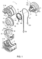
- FIG. 1 shows an exploded view of a turning mechanism 1, as known from the prior art.
- the turning mechanism 1 comprises a housing 3 with two attachable housing halves 3a, 3b, which can be fastened to one another by means of latching connecting elements.
- Semicircular recesses 5 are formed on the two side walls of each of these housing halves 3a, 3b, which serve for rotatably supporting a coil 7 when the housing 3 is assembled.
- the coil 7 comprises a continuous hollow shaft 9, the inner cross section of the outer cross section of a motor or by the hand crank driven elevator shaft of the store (not shown) is adapted, such that the coil 7 can be pushed onto this elevator shaft and rotatably connected with it.
- the spool 7 Adjacent to one of the two lateral boundary walls 11 of the coil 7, between which the respective elevator belt can be unwound or unwound, the spool 7 comprises a stub shaft 13.
- the outer diameter of a front portion 13a of this stub shaft 13 is larger than the outer diameter of the hollow shaft 9 and slightly smaller than that of a rear portion 13b adjacent to the front boundary wall 11.
- This wrap spring 15 comprises two radially outwardly projecting end legs 15a, 15b in different directions, such that these end legs 15a, 15b enclose an angle ⁇ when viewed axially, which may be, for example, of the order of approximately 15 ° to approximately 75 °.
- angle ⁇ when viewed axially, which may be, for example, of the order of approximately 15 ° to approximately 75 °.
- the turning body 17 comprises an annular collar 19 with a peripheral recess 21 through which the two end legs 15a, 15b of the wrap spring 15 project outwardly, and an axially adjoining the collar 19 and On the periphery of the turning wheel 23 a circumferential groove 25 is formed, in which a turning belt 27 is inserted.
- the turning belt 27 is connected locally to the turning wheel 23 at a tangential connection point. As in FIG. 1 shown, this connection can be done for example by means of a stationary on the turning belt 27 formed bead 29, which preferably can be releasably latched into a corresponding, slightly resilient receptacle 31 in the groove 25 again.
- the two hanging strands 27a, 27b of the turning belt 27 are connected in a known manner at regular intervals with the opposite longitudinal edges of each blade (not shown).
- the turning belt 27 may be integrally formed along its entire length or alternatively comprise a plurality of interconnected or connectable sections.
- the two sections of a turning belt 27 attached to the lamellae can be released again be connected to the strands 27a, 27b of the held on the turning wheel 23 portion (not shown).
- the front end leg 15a, 15b is used as a driver for the turning body 17 in accordance with the respective direction of rotation by exerting a torque on the respective adjacent edge of the recess 21 on the sleeve 19.
- the frictional connection between the wrap spring 15 and the front portion 13a of the stub shaft 13 is reinforced.
- the pivoting range of the turning body 17 is limited by rigidly connected to the housing 3 or formed directly on the housing 3 stops 33a, 33b for the rotational direction in each case rear end legs 15a, 15b of the wrap 15.
- the stops 33a, 33b are formed on a stop body 33 which can be pushed into the lower housing half 3a. As soon as each rear end leg 15a, 15b is pressed against the respectively associated stop 33a, 33b during rotation of the drive shaft, the non-positive connection between the wrap spring 15 and the stub shaft 13 is released due to the resulting torque.
- the Drive shaft are further rotated.
- the turning body 17 remains in the respective pivot position.
- the front stop 33a is arranged so that the turning body 17 when mounting the support rail, the open position of Slats pretends.
- the rear stop 33b determines when lowering the support rail by the associated pivot position of the turning body 17, the closed position of the slats.
- a further stop 33c is additionally provided in the case of blinds which have a so-called working position, in which the slats thus assume an angle of inclination or angle of attack when lowering the support rail, which is between that of the open position and that of the closed position.
- This further stop 33c can, as in FIG.
- a stop lever 35 represented as a front edge of a sawtooth-like latching nose with a beveled trailing edge 34 may be formed on a stop lever 35.
- This stop lever 35 comprises at one end a cylinder-like joint body 36 and at the opposite end a supported on the inner wall of the housing 3 and biased spring tongue 37.
- the stop lever 35 is pivotally mounted in the housing 3 transversely to the turning body 17. Due to the tension of the spring tongue 37, the intermediate stop 33c is pressed transversely to the movement path or from the side as a temporary barrier for the end leg 15a in its movement path.
- the stop 33c now acts as an active lock and retains the wrap spring 15 and thus also the reversing body 17 when lowering the mounting rail in a pivoting position which defines the working position of the lamellae.
- a temporary urges on the stop lever 35th acting Umstellstoff the stop 33c from the trajectory of the end leg 15a.
- the wrap spring 15 is therefore coupled again to the drive shaft or the stub shaft 13 and rotates the turning body 17 further until the end leg 15a is present at the rear stop 33b, which determines the pivot position of the turning body 17 for the closed position of the slats.
- the changeover means can, for example, be a wedge-like actuating element 39 (FIG.
- FIG. 2 which, for example, shortly before the support rail reaches the lowest lowered position is pivoted by spring force from a rest position into a live position.
- the actuating element 39 urges the stop lever 35 against the force of the spring tongue 37 to the side, so that the intermediate stop 33c clears the way for the further rotational movement of the end leg 15a of the wrap 15 and the lamellae can be pivoted into the closed position.
- the closing spring 15 is decoupled from the stub shaft 13 again.
- a lever-like wing 43 ( Fig. 2 ) of the band pawl 41 can be pivoted radially outwardly through a recess (not shown) on the core of the coil 7 such that it protrudes slightly radially beyond the coil core.
- a shaft stub 13 supported leaf spring (not shown)
- the wing 43 is pressed at fully unwound elevator belt in the coil space.
- the wing 43 is pivoted against the force of the leaf spring radially inwardly when pulling the support rail.
- FIG. 2 shows a cutaway turning mechanism 1 of a preferred embodiment of the inventive turning device.
- the pivot position of the turning body 17 can be locked in at least two different positions.
- a stop holder 45 is provided in the present example instead of the stop lever 35, which is the turning body 17 and its annular cuff 19th encased or clasped.
- the stopper holder 45 is frictionally held on the periphery of the sleeve 19.
- the stopper holder 45 can also be prevented by a braking or blocking device from turning with the turning body 17.
- shoulders 47a, 47b, 47c are laterally offset from one another on the stop holder 45. These paragraphs 47a, 47b, 47c may - as in FIG. 2 shown - formed by recesses or alternatively by outstanding areas in the stop holder 45.
- an actuator 51 is held on the housing 3.
- This actuator 51 preferably comprises an electromagnet with a parallel to the hollow shaft 9 and transversely to the stop holder 45 guided displaceably mounted bolt 53.
- a locking body 49 is fixed with an outstanding in the direction of the stop bracket 45 locking latch 49a.
- the bolt 53 is pressed in the inactive electromagnet by a prestressed return spring (not shown) axially in the direction of the stop bracket 45.
- a restriction device prevents the bolt 53 from being moved beyond a limit position.
- This limit position is dimensioned such that the locking bar 49a with suitable pivotal position of the stop holder 45 as a lock for the stop holder 45 in one of the recesses protrudes with the paragraphs 47a, 47b, 47c.
- the turning body 17 Upon further rotation of the turning body 17 in the closing direction of the respective paragraph 47a, 47b, 47c pressed against the locking bar 49a. Since the blocking or braking force of the locking bolt 49a is greater than the static friction between the stop bracket 45 and the sleeve 19, the turning body 17 can be further rotated.
- the stop holder 45 remains in its predetermined by the respective paragraph 47a, 47b, 47c pivot position.
- FIG. 3 shows the wrap spring 15, the turning body 17 and the stop bracket 45 in an exploded view.
- a groove-like further recess is formed on the opposite side of the stop holder 45, which surrounds at least a portion of the end leg 15a of the wrap 15 with little play.
- An interface of this recess forms for this end leg 15a the stop 33c, which is used to specify different working positions.
- the width s2 of the stopper holder 45 is approximately half the width s1 of the cuff 19. The range of motion of the end leg 15b farther from the stopper holder 45 is therefore not restricted by the stopper holder 45.
- the position of the paragraphs 47a, 47b, 47c thus defines the different pivotal positions of the slats in the respective working position.
- the closing position of the slats can be specified by the rearmost shoulder 47c.
- the closing position of the slats can also be predetermined by a front stop 33b rigidly formed on the housing 3 for the end leg 15a, in which case the end leg 15a projects beyond the lateral surface of the stop holder 45 so that it also projects onto the aforementioned front stop 33b can hit (not shown).
- a front stop 33b rigidly formed on the housing 3 for the end leg 15a
- the end leg 15a projects beyond the lateral surface of the stop holder 45 so that it also projects onto the aforementioned front stop 33b can hit (not shown).
- a projecting stopper holder 45 paragraph is present at this barrier meets this paragraph above, for example on the acting as a lock stop 33b, so the stopper holder 45 can not continue to rotate.
- FIG. 4 shows the turning mechanism 1 off FIG. 2 , wherein the actuator 51 or electromagnet is active and the locking body 49 has pulled out against the acting spring force from the sphere of influence of the stopper holder 45.
- the locking bar 49a has a beveled contact surface 50.
- this contact surface 50 is located on the edge of the respective effective recess in the stop bracket 45 at.
- the locking body 49 is pressed against the spring force acting even with inactive actuator 51 by acting on him force of the stopper holder 45 to the outside.
- the stopper holder 45 can consequently rotate with the turning body 17, so that the slats when pulling up the Hang out in the open position.
- the actuator 39 When lowering the blind, the actuator 39 is as in the embodiment according to FIG. 1 shortly before reaching the lowest lowering position pivoted from the rest position to the effective position. Upon further rotation of the drive shaft but instead of an actuating lever 35, the locking body 49 is pushed back against the spring force acting on it from the locking position. Upon further lowering of the curtain in the lowest lowering position, the slats are thus pivoted from the working position into the closed position even without actuation of the actuator 51. In this case, the actuating element 39 acts on an unlocking surface 52 of the locking body 49, whereby it is urged to the side and releases the movement path of the stop holder 45.
- FIG. 5 is the middle paragraph 47b FIG. 6 the front shoulder 47a on the locking bar 49a.
- the control of the actuator 51 and the motor for rotating the drive shaft is coordinated by a common control device (not shown).
- the controller comprises means for detecting or predetermining the pivoting position of the turning body 17.
- variables stored in a non-volatile memory of the control unit are required for the operation of the turning device 1.
- Certain data, such as the times required to completely close the curtain and / or the times required for pivoting the slats from the open position to the closed position may for example be predetermined during commissioning of the store or automatically recorded and updated during operation.
- the slats are first brought into a defined pivot position or in the open position.
- Each pivotal position can be specified by a factor between zero and one. With this factor, the stored closing time - ie the time that is needed to the Swivel slats from the open position into the closed position - multiplied. This results in a positioning time during which the motor is controlled to set the desired pivot position of the slats.
- the pivotal positions, in which each one of the recesses coincides with the paragraphs 47a, 47b, 47c of the stopper holder 45 with the locking bar 49a, are also stored in the memory of the controller. If the controller, for example by means of a remote control or via a bus or by other means of communication a desired pivot position communicated, this can bring the slats in this pivotal position. It is not necessary to detect the pivot position by additional sensors. If the slats are in the defined starting position (open position), the controller activates the actuator 51 to retract the locking body 49 from the locked position to the release position. Subsequently, the motor is activated to bring the slats in the desired working position.
- a timer is started to deactivate the actuator 51 after the end of the positioning time.
- the locking body 49 is pushed back almost instantaneously due to the acting spring force in the locking position, so that the locking bar 49a comes into engagement with the corresponding recess on the stop holder 45.
Landscapes
- Engineering & Computer Science (AREA)
- Structural Engineering (AREA)
- Architecture (AREA)
- Civil Engineering (AREA)
- Blinds (AREA)
- Lifting Devices For Agricultural Implements (AREA)
Applications Claiming Priority (1)
| Application Number | Priority Date | Filing Date | Title |
|---|---|---|---|
| CH932010A CH702589A8 (de) | 2010-01-26 | 2010-01-26 | Wendevorrichtung und Verfahren zum Einstellen der Arbeitsstellung bei einer Rafflamellenstore. |
Publications (2)
| Publication Number | Publication Date |
|---|---|
| EP2348188A2 true EP2348188A2 (fr) | 2011-07-27 |
| EP2348188A3 EP2348188A3 (fr) | 2016-03-30 |
Family
ID=44012578
Family Applications (1)
| Application Number | Title | Priority Date | Filing Date |
|---|---|---|---|
| EP10405201.4A Withdrawn EP2348188A3 (fr) | 2010-01-26 | 2010-10-25 | Dispositif de basculement et procédé de réglage de la position de travail d'un store vénitien |
Country Status (2)
| Country | Link |
|---|---|
| EP (1) | EP2348188A3 (fr) |
| CH (1) | CH702589A8 (fr) |
Cited By (1)
| Publication number | Priority date | Publication date | Assignee | Title |
|---|---|---|---|---|
| EP2620583A2 (fr) | 2012-01-27 | 2013-07-31 | WAREMA Renkhoff SE | Culbuteur/palier d'ascenseur avec position intermédiaire commutable |
Family Cites Families (7)
| Publication number | Priority date | Publication date | Assignee | Title |
|---|---|---|---|---|
| DE2400643C2 (de) * | 1974-01-08 | 1983-12-15 | Dieter 7340 Geislingen Rau | Auf einer Betätigungswelle einer Lamellenjalousie anzuordnende, mit Leiterschnüren einer Schnurleiter für die Lamellen zusammenwirkenden Wendevorrichtung |
| DE2726452A1 (de) * | 1977-06-11 | 1979-05-23 | Hunter Douglas Ind Bv | Antrieb fuer eine lamellenjalousie |
| MX148774A (es) * | 1979-05-30 | 1983-06-14 | Hunter Douglas International | Mejoras a mecanismo inclinable para tablillas de una persiana del tipo veneciana |
| ATE65824T1 (de) * | 1987-12-21 | 1991-08-15 | Griesser Ag | Rafflamellenstore. |
| ATE286198T1 (de) * | 1999-05-11 | 2005-01-15 | Hunter Douglas Ind Bv | Antrieb für eine jalousie |
| EP1435426B1 (fr) * | 2002-12-30 | 2010-06-16 | Ober S.r.l. | Dispositif de renversement pour un store à lamelles |
| US8079398B2 (en) * | 2003-09-05 | 2011-12-20 | Tatusabu Tsukamoto | Blind |
-
2010
- 2010-01-26 CH CH932010A patent/CH702589A8/de unknown
- 2010-10-25 EP EP10405201.4A patent/EP2348188A3/fr not_active Withdrawn
Non-Patent Citations (1)
| Title |
|---|
| None |
Cited By (4)
| Publication number | Priority date | Publication date | Assignee | Title |
|---|---|---|---|---|
| EP2620583A2 (fr) | 2012-01-27 | 2013-07-31 | WAREMA Renkhoff SE | Culbuteur/palier d'ascenseur avec position intermédiaire commutable |
| DE102012001531A1 (de) | 2012-01-27 | 2013-08-01 | Warema Renkhoff Se | Aufzugs-/Wendelager mit schaltbarer Zwischenstellung |
| EP2620583A3 (fr) * | 2012-01-27 | 2016-03-23 | WAREMA Renkhoff SE | Culbuteur/palier d'ascenseur avec position intermédiaire commutable |
| DE102012001531B4 (de) * | 2012-01-27 | 2017-08-17 | Warema Renkhoff Se | Aufzugs-/Wendelager mit schaltbarer Zwischenstellung |
Also Published As
| Publication number | Publication date |
|---|---|
| EP2348188A3 (fr) | 2016-03-30 |
| CH702589A1 (de) | 2011-07-29 |
| CH702589A8 (de) | 2011-09-15 |
Similar Documents
| Publication | Publication Date | Title |
|---|---|---|
| DE69822083T2 (de) | Betätigungsmechanismus für Abdeckungen von architektonischen Öffnungen | |
| CH631515A5 (de) | Antrieb fuer eine lamellenjalousie. | |
| DE102009041699B3 (de) | Vorhanganordnung für eine architektonische Öffnung | |
| DE3037701A1 (de) | Rafflamellenstore, rolladen o.dgl. | |
| AT399370B (de) | Jalousie | |
| DE60306475T2 (de) | Jalousie | |
| DE3205491C2 (de) | Rafflamellenstore | |
| DE3037759A1 (de) | Rafflamellenstore | |
| EP1652707A2 (fr) | Dispositif pour un mouvement synchronisé d'entrée et de sortie de deux câbles et un véhicule équipé avec un tel dispositif | |
| EP1223299A2 (fr) | Store enroulable, en particulier moustiquaire | |
| EP2348188A2 (fr) | Dispositif de basculement et procédé de réglage de la position de travail d'un store vénitien | |
| DE4100610C2 (de) | Antriebsvorrichtung für eine Rollfläche | |
| DE19930092A1 (de) | Aufrollbares Band | |
| DE3523290A1 (de) | Jalousie | |
| DE3722604C2 (de) | Wendevorrichtung für Rafflamellenstores | |
| DE19534970C2 (de) | Wendevorrichtung für eine raffbare Lamellenjalousie | |
| DE602004004696T2 (de) | Getriebe mit einer Schneckenwelle für Rolladen | |
| DE3726715C2 (fr) | ||
| EP2343431A2 (fr) | Dispositif de réglage et procédé d'activation et de désactivation de la position de fonctionnement d'un store vénitien | |
| EP2157273A1 (fr) | Dispositif d'enroulement | |
| DE29708260U1 (de) | Stranguliersicherung | |
| EP1120534B1 (fr) | Dispositif de rideau avec au moins deux barres amoribles | |
| DE2408161C3 (de) | Handbetätigte Winde für aufrollbare Elemente | |
| EP1577473B1 (fr) | Porte avec arretoir de portes | |
| EP3263825B1 (fr) | Store à lamelles |
Legal Events
| Date | Code | Title | Description |
|---|---|---|---|
| PUAI | Public reference made under article 153(3) epc to a published international application that has entered the european phase |
Free format text: ORIGINAL CODE: 0009012 |
|
| AK | Designated contracting states |
Kind code of ref document: A2 Designated state(s): AL AT BE BG CH CY CZ DE DK EE ES FI FR GB GR HR HU IE IS IT LI LT LU LV MC MK MT NL NO PL PT RO RS SE SI SK SM TR |
|
| AX | Request for extension of the european patent |
Extension state: BA ME |
|
| PUAL | Search report despatched |
Free format text: ORIGINAL CODE: 0009013 |
|
| AK | Designated contracting states |
Kind code of ref document: A3 Designated state(s): AL AT BE BG CH CY CZ DE DK EE ES FI FR GB GR HR HU IE IS IT LI LT LU LV MC MK MT NL NO PL PT RO RS SE SI SK SM TR |
|
| AX | Request for extension of the european patent |
Extension state: BA ME |
|
| RIC1 | Information provided on ipc code assigned before grant |
Ipc: E06B 9/322 20060101AFI20160222BHEP Ipc: E06B 9/307 20060101ALI20160222BHEP Ipc: E06B 9/308 20060101ALI20160222BHEP |
|
| 17P | Request for examination filed |
Effective date: 20160817 |
|
| RBV | Designated contracting states (corrected) |
Designated state(s): AL AT BE BG CH CY CZ DE DK EE ES FI FR GB GR HR HU IE IS IT LI LT LU LV MC MK MT NL NO PL PT RO RS SE SI SK SM TR |
|
| STAA | Information on the status of an ep patent application or granted ep patent |
Free format text: STATUS: EXAMINATION IS IN PROGRESS |
|
| 17Q | First examination report despatched |
Effective date: 20190722 |
|
| GRAP | Despatch of communication of intention to grant a patent |
Free format text: ORIGINAL CODE: EPIDOSNIGR1 |
|
| STAA | Information on the status of an ep patent application or granted ep patent |
Free format text: STATUS: GRANT OF PATENT IS INTENDED |
|
| INTG | Intention to grant announced |
Effective date: 20240722 |
|
| STAA | Information on the status of an ep patent application or granted ep patent |
Free format text: STATUS: THE APPLICATION IS DEEMED TO BE WITHDRAWN |
|
| 18D | Application deemed to be withdrawn |
Effective date: 20241123 |