EP2348295A2 - Dispositif de mesure de la force de pression - Google Patents
Dispositif de mesure de la force de pression Download PDFInfo
- Publication number
- EP2348295A2 EP2348295A2 EP11000108A EP11000108A EP2348295A2 EP 2348295 A2 EP2348295 A2 EP 2348295A2 EP 11000108 A EP11000108 A EP 11000108A EP 11000108 A EP11000108 A EP 11000108A EP 2348295 A2 EP2348295 A2 EP 2348295A2
- Authority
- EP
- European Patent Office
- Prior art keywords
- pressure
- measuring device
- voltage converter
- force measuring
- disc
- Prior art date
- Legal status (The legal status is an assumption and is not a legal conclusion. Google has not performed a legal analysis and makes no representation as to the accuracy of the status listed.)
- Withdrawn
Links
Images

Classifications
-
- G—PHYSICS
- G01—MEASURING; TESTING
- G01L—MEASURING FORCE, STRESS, TORQUE, WORK, MECHANICAL POWER, MECHANICAL EFFICIENCY, OR FLUID PRESSURE
- G01L1/00—Measuring force or stress, in general
- G01L1/26—Auxiliary measures taken, or devices used, in connection with the measurement of force, e.g. for preventing influence of transverse components of force, for preventing overload
Definitions
- the invention relates to a pressure force measuring device with a pressure / voltage converter in chip technology according to the preamble of claim 1.
- Such a pressure measuring device is known, for example, by a pressure force sensor from Sensortechnics GmbH, Bosch Avenue 10, 82178 Puchheim under the type designation RFU-E-11710.
- a special field for which the invention is preferably designed is medical technology and there the measurement of the pressure occurring on the skin of a patient when applying a bandage, which is used for example in lymph therapy.
- a pressure bandage is applied to wrap the so is that the pressure decreases from the foot towards the knee or thigh.
- the medical staff applying such dressings is trained on models for this, whereby the respective pressure is measured at various points.
- the object of the invention is therefore to provide a pressure measuring device with a pressure / voltage converter in chip technology, which includes a measuring surface which measures all vertical forces acting on the sensor from different directions.
- the invention is based on a pressure / voltage converter in chip technology, which has a spherical cap-shaped sensor surface.
- the invention proposes that the pressure / voltage converter is arranged between a base disk and a cover disk.
- the base disk and the cover disk are braced against each other by springs.
- On the pressure / voltage converter acts with it a biasing force.
- an adjusting disk is arranged, which has a recess adapted to the spherical cap-shaped sensor surface, with which the sensor surface is in contact.
- the cover plate can thus be tilted around the circle center of the spherical cap-shaped sensor surface in any direction and is thus always at right angles to the force acting on eccentrically acting on the cover disc forces. In doing so, some of the springs are relieved and others loaded, so that deviations of occurring forces are compensated by the small measuring surface of the sensor.
- the pressure / - voltage converter is thus able to measure all vertical forces perpendicular to the spherical cap-shaped sensor surface and not only the force components that occur directly perpendicular to the cutting plane of the spherical cap.
- the adjusting disk and the pressure / voltage converter are displaceable relative to the base disk and the cover disk.
- the cover plate and the base plate each have an opening through which the displacement with a tool is possible.
- the adjustment disc on the cover plate and the pressure / - voltage converter attached to the base plate for example by gluing.
- cover plate and base plate are each arranged in the outer edge region of these discs, wherein at least three springs are present. However, four springs are preferred. Also, a larger number of springs is possible.
- the springs are arranged distributed in equidistant intervals around the edge of the base and cover plate.
- Electrical connections of the pressure / voltage converter can be led out laterally by means of cable connections or through further openings in the base plate.
- the electrical connections of the pressure / - voltage converter led out through one or more holes through the base plate down, so they can be fixed to a base plate receiving bracket by gluing, bayonet, screw or compression.
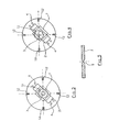
- the pressure force measuring device designated in its entirety by the reference numeral 1 has a pressure / voltage converter 2 in chip technology, which has a spherical cap-shaped sensor surface 3. A force acting on this sensor surface 3 mechanical pressure force F is converted by the pressure / voltage converter into an electrical output signal which is proportional to the force acting on the sensor surface force F, said electrical signal via electrical Connections 4 is output and transmitted to a display or evaluation device, not shown, via electrical lines, not shown.
- the pressure / voltage converter 2 is arranged between a base plate 5 and a cover plate 6, wherein these two discs 5 and 6 are clamped by a plurality of springs 8 against each other.
- the springs 4 are thus tension springs, by means of which a bias voltage is applied to the sensor surface 3.
- an adjusting disc 7 is arranged, which has a spherical cap-shaped recess 9, which is adapted to the spherical cap-shaped sensor surface 3.
- the adjusting disk 7 is arranged so that the sensor surface 3 engages in the recess 9. Due to the spherical cap shape of the sensor surface 3 and the recess 9, the cover plate 6 can thus be tilted or oscillate relative to the pressure / voltage converter 2 and relative to the base plate 5, as in FIG Fig. 2 shown.
- the possible tilt angle ⁇ is limited by the geometry of the sensor surface and the adjusting disk, in that one edge of the adjusting disk 7 comes to rest on an upper side of the pressure / voltage converter 2 or the base disk 5.
- the adjusting disk has a thickness of 0.5 mm and a longitudinal extent of 7.0 mm.
- the cover disc and the base disc each have a thickness of 0.8mm.
- the entire height of the bottom of the base disk up to the top of the cover disc is 5.68mm. This can be about tilt angle of 20 ° realize, which is sufficient for the application areas mentioned in medical technology. By appropriate dimensioning of the individual elements, however, it is also possible to realize larger tilt angles.
- the base plate 5 has an approximately central opening 10 and the cover plate 6 has an approximately central opening 11, wherein the diameter of the opening 11 is smaller than the adjusting disc 7, so that the adjusting disc 7 always with the the pressure / voltage converter 2 facing bottom of the cover plate is in contact.
- the two openings 10 and 11 therethrough Moving and thus adjusting are performed, wherein after complete adjustment of the pressure / - voltage converter 2 is fixedly connected to the base plate 5, for example by gluing and also the adjusting disk 7 with the cover plate. 6
- Fig. 5 shows a section through the adjusting disc 7, in which the spherical cap-shaped recess 9 is clearly visible.
- the adjusting disk 7 may be annular in plan view. But you can also, as in 3 and 4 indicated, rectangular or have any other shape.
- the bias voltage which is exerted on the pressure / voltage converter 2 can be adjusted.
- the position of the pressure / voltage converter is shifted so that after applying each of the same force to all points of the cover plate 6 of the pressure / voltage converter registers the same force.
- Fig. 2 shown causes an off-center on the cover plate 6 acting force F, pivoting or tilting of the cover plate by the tilt angle ⁇ , whereby the in Fig. 2 shown left spring 8 is further tensioned and thus exerts a greater force, while the in Fig. 2 shown right spring 8 is compressed and thus relieved.
- the lever arm between the point of force application and the center of rotation is of different lengths and accordingly also those of the respective ones Springs applied forces vary in size, so that the cover plate is always perpendicular to the external force and transmits the pressure of the external force exactly in the direction of the center of the spherical cap-shaped sensor surface 3.
- the bias caused by the springs 8 on the pressure / voltage converter is metrologically permanently registered and represents a significant system advantage. That is, if exceeding the allowable tilt angle ⁇ , for example, characterized in that the cover plate 6 except for the pressure / voltage converter. 2 or the base disk 5 is "levered", the measured force decreases below the value of the preload. As a result, erroneous measurement conditions can already be detected during the data acquisition and can be eliminated early during a running measurement or the measurement can be aborted and repeated.
Landscapes
- Physics & Mathematics (AREA)
- General Physics & Mathematics (AREA)
- Force Measurement Appropriate To Specific Purposes (AREA)
- Measuring Fluid Pressure (AREA)
Applications Claiming Priority (1)
| Application Number | Priority Date | Filing Date | Title |
|---|---|---|---|
| DE102010005792A DE102010005792B3 (de) | 2010-01-25 | 2010-01-25 | Druckkraftmesseinrichtung |
Publications (2)
| Publication Number | Publication Date |
|---|---|
| EP2348295A2 true EP2348295A2 (fr) | 2011-07-27 |
| EP2348295A3 EP2348295A3 (fr) | 2014-07-30 |
Family
ID=43980343
Family Applications (1)
| Application Number | Title | Priority Date | Filing Date |
|---|---|---|---|
| EP11000108.8A Withdrawn EP2348295A3 (fr) | 2010-01-25 | 2011-01-08 | Dispositif de mesure de la force de pression |
Country Status (3)
| Country | Link |
|---|---|
| US (1) | US8448531B2 (fr) |
| EP (1) | EP2348295A3 (fr) |
| DE (1) | DE102010005792B3 (fr) |
Families Citing this family (11)
| Publication number | Priority date | Publication date | Assignee | Title |
|---|---|---|---|---|
| DE102011016379B4 (de) | 2011-04-07 | 2013-07-18 | Medi Gmbh & Co. Kg | Vorrichtung zum Trainieren des Aufbringens von Kompressionsmaterial |
| CN103359080B (zh) * | 2013-07-16 | 2015-08-19 | 中联重科股份有限公司 | 支腿垫板、工程机械的倾翻报警装置 |
| CA3020676A1 (fr) | 2016-04-05 | 2017-10-12 | Sfh Oxford Ltd. | Capteur de pression |
| EP4701393A2 (fr) | 2017-02-09 | 2026-02-25 | Nextinput, Inc. | Capteurs de force numériques intégrés et procédés de fabrication associés |
| US11243125B2 (en) | 2017-02-09 | 2022-02-08 | Nextinput, Inc. | Integrated piezoresistive and piezoelectric fusion force sensor |
| US11243126B2 (en) | 2017-07-27 | 2022-02-08 | Nextinput, Inc. | Wafer bonded piezoresistive and piezoelectric force sensor and related methods of manufacture |
| US11579028B2 (en) | 2017-10-17 | 2023-02-14 | Nextinput, Inc. | Temperature coefficient of offset compensation for force sensor and strain gauge |
| WO2019099821A1 (fr) * | 2017-11-16 | 2019-05-23 | Nextinput, Inc. | Atténuateur de force pour capteur de force |
| EP3933365B1 (fr) * | 2020-07-02 | 2023-03-01 | TE Connectivity Solutions GmbH | Ensemble de capteur de force et procédé de mesure d'une force |
| GB2614715B (en) * | 2022-01-12 | 2024-01-31 | Veinsense Ltd | A Sensor |
| JP2023109029A (ja) * | 2022-01-26 | 2023-08-07 | アルプスアルパイン株式会社 | 荷重センサ装置 |
Family Cites Families (13)
| Publication number | Priority date | Publication date | Assignee | Title |
|---|---|---|---|---|
| US3825804A (en) * | 1972-03-03 | 1974-07-23 | Bbc Brown Boveri & Cie | Clamped disc type semiconductor assembly with built-in contact pressure gage |
| US3894595A (en) * | 1974-10-02 | 1975-07-15 | Mangood Corp | Low-profile platform scale |
| US4122337A (en) * | 1976-02-26 | 1978-10-24 | Matsushita Electric Industrial Co., Ltd. | Pressure-electrical signal conversion means |
| US4383584A (en) * | 1980-02-15 | 1983-05-17 | International Road Dynamics Inc. | Sealed load cell construction |
| DE3274013D1 (en) * | 1982-12-03 | 1986-12-04 | Schenck Ag Carl | Force transferring element for use with a load cell |
| US4712627A (en) * | 1984-08-17 | 1987-12-15 | Measuretek, Inc. | Calibration of weight scale utilizing a capacitative load cell |
| US5900592A (en) * | 1997-08-29 | 1999-05-04 | Lockheed Martin Energy Research Corp. | Load sensing system |
| JP4194165B2 (ja) * | 1998-04-10 | 2008-12-10 | 富士通コンポーネント株式会社 | ポインティングデバイス |
| JP3479064B1 (ja) * | 2002-04-12 | 2003-12-15 | 北陸電気工業株式会社 | 半導体力センサ |
| DE102004038421A1 (de) * | 2004-07-30 | 2006-03-23 | Paul Hartmann Ag | Vorrichtung zum Bestimmen von Parametern von insbesondere therapeutischen Kompressionsmaßnahmen an Gliedmaßen |
| WO2006030405A1 (fr) * | 2004-09-14 | 2006-03-23 | University Of Limerick | Dispositif a transducteur pour mesurer des pressions biomedicales |
| DE102005020176A1 (de) * | 2005-04-28 | 2006-11-16 | Robert Bosch Gmbh | Mikromechanischer Drucksensor sowie ein entsprechendes Herstellungsverfahren |
| US7504594B1 (en) * | 2007-10-05 | 2009-03-17 | Nucor Corporation | Steel coil weighing apparatus and method for use thereof |
-
2010
- 2010-01-25 DE DE102010005792A patent/DE102010005792B3/de not_active Expired - Fee Related
-
2011
- 2011-01-08 EP EP11000108.8A patent/EP2348295A3/fr not_active Withdrawn
- 2011-01-25 US US13/012,871 patent/US8448531B2/en not_active Expired - Fee Related
Non-Patent Citations (1)
| Title |
|---|
| None |
Also Published As
| Publication number | Publication date |
|---|---|
| US20110179886A1 (en) | 2011-07-28 |
| DE102010005792B3 (de) | 2011-06-16 |
| EP2348295A3 (fr) | 2014-07-30 |
| US8448531B2 (en) | 2013-05-28 |
Similar Documents
| Publication | Publication Date | Title |
|---|---|---|
| DE102010005792B3 (de) | Druckkraftmesseinrichtung | |
| EP2779966B1 (fr) | Support de tête anti-ronflement | |
| EP2251660B1 (fr) | Double capteur de température | |
| DE68927397T2 (de) | Sensor und umwandlervorrichtung | |
| EP1093755B1 (fr) | Dispositif de mesure de paramètres d'une personne couchée | |
| DE19840800C1 (de) | Kraftmeßgerät zur Messung der Kraftfähigkeit einzelner Muskelgruppen eines Menschen | |
| WO2010105601A2 (fr) | Moyen auxiliaire pour le revêtement inférieur de plaques magnétiques | |
| DE2558058C3 (de) | Ablaßventil für Blutdruckmeßgeräte u.dgl | |
| EP3863570A1 (fr) | Volume englobant et procédé de détection d'un contour d'un moignon d'amputation | |
| EP1537393A1 (fr) | Dispositif d'indication de forces de traction | |
| DE3610897C2 (fr) | ||
| DE3732891A1 (de) | Schuh mit einer messvorrichtung | |
| DE202008017134U1 (de) | Kompressionsapparat für die Leistenarterie | |
| WO2005011511A1 (fr) | Capteur de force pour un dispositif oblong | |
| AT507198B1 (de) | Kraftmessring mit einem ringförmigen gehäuse | |
| DE102019123701B4 (de) | Vorrichtung und Verfahren zur Erfassung und Modifikation von Normal- und/oder Scherkräften, sowie deren Verwendung | |
| EP0011866A1 (fr) | Dispositif pour l'enregistrement des fonctions corporelles de malades, notamment de nourrissons | |
| EP4387702A1 (fr) | Dispositif à micro-aiguilles et procédé de détection d'au moins une force agissant sur un réseau de micro-aiguilles | |
| DE10102492A1 (de) | Messvorrichtung | |
| DE10038446A1 (de) | Einrichtung zur Überwachung von Fehlbelastungen am Fuss | |
| DE10001698A1 (de) | Vorrichtung und Verfahren zum Messen von Werten einer liegenden Person sowie Drucksensor | |
| DE4418775A1 (de) | Vorrichtung zum Erfassen von Druckbelastungen an Bereichen des menschlichen Körpers, insbesondere an der Fußsohle, mit einer Druckmeßdose | |
| EP0495461A1 (fr) | Dispositif de mesure de la force d'une main ou d'un doigt | |
| DE1766061C3 (de) | Plethysmograph | |
| DE9418055U1 (de) | Vorrichtung zum Erfassen von Druckbelastungen an Bereichen des menschlichen Körpers, insbesondere an der Fußsohle, mit einer Druckmeßdose |
Legal Events
| Date | Code | Title | Description |
|---|---|---|---|
| PUAI | Public reference made under article 153(3) epc to a published international application that has entered the european phase |
Free format text: ORIGINAL CODE: 0009012 |
|
| AK | Designated contracting states |
Kind code of ref document: A2 Designated state(s): AL AT BE BG CH CY CZ DE DK EE ES FI FR GB GR HR HU IE IS IT LI LT LU LV MC MK MT NL NO PL PT RO RS SE SI SK SM TR |
|
| AX | Request for extension of the european patent |
Extension state: BA ME |
|
| RAP1 | Party data changed (applicant data changed or rights of an application transferred) |
Owner name: MEDI GMBH & CO. KG |
|
| PUAL | Search report despatched |
Free format text: ORIGINAL CODE: 0009013 |
|
| AK | Designated contracting states |
Kind code of ref document: A3 Designated state(s): AL AT BE BG CH CY CZ DE DK EE ES FI FR GB GR HR HU IE IS IT LI LT LU LV MC MK MT NL NO PL PT RO RS SE SI SK SM TR |
|
| AX | Request for extension of the european patent |
Extension state: BA ME |
|
| RIC1 | Information provided on ipc code assigned before grant |
Ipc: G01G 23/00 20060101ALI20140624BHEP Ipc: G01L 1/26 20060101AFI20140624BHEP |
|
| STAA | Information on the status of an ep patent application or granted ep patent |
Free format text: STATUS: THE APPLICATION IS DEEMED TO BE WITHDRAWN |
|
| 18D | Application deemed to be withdrawn |
Effective date: 20150131 |