EP2348341A1 - Lichtquellenvorrichtung - Google Patents
Lichtquellenvorrichtung Download PDFInfo
- Publication number
- EP2348341A1 EP2348341A1 EP11000280A EP11000280A EP2348341A1 EP 2348341 A1 EP2348341 A1 EP 2348341A1 EP 11000280 A EP11000280 A EP 11000280A EP 11000280 A EP11000280 A EP 11000280A EP 2348341 A1 EP2348341 A1 EP 2348341A1
- Authority
- EP
- European Patent Office
- Prior art keywords
- light
- light emitting
- emitting unit
- source apparatus
- light source
- Prior art date
- Legal status (The legal status is an assumption and is not a legal conclusion. Google has not performed a legal analysis and makes no representation as to the accuracy of the status listed.)
- Withdrawn
Links
- 230000008901 benefit Effects 0.000 description 8
- 230000003287 optical effect Effects 0.000 description 4
- 239000012788 optical film Substances 0.000 description 4
- 238000010586 diagram Methods 0.000 description 2
- 238000005286 illumination Methods 0.000 description 2
- 238000009434 installation Methods 0.000 description 2
- 238000012986 modification Methods 0.000 description 2
- 230000004048 modification Effects 0.000 description 2
- 238000000576 coating method Methods 0.000 description 1
- 230000008878 coupling Effects 0.000 description 1
- 238000010168 coupling process Methods 0.000 description 1
- 238000005859 coupling reaction Methods 0.000 description 1
- 238000005516 engineering process Methods 0.000 description 1
- 230000004313 glare Effects 0.000 description 1
- 239000000463 material Substances 0.000 description 1
- 238000000034 method Methods 0.000 description 1
Images


Classifications
-
- G—PHYSICS
- G02—OPTICS
- G02B—OPTICAL ELEMENTS, SYSTEMS OR APPARATUS
- G02B6/00—Light guides; Structural details of arrangements comprising light guides and other optical elements, e.g. couplings
- G02B6/0001—Light guides; Structural details of arrangements comprising light guides and other optical elements, e.g. couplings specially adapted for lighting devices or systems
- G02B6/0011—Light guides; Structural details of arrangements comprising light guides and other optical elements, e.g. couplings specially adapted for lighting devices or systems the light guides being planar or of plate-like form
- G02B6/0066—Light guides; Structural details of arrangements comprising light guides and other optical elements, e.g. couplings specially adapted for lighting devices or systems the light guides being planar or of plate-like form characterised by the light source being coupled to the light guide
- G02B6/0068—Arrangements of plural sources, e.g. multi-colour light sources
-
- G—PHYSICS
- G02—OPTICS
- G02B—OPTICAL ELEMENTS, SYSTEMS OR APPARATUS
- G02B6/00—Light guides; Structural details of arrangements comprising light guides and other optical elements, e.g. couplings
- G02B6/0001—Light guides; Structural details of arrangements comprising light guides and other optical elements, e.g. couplings specially adapted for lighting devices or systems
- G02B6/0011—Light guides; Structural details of arrangements comprising light guides and other optical elements, e.g. couplings specially adapted for lighting devices or systems the light guides being planar or of plate-like form
- G02B6/0033—Means for improving the coupling-out of light from the light guide
- G02B6/0035—Means for improving the coupling-out of light from the light guide provided on the surface of the light guide or in the bulk of it
- G02B6/004—Scattering dots or dot-like elements, e.g. microbeads, scattering particles, nanoparticles
- G02B6/0043—Scattering dots or dot-like elements, e.g. microbeads, scattering particles, nanoparticles provided on the surface of the light guide
-
- G—PHYSICS
- G02—OPTICS
- G02B—OPTICAL ELEMENTS, SYSTEMS OR APPARATUS
- G02B6/00—Light guides; Structural details of arrangements comprising light guides and other optical elements, e.g. couplings
- G02B6/0001—Light guides; Structural details of arrangements comprising light guides and other optical elements, e.g. couplings specially adapted for lighting devices or systems
- G02B6/0011—Light guides; Structural details of arrangements comprising light guides and other optical elements, e.g. couplings specially adapted for lighting devices or systems the light guides being planar or of plate-like form
- G02B6/0033—Means for improving the coupling-out of light from the light guide
- G02B6/005—Means for improving the coupling-out of light from the light guide provided by one optical element, or plurality thereof, placed on the light output side of the light guide
- G02B6/0055—Reflecting element, sheet or layer
-
- G—PHYSICS
- G02—OPTICS
- G02B—OPTICAL ELEMENTS, SYSTEMS OR APPARATUS
- G02B6/00—Light guides; Structural details of arrangements comprising light guides and other optical elements, e.g. couplings
- G02B6/0001—Light guides; Structural details of arrangements comprising light guides and other optical elements, e.g. couplings specially adapted for lighting devices or systems
- G02B6/0011—Light guides; Structural details of arrangements comprising light guides and other optical elements, e.g. couplings specially adapted for lighting devices or systems the light guides being planar or of plate-like form
- G02B6/0033—Means for improving the coupling-out of light from the light guide
- G02B6/0058—Means for improving the coupling-out of light from the light guide varying in density, size, shape or depth along the light guide
- G02B6/0061—Means for improving the coupling-out of light from the light guide varying in density, size, shape or depth along the light guide to provide homogeneous light output intensity
Definitions
- the invention relates to a light source apparatus, and more particularly, to a light source apparatus having a light guide plate.
- LED light sources adopted by illumination devices have gradually changed from incandescent lamps and fluorescent lamps to fast-developing light emitting diodes (LEDs).
- LED has such advantages as low power consumption, long lifespan, environment friendliness, fast start-up, and small volume, etc.
- the power of LED has been increasing along with the advancement of LED techniques.
- LED is one of the main promising candidates to replace conventional fluorescent lamps in residential and industrial applications.
- LED is a kind of spot light source, the light emitted by a LED is focused and therefore may cause glare to human eyes.
- a side incident type light source apparatus with a flat light guide plate is developed.
- LEDs are disposed at a side of the flat light guide plate, and the flat light guide plate guides the light emitted by the LEDs to the front of the flat light guide plate to produce a uniform surface light source.
- FIGs. 5-7 A lighting installation based on a light guide is illustrated in FIGs. 5-7 in U.S. Patent No. 4105293 .
- the lighting installation includes a light guide plate having a round light emitting surface and a plurality of light sources surrounding the light guide plate.
- a backlight module is disclosed in FIG. 1 in U.S. Patent No. 7063450 , wherein a special light diffusing structure is formed at the light incident side of the light guide plate such that the light incident angle is enlarged and accordingly the light uniformity is increased.
- a round or oval LED backlight source is disclosed in http://tw.ttnet.net/cshow html.jsp/%6c%65%64%b6%ea%ab%ac%be%f2%b6%ea%ab%ac %ad%49%a5%fa%aa%4f/SS/cooklang/1/prdhtm/Y/cono/40002148/item no/14/itno/LG120/ dtno/010/type1/A, wherein the light guide plate is in a round or oval shape, and the light source emits light toward the center of the light guide plate.
- the invention is directed to a light source apparatus with high light uniformity and light emitting efficiency.
- a light source apparatus including a light guide plate, a first light emitting unit, and a second light emitting unit.
- the light guide plate has a first surface, a second surface opposite to the first surface, a first side surface, and a second side surface opposite to the first side surface.
- the first light emitting unit is disposed beside the first side surface and capable of providing a first light beam, wherein the first light beam is capable of entering the light guide plate through the first side surface.
- the second light emitting unit is disposed beside the second side surface and capable of providing a second light beam, wherein the second light beam is capable of entering the light guide plate through the second side surface.
- the first light emitting unit has a central line passing through a geometric center of the first light emitting unit and being perpendicular to the first side surface.
- the second light emitting unit has a central line passing through a geometric center of the second light emitting unit and being perpendicular to the second side surface, and the central line of the first light emitting unit does not coincide with the central line of the second light emitting unit.
- the first side surface is substantially parallel to the second side surface.
- the first side surface has a first mid-perpendicular
- the second side surface has a second mid-perpendicular, wherein the first mid-perpendicular and the second mid-perpendicular do not coincide with each other.
- the central line of the first light emitting unit is substantially parallel to the central line of the second light emitting unit.
- a light source apparatus including a light guide plate, a first light emitting unit, and a second light emitting unit.
- the light guide plate has a first surface, a second surface opposite to the first surface, a first side surface, and a second side surface opposite to the first side surface.
- the first light emitting unit is disposed beside the first side surface and capable of providing a first light beam, wherein the first light beam is capable of entering the light guide plate through the first side surface.
- the second light emitting unit is disposed beside the second side surface and capable of providing a second light beam, wherein the second light beam is capable of entering the light guide plate through the second side surface.
- the first side surface has a first mid-perpendicular
- the second side surface has a second mid-perpendicular, wherein the first mid-perpendicular and the second mid-perpendicular do not coincide with each other.
- the first side surface is substantially parallel to the second side surface.
- a width of the first side surface in the direction parallel to the first surface is defined as A
- a width of the first light emitting unit in the direction parallel to the first surface is defined as B
- B/A is greater than or equal to 45% and smaller than or equal to 60%.
- a width of the first side surface in the direction parallel to the first surface is defined as A
- a perpendicular distance between the first side surface and the second side surface is defined as C
- A/C is greater than or equal to 50% and smaller than or equal to 75%.
- a width of the first side surface in the direction parallel to the first surface is defined as A
- a width of the overlap between the orthographic projection of the second side surface on the first side surface and the first side surface in the direction parallel to the first surface is defined as D
- D/A is greater than or equal to 65% and smaller than or equal to 90%.
- the light source apparatus further includes a plurality of scattering microstructures disposed on at least one of the first surface and the second surface.
- the number density of the scattering microstructures gradually increases from two ends of the light guide plate close to the first side surface and the second side surface toward the central portion of the light guide plate away from the first side surface and the second side surface.
- the light source apparatus further includes a reflection unit disposed on the second surface.
- the light source apparatus further includes two reflection units respectively disposed on a portion of the first side surface and a portion of the second side surface, and the two reflection units are respectively disposed beside the first light emitting unit and the second light emitting unit.
- the light source apparatus further includes a third side surface and a fourth side surface opposite to the third side surface.
- the third side surface connects the first side surface and the second side surface
- the fourth side surface connects the first side surface and the second side surface, wherein each of the third side surface and the fourth side surface is a curved surface.
- the embodiment or the embodiments of the invention may have at least one of the following advantages.
- a light guide plate is adopted for guiding the light
- the first light emitting unit and the second light emitting unit are respectively disposed at sides of the light guide plate, wherein the central line of the first light emitting unit and the central line of the second light emitting unit do not coincide with each other so that the first light emitting unit and the second light emitting unit do not face each other directly, and accordingly the light uniformity and light emitting efficiency of the light source apparatus are improved.
- the first mid-perpendicular of the first side surface and the second mid-perpendicular of the second side surface do not coincide with each other, so that the light uniformity and light emitting efficiency of the light source apparatus are further improved.
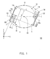
- FIG. 1 is a top view of a light source apparatus according to an embodiment of the invention.
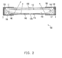
- FIG. 2 is a cross-sectional view of the light source apparatus in FIG. 1 along line I-I.
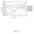
- FIG. 3 is a diagram illustrating the light uniformities presented by the light source apparatus in FIG. 1 when a first side surface and a second side surface of the light source apparatus form different angles with the YZ plane.
- FIG. 4 is a top view of a light source apparatus with a first side surface and a second side surface parallel to the YZ plane.
- FIG. 5 is a graph illustrating the light emitting efficiency presented by a light source apparatus when a first side surface and a second side surface in the light source apparatus form different angels with the YZ plane.
- the light source apparatus 100 includes a light guide plate 110, a first light emitting unit 120, and a second light emitting unit 130.
- the light guide plate 110 has a first surface 112, a second surface 114 opposite to the first surface 112, a first side surface 116, and a second side surface 118 opposite to the first side surface 116.
- the first side surface 116 and the second side surface 118 may be two planes parallel to each other.
- the light guide plate 110 may further include a third side surface S3 and a fourth side surface S4 opposite to the third side surface S3, as shown in FIG. 1 .
- the third side surface S3 connects the first side surface 116 and the second side surface 118
- the fourth side surface S4 connects the first side surface 116 and the second side surface 118
- each of the third side surface S3 and the fourth side surface S4 is a curved surface.
- the third side surface S3 and the fourth side surface S4 are respectively a cylindrical curved surface
- the third side surface S3 and the fourth side surface S4 are respectively a elliptical cylindrical curved surface.
- the invention is not limited to foregoing examples, and in an embodiment, the third side surface S3 and the fourth side surface S4 may be different from each other, or the third side surface S3 and the fourth side surface S4 may also be other different curved surfaces.
- the light guide plate 110 is an elliptical cylindrical light guide plate.
- the first side surface 116 and the second side surface 118 (as illustrated in FIG. 1 ) of the light guide plate 110 may be formed by cutting the light guide plate 110 along a shorter "sides" of the ellipse at an angle ⁇ .
- the cutting direction of the first side surface 116 and the second side surface 118 forms the angle ⁇ with the YZ plane, as shown in FIG. 1 .
- the first light emitting unit 120 is disposed beside the first side surface 116 and capable of providing a first light beam L1
- the second light emitting unit 130 is disposed beside the second side surface 118 and capable of providing a second light beam L2, wherein the first light beam L1 enters the light guide plate 110 through the first side surface 116, and the second light beam L2 enters the light guide plate 110 through the second side surface 118, as shown in FIG. 1 and FIG. 2 .
- the first light emitting unit 120 and the second light emitting unit 130 are respectively disposed beside the first side surface 116 and the second side surface 118, the first side surface 116 and the second side surface 118 are light incident surfaces of the light guide plate 110.
- the first light beam L1 and the second light beam L2 transmitted within the light guide plate 110 are transmitted out of the light guide plate 110 through the first surface 112.
- the first surface 112 is the light emitting surface of the light guide plate 110.
- the first light emitting unit 120 and the second light emitting unit 130 are each a light emitting diode (LED) light bar, for example, wherein each LED light bar is composed of a plurality of LEDs disposed on a board.
- the first light emitting unit 120 and the second light emitting unit 130 may also be fluorescent lamps or other suitable light emitting devices.
- the first light emitting unit 120 has a central line 122 passing through a geometric center of the first light emitting unit 120 and being perpendicular to the first side surface118
- the second light emitting unit 130 has a central line 132 passing through a geometric center of the second light emitting unit 130 and being perpendicular to the second side surface 118.
- each of the first side surface 116 and the second side surface 118 respectively forms an angle ⁇ with the YZ plane and the first light emitting unit 120 and the second light emitting unit 130 do not face each other directly, the central line 122 of the first light emitting unit 120 disposed beside the first side surface 116 does not coincide with the central line 132 of the second light emitting unit 130 disposed beside the second side surface 118, as shown in FIG. 1 .
- the central line 122 of the first light emitting unit 120 and the central line 132 of the second light emitting unit 130 are substantially parallel to but do not coincide with each other.
- the light guide plate 110 will be described as an elliptical cylindrical light guide plate. However, the invention is not limited thereto. Because the first side surface 116 and the second side surface 118 are formed by cutting the light guide plate 110 at an angle ⁇ with respect to the YZ plane and are substantially parallel to each other, a first mid-perpendicular 116a of the first side surface 116 does not coincide with a second mid-perpendicular 118a of the second side surface 118. Similarly, because the first side surface 116 and the second side surface 118 are parallel to each other, the first mid-perpendicular 116a of the first side surface 116 and the second mid-perpendicular 118a of the second side surface 118 are substantially parallel to but do not coincide with each other.
- the light guide plate 110 formed with different value of the angle ⁇ causes the light source apparatus 100 to present different optical effect, such as the light uniformity or the light emitting efficiency of the light source apparatus 100. This fact will be described below.
- FIG. 3 is a diagram illustrating the light uniformities presented by the light source apparatus in FIG. 1 when the first side surface 116 and the second side surface 118 in the light source apparatus form different angle ⁇ with the YZ plane, wherein different curves present different light emitting range, and the value of the angle ⁇ is respectively assumed to be 5°, 10°, 15°, and 20°.
- a visible region T1 is first defined with a center point C0 of the light guide plate 110 as a center.
- the visible region T1 is in a round shape, as shown in FIG. 1 .
- 8 points C1 with equal distances in between are defined at the edge of the visible region T1.
- the first light emitting unit 120 and the second light emitting unit 130 respectively provide the first light beam L1 and the second light beam L2 entering the light guide plate 110
- the light intensities at the points C0 and C1 within the visible region T1 are respectively measured, and the light uniformity within the visible region T1is defined by dividing the smallest light intensities at the points C0 and C1 by the greatest light intensities at the points C0 and C1.
- the curves 311-314 respectively represent the light uniformity within the visible region T1 having a size of 20mmx20mm, 30mmx30mm, 40mm ⁇ 40mm, and 50mmx50mm on the light guide plate 110.
- the greater the angle ⁇ is i.e., the greater the angle ⁇ of the first side surface 116 and the second side surface 118 with respect to the YZ plane
- the value of the angle ⁇ is not unlimited, and the value of the angle ⁇ should be determined according to the size of the visible region T1.
- the light source apparatus 100 presents a good optical quality (for example, a high light uniformity or light emitting efficiency) when the angle ⁇ is greater than or equal to 15° and smaller than or equal to 20°.
- a width of the first side surface 116 in the direction parallel to the first surface 112 is defined as A.
- a width of the first light emitting unit 120 in the direction parallel to the first surface 112 is defined as B.
- a perpendicular distance between the first side surface 116 and the second side surface 118 is defined as C.
- a width of the overlap between the orthographic projection of the second side surface 118 on the first side surface 116 and the first side surface 116 in the direction parallel to the first surface 112 is defined as D.
- B/A is about greater than or equal to 45% and smaller than or equal to 60% corresponding to the angle ⁇
- A/C is about greater than or equal to 50% and smaller than or equal to 75% corresponding to the angle ⁇
- D/A is about greater than or equal to 65% and smaller than or equal to 90%.
- B/A is about 55.8%
- A/C is about 57%
- D/A is about 70%.
- B/A is about 50.5%
- A/C is about 70.7%
- D/A is about 82%.
- a light source apparatus 200 as illustrated in FIG. 4 is presented when the angle ⁇ is 0°.
- both the first side surface 216 and the second side surface 218 of the light guide plate 210 are parallel to the YZ plane (i.e., the angle ⁇ formed by the first side surface 216 and the second side surface 218 with respect to the YZ plane is 0°).
- the first light emitting unit 220 disposed beside the first side surface 216 and the second light emitting unit 230 disposed beside the second side surface 218 face each other directly.
- the central line 222 of the first light emitting unit 220 and the central line 232 of the second light emitting unit 230 are substantially parallel to and coincide with each other, as shown in FIG. 4 .
- the light uniformity of the light source apparatus 200 having the angle ⁇ as 0° is measured as described above, the light uniformities presented by the light source apparatus 200 with different sizes of the visible region T1 (20mmx20mm, 30mmx30mm, 40mmx40mm, and 50mmx50mm) are very different. Namely, the light uniformity presented by the light source apparatus 200 is not as good as the light uniformity presented by the light source apparatus 100 in the embodiment when the angle ⁇ formed by the first side surface 216 and the second side surface 218 with respect to the YZ plane is 0°.
- the light emitting efficiency of the light source apparatus 100 of the embodiment increases along with the angle ⁇ formed by the first side surface 116 and the second side surface 118 with respect to the YZ plane based on the light emitting efficiency of the light source apparatus 200 in FIG. 4 . It may be understood from FIG. 5 that the light emitting efficiency of the light source apparatus 100 increases along with the angle ⁇ formed by the first side surface 116 and the second side surface 118 with respect to the YZ plane.
- the light source apparatus 100 further includes a plurality of scattering microstructures 140 (as shown in FIG. 2 ).
- the scattering microstructures 140 may be disposed on at least one of the first surface 112 and the second surface 114.
- the scattering microstructures 140 are disposed on the second surface 114.
- the invention is not limited thereto.
- a number density of the scattering microstructures 140 gradually increases from two ends of the light guide plate 110 close to the first side surface 116 and the second side surface 118 toward the central portion of the light guide plate 110 away from the first side surface 116 and the second side surface 118, as shown in FIG. 2 .
- the scattering microstructures 140 may be disposed for destroying the total internal reflection of the first light beam L 1 and the second light beam L2 within the light guide plate 110.
- a reflection unit 170 may be disposed at one side of the second surface 114 such that part of the first light beam L1 or the second light beam L2 is scattered by the scattering microstructures 140 and accordingly radiated toward the reflection unit 170.
- the reflection unit 170 reflects the first light beam L1 or the second light beam L2 so that the first light beam L1 or the second light beam L2 sequentially passes through the second surface 114 and the first surface 112 and emerges out of the light guide plate 110.
- another part of the first light beam L1 or the second light beam L2 is reflected by the scattering microstructures 140 and accordingly radiated toward the first surface 112 and emerges out of the light guide plate 110 through the first surface 112.
- the scattering microstructures 140 may be bumps. However, in other embodiments, the scattering microstructures 140 may also be scattering materials, pits, raised patterns, or dimpled patterns. In the embodiment, the reflection unit 170 may be a reflector.
- the light source apparatus 100 further includes two reflection units 162 and 164, as shown in FIG. 1 and FIG. 2 .
- the reflection units 162 and 164 are respectively disposed on a portion of the first side surface 116 and a portion of the second side surface 118 and are respectively located beside the first light emitting unit 120 and the second light emitting unit 130.
- the first light beam L1 and the second light beam L2 respectively reach the second side surface 118 and the first side surface 116
- the first light beam L1 and the second light beam L2 are reflected by the reflection units 162 and 164 so that less of the first light beam L1 and the second light beam L2 emerges out of the light guide plate 110 through the first side surface 116 and the second side surface 118 or absorbed by the opposite first light emitting unit 120 and second light emitting unit 130.
- the light source apparatus 100 disposed with the reflection units 162 and 164 has better light utilization efficiency and optical performance.
- the reflection units 162 and 164 may be reflective sheets or coatings.
- an optical film 150 may be further disposed on the first surface 112, as shown in FIG. 2 .
- the optical film 150 may be an optical diffuser.
- the light source apparatus 100 may further include a top cover 180.
- the top cover 180 is capable of fixing the light guide plate 110, the first light emitting unit 120, the second light emitting unit 130, the reflection unit 170, and the optical film 150 and exposing the visible region T1.
- the light guide plate 110 in the embodiment adopts such a design as illustrated in FIG. 1 , it may be observed from the curve in FIG. 3 corresponding to the size of the visible region T1 as 50mmx50mm that the light source apparatus 100 still has a good light uniformity even when the visible region T1 has a large size and the angle ⁇ falls between 15° and 20°.
- the light source apparatus 100 offers a high light uniformity when the visible region T1 becomes larger. Thereby, the light emitting surface and light utilization efficiency of the light source apparatus 100 are both increased.
- the embodiment or the embodiments of the invention may have at least one of the following advantages.
- the light source apparatus adopts a light guide plate for guiding the light, and the first light emitting unit and the second light emitting unit are respectively disposed at sides of the light guide plate, wherein the central line of the first light emitting unit and the central line of the second light emitting unit do not coincide with each other so that the first light emitting unit and the second light emitting unit do not face each other directly, and accordingly the light uniformity and light emitting efficiency of the light source apparatus are improved.
- the first mid-perpendicular of the first side surface and the second mid-perpendicular of the second side surface do not coincide with each other so that the light uniformity and light emitting efficiency of the light source apparatus are further improved.
- the brightness and uniformity of the light emitting surface are well controlled. Furthermore, in embodiments of the invention, because the scattering microstructures are disposed in the light source apparatus, the light emitting efficiency of the light source apparatus is further improved.
- the term "the invention”, “the present invention” or the like does not necessarily limit the claim scope to a specific embodiment, and the reference to particularly preferred exemplary embodiments of the invention does not imply a limitation on the invention, and no such limitation is to be inferred.
- the invention is limited only by the spirit and scope of the appended claims.
- the abstract of the disclosure is provided to comply with the rules requiring an abstract, which will allow a searcher to quickly ascertain the subject matter of the technical disclosure of any patent issued from this disclosure. It is submitted with the understanding that it will not be used to interpret or limit the scope or meaning of the claims. Any advantages and benefits described may not apply to all embodiments of the invention.
Landscapes
- Physics & Mathematics (AREA)
- General Physics & Mathematics (AREA)
- Optics & Photonics (AREA)
- Planar Illumination Modules (AREA)
Applications Claiming Priority (1)
| Application Number | Priority Date | Filing Date | Title |
|---|---|---|---|
| TW099101108A TWI386591B (zh) | 2010-01-15 | 2010-01-15 | 光源裝置 |
Publications (1)
| Publication Number | Publication Date |
|---|---|
| EP2348341A1 true EP2348341A1 (de) | 2011-07-27 |
Family
ID=43920046
Family Applications (1)
| Application Number | Title | Priority Date | Filing Date |
|---|---|---|---|
| EP11000280A Withdrawn EP2348341A1 (de) | 2010-01-15 | 2011-01-14 | Lichtquellenvorrichtung |
Country Status (4)
| Country | Link |
|---|---|
| US (1) | US8414175B2 (de) |
| EP (1) | EP2348341A1 (de) |
| JP (1) | JP2011146369A (de) |
| TW (1) | TWI386591B (de) |
Cited By (1)
| Publication number | Priority date | Publication date | Assignee | Title |
|---|---|---|---|---|
| WO2021051753A1 (zh) * | 2019-09-16 | 2021-03-25 | 神盾股份有限公司 | 具有屏下式红外线生物感测器的电子设备 |
Families Citing this family (8)
| Publication number | Priority date | Publication date | Assignee | Title |
|---|---|---|---|---|
| US20130027971A1 (en) * | 2011-07-29 | 2013-01-31 | Enlight Corporation | Dazzle prevention lighting fixture with light guide means to disperse emitted light uniformly |
| JP2017062869A (ja) * | 2014-01-30 | 2017-03-30 | シチズン時計株式会社 | 面状ライトユニット |
| TWI507746B (zh) * | 2014-02-07 | 2015-11-11 | E Ink Holdings Inc | 導光模組 |
| CN103969736B (zh) * | 2014-04-24 | 2016-05-18 | 京东方科技集团股份有限公司 | 一种导光结构和显示装置 |
| TWI579494B (zh) * | 2015-04-13 | 2017-04-21 | 茂林光電科技股份有限公司 | 發光框架 |
| WO2017047488A1 (ja) * | 2015-09-15 | 2017-03-23 | シャープ株式会社 | 照明装置及び表示装置 |
| JP6540486B2 (ja) * | 2015-12-08 | 2019-07-10 | 豊田合成株式会社 | 発光装置 |
| JP7746009B2 (ja) | 2017-08-01 | 2025-09-30 | テクニカル コンシューマー プロダクツ インコーポレイテッド | 二次的サービスのための能力を有するエッジ照明型照明器具 |
Citations (9)
| Publication number | Priority date | Publication date | Assignee | Title |
|---|---|---|---|---|
| US4105293A (en) | 1976-08-25 | 1978-08-08 | Aizenberg Julian Borisovich | Lighting installation based on light guide |
| US20020093808A1 (en) * | 2001-01-17 | 2002-07-18 | Minebea Co. , Ltd. | Spread illuminating apparatus |
| US7063450B2 (en) | 1999-05-11 | 2006-06-20 | Nichia Corporation | Surface light emitting device |
| US20060181902A1 (en) * | 2004-12-27 | 2006-08-17 | Nichia Corporation | Optical guide and surface light emitting apparatus using the same |
| DE102006056150A1 (de) * | 2006-11-28 | 2008-05-29 | Patent-Treuhand-Gesellschaft für elektrische Glühlampen mbH | Vorrichtung zur Abstrahlung elektromagnetischer Strahlung und Anzeigevorrichtung |
| EP1992869A2 (de) * | 2007-05-16 | 2008-11-19 | Rohm and Haas Denmark Finance A/S | Lichtleiter für LCD-Anzeigen |
| US20090040787A1 (en) * | 2007-08-09 | 2009-02-12 | Takayuki Nagata | Planar illumination device and liquid crystal display device using the same |
| EP2042899A1 (de) * | 2007-09-28 | 2009-04-01 | Fujifilm Corporation | Planare Beleuchtungsvorrichtung |
| US20090109373A1 (en) * | 2007-10-24 | 2009-04-30 | Hitoshi Taniguchi | Liquid Crystal Display |
Family Cites Families (11)
| Publication number | Priority date | Publication date | Assignee | Title |
|---|---|---|---|---|
| JP2628636B2 (ja) * | 1986-03-31 | 1997-07-09 | 工業技術院長 | 面状光源 |
| JP2813942B2 (ja) | 1993-05-11 | 1998-10-22 | 本田技研工業株式会社 | 摺動面構成体 |
| JP2001141527A (ja) | 1999-11-16 | 2001-05-25 | Toyoda Gosei Co Ltd | 車両用メータの文字盤照明装置 |
| JP2002203413A (ja) | 2000-12-28 | 2002-07-19 | Mitsubishi Rayon Co Ltd | 面光源装置 |
| JP2004253318A (ja) | 2003-02-21 | 2004-09-09 | Minebea Co Ltd | 面状照明装置 |
| JP4222088B2 (ja) | 2003-04-14 | 2009-02-12 | パナソニック株式会社 | 面発光装置 |
| CN100419522C (zh) * | 2005-08-19 | 2008-09-17 | 鸿富锦精密工业(深圳)有限公司 | 导光板和背光系统 |
| US7780330B2 (en) * | 2007-05-16 | 2010-08-24 | Rohm And Haas Electronics Materials Llc | Elongated illuminators configuration for LCD displays |
| JP2009076349A (ja) | 2007-09-21 | 2009-04-09 | Epson Imaging Devices Corp | 照明装置、電気光学装置、及び電子機器 |
| JP2009205940A (ja) * | 2008-02-28 | 2009-09-10 | Panasonic Corp | 導光シート及びこれを用いた可動接点体 |
| TWM354133U (en) * | 2008-06-27 | 2009-04-01 | Min Chih Technology Co Ltd | Advertisement billboard structure |
-
2010
- 2010-01-15 TW TW099101108A patent/TWI386591B/zh not_active IP Right Cessation
- 2010-11-02 US US12/917,487 patent/US8414175B2/en not_active Expired - Fee Related
- 2010-11-26 JP JP2010264061A patent/JP2011146369A/ja active Pending
-
2011
- 2011-01-14 EP EP11000280A patent/EP2348341A1/de not_active Withdrawn
Patent Citations (9)
| Publication number | Priority date | Publication date | Assignee | Title |
|---|---|---|---|---|
| US4105293A (en) | 1976-08-25 | 1978-08-08 | Aizenberg Julian Borisovich | Lighting installation based on light guide |
| US7063450B2 (en) | 1999-05-11 | 2006-06-20 | Nichia Corporation | Surface light emitting device |
| US20020093808A1 (en) * | 2001-01-17 | 2002-07-18 | Minebea Co. , Ltd. | Spread illuminating apparatus |
| US20060181902A1 (en) * | 2004-12-27 | 2006-08-17 | Nichia Corporation | Optical guide and surface light emitting apparatus using the same |
| DE102006056150A1 (de) * | 2006-11-28 | 2008-05-29 | Patent-Treuhand-Gesellschaft für elektrische Glühlampen mbH | Vorrichtung zur Abstrahlung elektromagnetischer Strahlung und Anzeigevorrichtung |
| EP1992869A2 (de) * | 2007-05-16 | 2008-11-19 | Rohm and Haas Denmark Finance A/S | Lichtleiter für LCD-Anzeigen |
| US20090040787A1 (en) * | 2007-08-09 | 2009-02-12 | Takayuki Nagata | Planar illumination device and liquid crystal display device using the same |
| EP2042899A1 (de) * | 2007-09-28 | 2009-04-01 | Fujifilm Corporation | Planare Beleuchtungsvorrichtung |
| US20090109373A1 (en) * | 2007-10-24 | 2009-04-30 | Hitoshi Taniguchi | Liquid Crystal Display |
Cited By (1)
| Publication number | Priority date | Publication date | Assignee | Title |
|---|---|---|---|---|
| WO2021051753A1 (zh) * | 2019-09-16 | 2021-03-25 | 神盾股份有限公司 | 具有屏下式红外线生物感测器的电子设备 |
Also Published As
| Publication number | Publication date |
|---|---|
| US8414175B2 (en) | 2013-04-09 |
| US20110176329A1 (en) | 2011-07-21 |
| JP2011146369A (ja) | 2011-07-28 |
| TWI386591B (zh) | 2013-02-21 |
| TW201124660A (en) | 2011-07-16 |
Similar Documents
| Publication | Publication Date | Title |
|---|---|---|
| US8414175B2 (en) | Light source apparatus with a light guide plate having a lighting units disposed adjacent to two opposing sides offset with each other | |
| TWI471504B (zh) | 平面光源模組 | |
| TWI282445B (en) | Light guide plate and backlight device using the same | |
| US20080285309A1 (en) | Light guide plate and backlight module having the same | |
| CN101329423A (zh) | 导光板及背光模组 | |
| US9482809B2 (en) | Planar light source | |
| US9234641B2 (en) | Optical lens and light source device | |
| CN103629571B (zh) | 照明装置 | |
| CN105026832A (zh) | 具有弯曲棱柱片的发光模块 | |
| US20110096565A1 (en) | Light source apparatus | |
| TW201428392A (zh) | 側光式背光模組 | |
| US20150103522A1 (en) | Light source module | |
| TWM467584U (zh) | 車輛指示燈 | |
| CN100405165C (zh) | 背光系统及其反光罩 | |
| KR20180012338A (ko) | 조명 장치 | |
| EP2653777A1 (de) | Beleuchtungsvorrichtung und Voutenbeleuchtungsmodul damit | |
| JP5588217B2 (ja) | 照明装置 | |
| JP2010177196A (ja) | 照明装置 | |
| TWI494525B (zh) | 平面燈具 | |
| JP5060910B2 (ja) | 面光源 | |
| EP2315060A2 (de) | Lichtquellenmodul und Lichtquellenvorrichtung | |
| CN103591551B (zh) | 导光装置及照明设备 | |
| KR20120128484A (ko) | 면조명 장치 | |
| CN104930396A (zh) | 侧光式发光模组结构 | |
| TWI522695B (zh) | Side light type light emitting module structure |
Legal Events
| Date | Code | Title | Description |
|---|---|---|---|
| PUAI | Public reference made under article 153(3) epc to a published international application that has entered the european phase |
Free format text: ORIGINAL CODE: 0009012 |
|
| AK | Designated contracting states |
Kind code of ref document: A1 Designated state(s): AL AT BE BG CH CY CZ DE DK EE ES FI FR GB GR HR HU IE IS IT LI LT LU LV MC MK MT NL NO PL PT RO RS SE SI SK SM TR |
|
| AX | Request for extension of the european patent |
Extension state: BA ME |
|
| 17P | Request for examination filed |
Effective date: 20120116 |
|
| 17Q | First examination report despatched |
Effective date: 20121024 |
|
| STAA | Information on the status of an ep patent application or granted ep patent |
Free format text: STATUS: THE APPLICATION IS DEEMED TO BE WITHDRAWN |
|
| 18D | Application deemed to be withdrawn |
Effective date: 20140801 |