EP2348523B1 - Interrupteur à clé antidéflagrant - Google Patents
Interrupteur à clé antidéflagrant Download PDFInfo
- Publication number
- EP2348523B1 EP2348523B1 EP10826012.6A EP10826012A EP2348523B1 EP 2348523 B1 EP2348523 B1 EP 2348523B1 EP 10826012 A EP10826012 A EP 10826012A EP 2348523 B1 EP2348523 B1 EP 2348523B1
- Authority
- EP
- European Patent Office
- Prior art keywords
- rotating shaft
- switch
- explosion
- switch seat
- annular disc
- Prior art date
- Legal status (The legal status is an assumption and is not a legal conclusion. Google has not performed a legal analysis and makes no representation as to the accuracy of the status listed.)
- Active
Links
Images
Classifications
-
- H—ELECTRICITY
- H01—ELECTRIC ELEMENTS
- H01H—ELECTRIC SWITCHES; RELAYS; SELECTORS; EMERGENCY PROTECTIVE DEVICES
- H01H27/00—Switches operated by a removable member, e.g. key, plug or plate; Switches operated by setting members according to a single predetermined combination out of several possible settings
- H01H27/06—Key inserted and then turned to effect operation of the switch
-
- H—ELECTRICITY
- H01—ELECTRIC ELEMENTS
- H01H—ELECTRIC SWITCHES; RELAYS; SELECTORS; EMERGENCY PROTECTIVE DEVICES
- H01H9/00—Details of switching devices, not covered by groups H01H1/00 - H01H7/00
- H01H9/02—Bases, casings, or covers
- H01H9/04—Dustproof, splashproof, drip-proof, waterproof, or flameproof casings
- H01H9/042—Explosion-proof cases
-
- H—ELECTRICITY
- H01—ELECTRIC ELEMENTS
- H01H—ELECTRIC SWITCHES; RELAYS; SELECTORS; EMERGENCY PROTECTIVE DEVICES
- H01H3/00—Mechanisms for operating contacts
- H01H3/32—Driving mechanisms, i.e. for transmitting driving force to the contacts
- H01H3/50—Driving mechanisms, i.e. for transmitting driving force to the contacts with indexing or locating means, e.g. indexing by ball and spring
Definitions
- the present invention relates to an explosion-proof key switch, which is mainly applied to explosion-proof vehicles in various explosive gas environments.
- a key switch is an essential electrical element for starting vehicles.
- conventional key switches cannot be used at all.
- no true explosion-proof key switch is available commercially.
- present key switches for explosion-proof vehicles some key switches are operated by the conventional key switch driving a set of lever mechanism to switch on/off self-made contacts, which have complex structures and are bulky and extremely prone to failure; some key switches need several actions to start vehicles, which is inconvenient for operation.
- the technical problem to be solved by the invention is to provide an explosion-proof key switch with a simple structure, a low cost, a reliable work and a convenient operation.
- the technical solution of the invention is to provide an explosion-proof key switch including a switch seat and a cover plate, wherein a switch lock core and a rotating shaft connected with each other are provided in the switch seat, an output end of the rotating shaft extends through the cover plate to the outside of the switch seat, a microswitch fit with the output end of the rotating shaft is mounted on the cover plate, characterized in that an input end of the rotating shaft is mounted in the switch seat by a copper jacket sleeved on the rotating shaft, both a clearance between the copper jacket and the rotating shaft and a clearance between the copper jacket and the switch seat have a width less than 0.2mm and a length larger than 12.5mm, a notch is provided on an end surface of the output end of the rotating shaft, an rolling wheel being in contact with a longitudinal cutting surface of the notch is provided at one side of a drive end of an elastic rod mounted on the microswitch, and the other side of the drive end of the elastic rod is in contact with a movable contact.
- the middle portion of the rotating shaft is provided with an annular disc which has a diameter larger than the diameter of the rotating shaft and is formed integrally with the rotating shaft.
- the annular disc is embedded in a space between the switch seat and the cover plate. Two recesses are provided on an end surface of the annular disc.
- a blind hole is correspondingly provided in the switch seat, and a spring and a steel ball are placed in the blind hole.
- a positioning pin being axially symmetrical to the blind hole is mounted in the switch seat.
- An elongate groove fit with the positioning pin is provided in the annular disc, and a maximum rotatable angle of the positioning pin within the elongate groove is the same as an angle between the two recesses with respect to an axis of the annular disc.
- the switch lock core and the rotating shaft are connected together by a protrusion-groove structure.
- the input end of the rotating shaft is mounted in the switch seat by the copper jacket sleeved on the rotating shaft, and the clearances between the copper jacket and the rotating shaft, the switch seat have a width less than 0.2mm and a length larger than 12.5mm, so as to effectively prevent explosive flame of explosive gas mixture from extending to the exterior through clearances between components of the switch.
- the present invention adopts the conventional key switch and the microswitch to achieve the explosion-proof function of the system, which has a simple structure, a convenient operation, a low cost and a convenient maintenance.
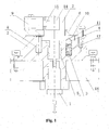
- the embodiment has a switch seat 2 and a cover plate 6.
- a switch lock core 1 and a rotating shaft 7 connected with each other are provided in the switch seat 2.
- the switch lock core 1 and the rotating shaft 7 are connected with each other by a protrusion-groove structure, such that the rotating shaft 7 may be rotated together with the switch lock core 1 under the action of the switch lock core 1.
- the output end of the rotating shaft 7 extends through the cover plate 6 to the outside of the switch seat 2.
- a microswitch 9 fit with the output end of the rotating shaft 7 is mounted on the cover plate 6.
- An input end of the rotating shaft 7 is mounted on the switch seat 2 via a copper jacket 5 sleeved on the rotating shaft 7.
- Both a clearance between the copper jacket 5 and the rotating shaft 7 and a clearance between the copper jacket 5 and the switch seat 2 have a width of 0.1mm and a length of 25mm. Since the clearances are very narrow and their length is relatively long (in comparison with the clearance width of 0.1mm), it is possible to effectively prevent explosive flame from extending to the exterior, so as to achieve the explosion-proof effect.
- a notch 14 is provided on the end surface of the output end of the rotating shaft 7.
- a rolling wheel 15 being in contact with the longitudinal cutting surface of the notch 14 is provided at one side of a drive end of an elastic rod 16 mounted on the microswitch 9, and the other side of the drive end of the elastic rod 16 is in contact with a movable contact 17.
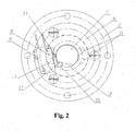
- the middle portion of the rotating shaft 7 is provided with an annular disc 10 which has an diameter larger than the diameter of the rotating shaft 7 and is formed integrally with the rotating shaft 7.
- the annular disc is embedded in the space between the switch seat 2 and the cover plate 6, so that the rotating shaft 7 can rotate only around its axis.
- Two recesses 11 are provided on an end surface of the annular disc.
- a blind hole 12 is provided in the switch seat 2, and a spring 3 and a steel ball 4 are placed in the blind hole 12.
- a positioning pin 8 being axially symmetrical to the blind hole 12 is mounted in the switch seat 2.
- An elongate groove 13 fit with the positioning pin 8 is provided in the annular disc 10.
- the maximum rotatable angle of the positioning pin 8 within the elongate groove 13 is the same as an angle between the two recesses 11 with respect to the axis of the annular disc 10.
- the operation principle of the embodiment is as follows.
- the whole switch is installed in an explosion-proof instrument box 18, wherein the switch seat 2 and the explosion-proof instrument box 18 are connected together by screws and the clearance therebetween has a width of 0.1mm and a length of 25mm, which is the same as the requirement of the clearances between the copper jacket 5 and the rotating shaft 7, the switch seat 2 respectively, so as to achieve the explosion-proof effect.
- the steel ball 4 is located in one of the recesses 11, and the positioning pin 8 abuts against one limit end of the elongate groove.
- the key When being operated, the key is inserted into the switch lock core 1 and then is turned to rotate the rotating shaft 7, so that the rolling wheel 15 moves from the notch 14 onto the outer circumferential surface of the rotating shaft 7 and the elastic rod 16 is deformed to come close to the body of the microswitch 9, so as to push the movable contact 17 to actuate, thereby switching the power on.
- the elongate clearances between the copper jacket 5 and the rotating shaft 7, the switch seat 2, and the elongate clearance between the switch seat 2 and the explosion-proof instrument box 18 are used to achieve the explosion-proof of the system.
- the steel ball 4 comes into the other recess 11, which not only achieves a good hand feeling of a driver at the on/off position but also may hold the switch in the position, and the positioning pin 8 abuts against the other limit ends so as to prevent the excessive operation.
- the switch is required to be turned off, the key is rotated in a reverse direction, so that the rotating shaft 7 is rotated in the reverse direction and the rolling wheel 15 moves from the outer circumferential surface of the rotating shaft 7 to the notch 14.
- the elastic rod 16 is returned under the action of its own elastic force, namely moves far away from the body of the microswitch 9, and the movable contact 17 is simultaneously returned under the action of its own elastic force, so that the power is switched off.
Landscapes
- Rotary Switch, Piano Key Switch, And Lever Switch (AREA)
Claims (4)
- Interrupteur à clé antidéflagrant comprenant un support d'interrupteur (2) et une plaque de protection (6), dans lequel un noyau de ver-rouillage (1) d'interrupteur et un arbre rotatif (7) reliés l'un à l'autre sont disposés dans le support (2) d'interrupteur, une extrémité de sortie de l'arbre rotatif (7) s'étend à travers la plaque de protection (6) jusqu'à l'extérieur du support (2) d'interrupteur, un microinterrup-teur (9) associé à l'extrémité de sortie de l'arbre rotatif (7) est monté sur la plaque de protection (6), caractérisé en ce qu'une extrémité d'entrée de l'arbre rotatif (7) est montée dans le support d'interrupteur (2) par une gaine en cuivre (5) manchonnée sur l'arbre rotatif (7), un espace libre situé entre la gaine en cuivre (5) et l'arbre rotatif (7) et un espace libre situé entre la gaine en cuivre (5) et le support d'interrupteur (2) ont une largeur infé-rieure à 0,2 mm et une longueur supérieure à 12,5 mm, une encoche (14) est prévue sur une surface d'extrémité de l'extrémité de sortie de l'arbre rotatif (7), une roue roulante (15) en contact avec une surface de découpe longitudinale de l'encoche (14) est disposée sur un côté d'une extrémité d'entraînement d'une tige élastique (16) montée sur le microinterrupteur (9), et l'autre côté de l'extrémité d'entraînement de la tige élastique (16) est en contact avec un contact mobile (17).
- Interrupteur à clé antidéflagrant selon la revendication 1, dans lequel la partie inter-médiaire de l'arbre rotatif (7) est pourvue d'un disque annulaire (10) qui a un diamètre supérieur au diamètre de l'arbre rotatif (7) et fait partie intégrante de l'arbre rotatif (7), le disque annulaire est incorporé dans un espace situé entre le support d'interrupteur (2) et la plaque de protection (6), deux renfoncements (11) sont ménagés sur une surface d'extrémité du disque annulaire, un trou borgne (12) est ménagé de façon correspondante dans le support d'interrup-teur (2) et un ressort (3) et une bille en acier (4) sont placés dans le trou borgne.
- Interrupteur à clé antidéflagrant selon la revendication 2, dans lequel une cheville de positionnement (8) étant axialement symétrique au trou borgne (12) est montée dans le support d'interrupteur (2), une rainure allongée (13) associée à la cheville de positionnement (8) est ménagée dans le disque annulaire (10), et un angle de rotation maximum de la cheville de posi-tionnement (8) dans la rainure allongée (13) est le même qu'un angle entre les deux renfoncements (11) par rapport à un axe du disque annulaire (10).
- Interrupteur à clé antidéflagrant selon la revendication 1, 2 ou 3, dans lequel le noyau de verrouillage (1) d'interrupteur et l'arbre rota-tif (7) sont reliés l'un à l'autre par une struc-ture saillie-rainure.
Applications Claiming Priority (2)
| Application Number | Priority Date | Filing Date | Title |
|---|---|---|---|
| CN2009202688735U CN201608087U (zh) | 2009-10-28 | 2009-10-28 | 防爆钥匙开关 |
| PCT/CN2010/075971 WO2011050649A1 (fr) | 2009-10-28 | 2010-08-13 | Interrupteur à clé antidéflagrant |
Publications (3)
| Publication Number | Publication Date |
|---|---|
| EP2348523A1 EP2348523A1 (fr) | 2011-07-27 |
| EP2348523A4 EP2348523A4 (fr) | 2013-12-04 |
| EP2348523B1 true EP2348523B1 (fr) | 2014-07-30 |
Family
ID=42952791
Family Applications (1)
| Application Number | Title | Priority Date | Filing Date |
|---|---|---|---|
| EP10826012.6A Active EP2348523B1 (fr) | 2009-10-28 | 2010-08-13 | Interrupteur à clé antidéflagrant |
Country Status (3)
| Country | Link |
|---|---|
| EP (1) | EP2348523B1 (fr) |
| CN (1) | CN201608087U (fr) |
| WO (1) | WO2011050649A1 (fr) |
Families Citing this family (4)
| Publication number | Priority date | Publication date | Assignee | Title |
|---|---|---|---|---|
| CN103723661B (zh) * | 2012-10-10 | 2016-05-04 | 杭叉集团股份有限公司 | 可燃性气体及粉尘环境两用防爆蓄电池叉车 |
| CN103663016A (zh) * | 2013-12-13 | 2014-03-26 | 江苏吉野电气有限公司 | 一种新型的电梯锁件 |
| CN103696630B (zh) * | 2013-12-13 | 2016-04-13 | 江苏吉野电气有限公司 | 带拨动装置的新型电梯锁件 |
| CN107787146A (zh) * | 2017-12-12 | 2018-03-09 | 江苏新力科技实业有限公司 | 一种矿用隔爆兼本安型控制箱箱门 |
Family Cites Families (6)
| Publication number | Priority date | Publication date | Assignee | Title |
|---|---|---|---|---|
| US3723677A (en) * | 1970-01-05 | 1973-03-27 | A Arias | Ignition key alarm |
| DE3521155A1 (de) * | 1985-06-13 | 1986-12-18 | Brown, Boveri & Cie Ag, 6800 Mannheim | Betaetigungselement fuer einen explosionsgeschuetzten schalter |
| DE9203143U1 (de) * | 1992-03-10 | 1992-06-17 | Bär Elektrowerke GmbH & Co KG, 58579 Schalksmühle | Elektrische Schaltvorrichtung |
| CN2427882Y (zh) * | 2000-04-26 | 2001-04-25 | 光阳工业股份有限公司 | 摩托车主开关锁 |
| CN201298487Y (zh) * | 2008-10-27 | 2009-08-26 | 常州澳丰机电制造有限公司 | 矿用本质安全型钥匙开关 |
| CN101699602B (zh) * | 2009-10-28 | 2011-11-30 | 杭叉集团股份有限公司 | 防爆钥匙开关 |
-
2009
- 2009-10-28 CN CN2009202688735U patent/CN201608087U/zh not_active Expired - Lifetime
-
2010
- 2010-08-13 WO PCT/CN2010/075971 patent/WO2011050649A1/fr not_active Ceased
- 2010-08-13 EP EP10826012.6A patent/EP2348523B1/fr active Active
Also Published As
| Publication number | Publication date |
|---|---|
| EP2348523A1 (fr) | 2011-07-27 |
| WO2011050649A1 (fr) | 2011-05-05 |
| CN201608087U (zh) | 2010-10-13 |
| EP2348523A4 (fr) | 2013-12-04 |
Similar Documents
| Publication | Publication Date | Title |
|---|---|---|
| JP5462241B2 (ja) | 電動工具 | |
| US7827837B2 (en) | Electro-mechanical lock assembly | |
| JP4448512B2 (ja) | 自動車のステアリングシャフトをロックする装置 | |
| JP3122692U (ja) | 電動ラチェットレンチ用回路遮断制御構造 | |
| CN101395685B (zh) | 电断路器的自动化控制模块以及配有这种控制模块的电断路器 | |
| EP2348523B1 (fr) | Interrupteur à clé antidéflagrant | |
| US7024966B2 (en) | Positionable power screwdriver | |
| KR102229437B1 (ko) | 스위치의 접점 구조, 트리거 스위치 및 전동 공구 | |
| KR101195285B1 (ko) | 스위칭 장치 | |
| JP2008183691A (ja) | 電動工具 | |
| JP4741952B2 (ja) | 操作スイッチ | |
| JP5351555B2 (ja) | 電動工具のスイッチ | |
| JP4523377B2 (ja) | 電動工具のスイッチ機構 | |
| JP2009037949A (ja) | トリガースイッチ | |
| US20140000404A1 (en) | Shift lever device | |
| CN101699602B (zh) | 防爆钥匙开关 | |
| US11975434B2 (en) | Control assembly for use with an electric power tool | |
| CN106067395B (zh) | 限位开关以及断路器 | |
| US20250091191A1 (en) | Power tool with multiple actuator configurations | |
| JP2005136275A (ja) | 回転操作型電気部品 | |
| CN109887792B (zh) | 电源开关、驱动装置以及制冰机 | |
| RU2180459C2 (ru) | Включатель | |
| CN106971878A (zh) | 一种断路器用辅助开关及具有辅助开关的断路器 | |
| JPH0648712Y2 (ja) | トリガースイッチ | |
| JPH0237631A (ja) | リミットスイッチ |
Legal Events
| Date | Code | Title | Description |
|---|---|---|---|
| PUAI | Public reference made under article 153(3) epc to a published international application that has entered the european phase |
Free format text: ORIGINAL CODE: 0009012 |
|
| 17P | Request for examination filed |
Effective date: 20110506 |
|
| AK | Designated contracting states |
Kind code of ref document: A1 Designated state(s): AL AT BE BG CH CY CZ DE DK EE ES FI FR GB GR HR HU IE IS IT LI LT LU LV MC MK MT NL NO PL PT RO SE SI SK SM TR |
|
| AX | Request for extension of the european patent |
Extension state: BA ME RS |
|
| DAX | Request for extension of the european patent (deleted) | ||
| A4 | Supplementary search report drawn up and despatched |
Effective date: 20131106 |
|
| RIC1 | Information provided on ipc code assigned before grant |
Ipc: H01H 27/06 20060101AFI20131030BHEP |
|
| GRAP | Despatch of communication of intention to grant a patent |
Free format text: ORIGINAL CODE: EPIDOSNIGR1 |
|
| INTG | Intention to grant announced |
Effective date: 20140317 |
|
| GRAS | Grant fee paid |
Free format text: ORIGINAL CODE: EPIDOSNIGR3 |
|
| GRAA | (expected) grant |
Free format text: ORIGINAL CODE: 0009210 |
|
| AK | Designated contracting states |
Kind code of ref document: B1 Designated state(s): AL AT BE BG CH CY CZ DE DK EE ES FI FR GB GR HR HU IE IS IT LI LT LU LV MC MK MT NL NO PL PT RO SE SI SK SM TR |
|
| REG | Reference to a national code |
Ref country code: GB Ref legal event code: FG4D |
|
| REG | Reference to a national code |
Ref country code: CH Ref legal event code: EP |
|
| REG | Reference to a national code |
Ref country code: AT Ref legal event code: REF Ref document number: 680312 Country of ref document: AT Kind code of ref document: T Effective date: 20140815 |
|
| REG | Reference to a national code |
Ref country code: IE Ref legal event code: FG4D |
|
| REG | Reference to a national code |
Ref country code: DE Ref legal event code: R096 Ref document number: 602010017972 Country of ref document: DE Effective date: 20140911 |
|
| REG | Reference to a national code |
Ref country code: AT Ref legal event code: MK05 Ref document number: 680312 Country of ref document: AT Kind code of ref document: T Effective date: 20140730 |
|
| REG | Reference to a national code |
Ref country code: NL Ref legal event code: VDEP Effective date: 20140730 |
|
| REG | Reference to a national code |
Ref country code: LT Ref legal event code: MG4D |
|
| PG25 | Lapsed in a contracting state [announced via postgrant information from national office to epo] |
Ref country code: BG Free format text: LAPSE BECAUSE OF FAILURE TO SUBMIT A TRANSLATION OF THE DESCRIPTION OR TO PAY THE FEE WITHIN THE PRESCRIBED TIME-LIMIT Effective date: 20141030 Ref country code: NO Free format text: LAPSE BECAUSE OF FAILURE TO SUBMIT A TRANSLATION OF THE DESCRIPTION OR TO PAY THE FEE WITHIN THE PRESCRIBED TIME-LIMIT Effective date: 20141030 Ref country code: SE Free format text: LAPSE BECAUSE OF FAILURE TO SUBMIT A TRANSLATION OF THE DESCRIPTION OR TO PAY THE FEE WITHIN THE PRESCRIBED TIME-LIMIT Effective date: 20140730 Ref country code: GR Free format text: LAPSE BECAUSE OF FAILURE TO SUBMIT A TRANSLATION OF THE DESCRIPTION OR TO PAY THE FEE WITHIN THE PRESCRIBED TIME-LIMIT Effective date: 20141031 Ref country code: FI Free format text: LAPSE BECAUSE OF FAILURE TO SUBMIT A TRANSLATION OF THE DESCRIPTION OR TO PAY THE FEE WITHIN THE PRESCRIBED TIME-LIMIT Effective date: 20140730 Ref country code: PT Free format text: LAPSE BECAUSE OF FAILURE TO SUBMIT A TRANSLATION OF THE DESCRIPTION OR TO PAY THE FEE WITHIN THE PRESCRIBED TIME-LIMIT Effective date: 20141202 Ref country code: LT Free format text: LAPSE BECAUSE OF FAILURE TO SUBMIT A TRANSLATION OF THE DESCRIPTION OR TO PAY THE FEE WITHIN THE PRESCRIBED TIME-LIMIT Effective date: 20140730 |
|
| PG25 | Lapsed in a contracting state [announced via postgrant information from national office to epo] |
Ref country code: LV Free format text: LAPSE BECAUSE OF FAILURE TO SUBMIT A TRANSLATION OF THE DESCRIPTION OR TO PAY THE FEE WITHIN THE PRESCRIBED TIME-LIMIT Effective date: 20140730 Ref country code: HR Free format text: LAPSE BECAUSE OF FAILURE TO SUBMIT A TRANSLATION OF THE DESCRIPTION OR TO PAY THE FEE WITHIN THE PRESCRIBED TIME-LIMIT Effective date: 20140730 Ref country code: AT Free format text: LAPSE BECAUSE OF FAILURE TO SUBMIT A TRANSLATION OF THE DESCRIPTION OR TO PAY THE FEE WITHIN THE PRESCRIBED TIME-LIMIT Effective date: 20140730 Ref country code: IS Free format text: LAPSE BECAUSE OF FAILURE TO SUBMIT A TRANSLATION OF THE DESCRIPTION OR TO PAY THE FEE WITHIN THE PRESCRIBED TIME-LIMIT Effective date: 20141130 Ref country code: CY Free format text: LAPSE BECAUSE OF FAILURE TO SUBMIT A TRANSLATION OF THE DESCRIPTION OR TO PAY THE FEE WITHIN THE PRESCRIBED TIME-LIMIT Effective date: 20140730 Ref country code: PL Free format text: LAPSE BECAUSE OF FAILURE TO SUBMIT A TRANSLATION OF THE DESCRIPTION OR TO PAY THE FEE WITHIN THE PRESCRIBED TIME-LIMIT Effective date: 20140730 Ref country code: NL Free format text: LAPSE BECAUSE OF FAILURE TO SUBMIT A TRANSLATION OF THE DESCRIPTION OR TO PAY THE FEE WITHIN THE PRESCRIBED TIME-LIMIT Effective date: 20140730 |
|
| REG | Reference to a national code |
Ref country code: DE Ref legal event code: R119 Ref document number: 602010017972 Country of ref document: DE |
|
| REG | Reference to a national code |
Ref country code: CH Ref legal event code: PL |
|
| PG25 | Lapsed in a contracting state [announced via postgrant information from national office to epo] |
Ref country code: IT Free format text: LAPSE BECAUSE OF FAILURE TO SUBMIT A TRANSLATION OF THE DESCRIPTION OR TO PAY THE FEE WITHIN THE PRESCRIBED TIME-LIMIT Effective date: 20140730 Ref country code: CZ Free format text: LAPSE BECAUSE OF FAILURE TO SUBMIT A TRANSLATION OF THE DESCRIPTION OR TO PAY THE FEE WITHIN THE PRESCRIBED TIME-LIMIT Effective date: 20140730 Ref country code: LI Free format text: LAPSE BECAUSE OF NON-PAYMENT OF DUE FEES Effective date: 20140831 Ref country code: RO Free format text: LAPSE BECAUSE OF FAILURE TO SUBMIT A TRANSLATION OF THE DESCRIPTION OR TO PAY THE FEE WITHIN THE PRESCRIBED TIME-LIMIT Effective date: 20140730 Ref country code: SK Free format text: LAPSE BECAUSE OF FAILURE TO SUBMIT A TRANSLATION OF THE DESCRIPTION OR TO PAY THE FEE WITHIN THE PRESCRIBED TIME-LIMIT Effective date: 20140730 Ref country code: CH Free format text: LAPSE BECAUSE OF NON-PAYMENT OF DUE FEES Effective date: 20140831 Ref country code: DK Free format text: LAPSE BECAUSE OF FAILURE TO SUBMIT A TRANSLATION OF THE DESCRIPTION OR TO PAY THE FEE WITHIN THE PRESCRIBED TIME-LIMIT Effective date: 20140730 Ref country code: EE Free format text: LAPSE BECAUSE OF FAILURE TO SUBMIT A TRANSLATION OF THE DESCRIPTION OR TO PAY THE FEE WITHIN THE PRESCRIBED TIME-LIMIT Effective date: 20140730 Ref country code: MC Free format text: LAPSE BECAUSE OF FAILURE TO SUBMIT A TRANSLATION OF THE DESCRIPTION OR TO PAY THE FEE WITHIN THE PRESCRIBED TIME-LIMIT Effective date: 20140730 Ref country code: BE Free format text: LAPSE BECAUSE OF NON-PAYMENT OF DUE FEES Effective date: 20140831 |
|
| REG | Reference to a national code |
Ref country code: IE Ref legal event code: MM4A |
|
| REG | Reference to a national code |
Ref country code: DE Ref legal event code: R119 Ref document number: 602010017972 Country of ref document: DE Effective date: 20150303 |
|
| PLBE | No opposition filed within time limit |
Free format text: ORIGINAL CODE: 0009261 |
|
| STAA | Information on the status of an ep patent application or granted ep patent |
Free format text: STATUS: NO OPPOSITION FILED WITHIN TIME LIMIT |
|
| 26N | No opposition filed |
Effective date: 20150504 |
|
| REG | Reference to a national code |
Ref country code: FR Ref legal event code: ST Effective date: 20150612 |
|
| PG25 | Lapsed in a contracting state [announced via postgrant information from national office to epo] |
Ref country code: DE Free format text: LAPSE BECAUSE OF NON-PAYMENT OF DUE FEES Effective date: 20150303 |
|
| PG25 | Lapsed in a contracting state [announced via postgrant information from national office to epo] |
Ref country code: IE Free format text: LAPSE BECAUSE OF NON-PAYMENT OF DUE FEES Effective date: 20140813 Ref country code: FR Free format text: LAPSE BECAUSE OF NON-PAYMENT OF DUE FEES Effective date: 20140930 |
|
| PG25 | Lapsed in a contracting state [announced via postgrant information from national office to epo] |
Ref country code: SI Free format text: LAPSE BECAUSE OF FAILURE TO SUBMIT A TRANSLATION OF THE DESCRIPTION OR TO PAY THE FEE WITHIN THE PRESCRIBED TIME-LIMIT Effective date: 20140730 |
|
| PG25 | Lapsed in a contracting state [announced via postgrant information from national office to epo] |
Ref country code: SM Free format text: LAPSE BECAUSE OF FAILURE TO SUBMIT A TRANSLATION OF THE DESCRIPTION OR TO PAY THE FEE WITHIN THE PRESCRIBED TIME-LIMIT Effective date: 20140730 |
|
| PG25 | Lapsed in a contracting state [announced via postgrant information from national office to epo] |
Ref country code: MT Free format text: LAPSE BECAUSE OF FAILURE TO SUBMIT A TRANSLATION OF THE DESCRIPTION OR TO PAY THE FEE WITHIN THE PRESCRIBED TIME-LIMIT Effective date: 20140730 |
|
| PG25 | Lapsed in a contracting state [announced via postgrant information from national office to epo] |
Ref country code: HU Free format text: LAPSE BECAUSE OF FAILURE TO SUBMIT A TRANSLATION OF THE DESCRIPTION OR TO PAY THE FEE WITHIN THE PRESCRIBED TIME-LIMIT; INVALID AB INITIO Effective date: 20100813 Ref country code: TR Free format text: LAPSE BECAUSE OF FAILURE TO SUBMIT A TRANSLATION OF THE DESCRIPTION OR TO PAY THE FEE WITHIN THE PRESCRIBED TIME-LIMIT Effective date: 20140730 Ref country code: BE Free format text: LAPSE BECAUSE OF FAILURE TO SUBMIT A TRANSLATION OF THE DESCRIPTION OR TO PAY THE FEE WITHIN THE PRESCRIBED TIME-LIMIT Effective date: 20140730 Ref country code: LU Free format text: LAPSE BECAUSE OF NON-PAYMENT OF DUE FEES Effective date: 20140813 |
|
| PG25 | Lapsed in a contracting state [announced via postgrant information from national office to epo] |
Ref country code: ES Free format text: LAPSE BECAUSE OF FAILURE TO SUBMIT A TRANSLATION OF THE DESCRIPTION OR TO PAY THE FEE WITHIN THE PRESCRIBED TIME-LIMIT Effective date: 20140730 |
|
| PG25 | Lapsed in a contracting state [announced via postgrant information from national office to epo] |
Ref country code: MK Free format text: LAPSE BECAUSE OF FAILURE TO SUBMIT A TRANSLATION OF THE DESCRIPTION OR TO PAY THE FEE WITHIN THE PRESCRIBED TIME-LIMIT Effective date: 20140730 |
|
| PG25 | Lapsed in a contracting state [announced via postgrant information from national office to epo] |
Ref country code: AL Free format text: LAPSE BECAUSE OF FAILURE TO SUBMIT A TRANSLATION OF THE DESCRIPTION OR TO PAY THE FEE WITHIN THE PRESCRIBED TIME-LIMIT Effective date: 20140730 |
|
| PGFP | Annual fee paid to national office [announced via postgrant information from national office to epo] |
Ref country code: GB Payment date: 20250919 Year of fee payment: 16 |