EP2348637A1 - Capteur de rapprochement inductif et procédé de détection de rapprochement - Google Patents
Capteur de rapprochement inductif et procédé de détection de rapprochement Download PDFInfo
- Publication number
- EP2348637A1 EP2348637A1 EP11151570A EP11151570A EP2348637A1 EP 2348637 A1 EP2348637 A1 EP 2348637A1 EP 11151570 A EP11151570 A EP 11151570A EP 11151570 A EP11151570 A EP 11151570A EP 2348637 A1 EP2348637 A1 EP 2348637A1
- Authority
- EP
- European Patent Office
- Prior art keywords
- magnetic
- during
- measuring
- sensor
- magnetic field
- Prior art date
- Legal status (The legal status is an assumption and is not a legal conclusion. Google has not performed a legal analysis and makes no representation as to the accuracy of the status listed.)
- Withdrawn
Links
- 238000000034 method Methods 0.000 title claims abstract description 26
- 230000001939 inductive effect Effects 0.000 title claims abstract description 19
- 238000005259 measurement Methods 0.000 claims abstract description 75
- 230000004907 flux Effects 0.000 claims abstract description 59
- 230000008859 change Effects 0.000 claims description 13
- 238000013459 approach Methods 0.000 claims description 3
- 238000010079 rubber tapping Methods 0.000 claims description 2
- 230000010354 integration Effects 0.000 description 11
- 230000001419 dependent effect Effects 0.000 description 9
- 239000000463 material Substances 0.000 description 7
- 238000010586 diagram Methods 0.000 description 6
- 238000001514 detection method Methods 0.000 description 4
- 239000000203 mixture Substances 0.000 description 4
- 230000005355 Hall effect Effects 0.000 description 3
- 230000008901 benefit Effects 0.000 description 3
- 230000000737 periodic effect Effects 0.000 description 3
- 230000000694 effects Effects 0.000 description 2
- 230000005684 electric field Effects 0.000 description 2
- 230000001965 increasing effect Effects 0.000 description 2
- 239000002184 metal Substances 0.000 description 2
- 230000004044 response Effects 0.000 description 2
- 230000035945 sensitivity Effects 0.000 description 2
- 230000007704 transition Effects 0.000 description 2
- 239000003990 capacitor Substances 0.000 description 1
- 239000002800 charge carrier Substances 0.000 description 1
- 230000000052 comparative effect Effects 0.000 description 1
- 239000004020 conductor Substances 0.000 description 1
- 238000011156 evaluation Methods 0.000 description 1
- 230000005358 geomagnetic field Effects 0.000 description 1
- 238000012544 monitoring process Methods 0.000 description 1
- 230000010355 oscillation Effects 0.000 description 1
- 239000004065 semiconductor Substances 0.000 description 1
- 229910052710 silicon Inorganic materials 0.000 description 1
- 239000010703 silicon Substances 0.000 description 1
- 230000001629 suppression Effects 0.000 description 1
- 230000002123 temporal effect Effects 0.000 description 1
- 238000004804 winding Methods 0.000 description 1
Images

Classifications
-
- H—ELECTRICITY
- H03—ELECTRONIC CIRCUITRY
- H03K—PULSE TECHNIQUE
- H03K17/00—Electronic switching or gating, i.e. not by contact-making and –breaking
- H03K17/94—Electronic switching or gating, i.e. not by contact-making and –breaking characterised by the way in which the control signals are generated
- H03K17/945—Proximity switches
- H03K17/95—Proximity switches using a magnetic detector
- H03K17/9502—Measures for increasing reliability
-
- H—ELECTRICITY
- H03—ELECTRONIC CIRCUITRY
- H03K—PULSE TECHNIQUE
- H03K17/00—Electronic switching or gating, i.e. not by contact-making and –breaking
- H03K17/94—Electronic switching or gating, i.e. not by contact-making and –breaking characterised by the way in which the control signals are generated
- H03K17/945—Proximity switches
- H03K17/95—Proximity switches using a magnetic detector
- H03K17/9517—Proximity switches using a magnetic detector using galvanomagnetic devices
-
- H—ELECTRICITY
- H03—ELECTRONIC CIRCUITRY
- H03K—PULSE TECHNIQUE
- H03K17/00—Electronic switching or gating, i.e. not by contact-making and –breaking
- H03K17/94—Electronic switching or gating, i.e. not by contact-making and –breaking characterised by the way in which the control signals are generated
- H03K17/945—Proximity switches
- H03K17/95—Proximity switches using a magnetic detector
- H03K17/952—Proximity switches using a magnetic detector using inductive coils
-
- H—ELECTRICITY
- H03—ELECTRONIC CIRCUITRY
- H03K—PULSE TECHNIQUE
- H03K2217/00—Indexing scheme related to electronic switching or gating, i.e. not by contact-making or -breaking covered by H03K17/00
- H03K2217/94—Indexing scheme related to electronic switching or gating, i.e. not by contact-making or -breaking covered by H03K17/00 characterised by the way in which the control signal is generated
- H03K2217/9401—Calibration techniques
- H03K2217/94031—Calibration involving digital processing
Definitions
- the present invention relates to an inductive proximity sensor with a magnetic sensor.
- the present invention relates to a method for proximity measurement with an inductive proximity sensor comprising a magnetic sensor.
- a sensor in this context, a sensor is considered, which has any measurable magnetic field-dependent parameters.
- Such a magnetic sensor may be, for example, an electrical resonant circuit comprising a coil and a capacitor, so-called LC resonant circuit, a magnetically dependent resistor (magnetoresistor) or a Hall element.
- Hall effect results from the Lorentz force, which exerts on moving charges a force directed perpendicular to the direction of motion and perpendicular to the magnetic field. This effect becomes measurable if a predetermined current flows between a first pair of electrical connections of a Hall element and the Hall element is in a magnetic field that has components that run orthogonally to the direction of the current. Due to the electric current, the electrons in the Hall element have on average a corresponding direction of movement, so that a deflection takes place due to the Lorentz force in a direction perpendicular to the current flow.
- Hall voltage This creates a voltage that counteracts the deflection by the Lorentz force until an equilibrium is established.
- This equilibrium voltage is called Hall voltage.
- the Hall voltage is at a constant current proportional to the magnetic flux density, so that due to the measured Hall voltage a statement regarding the magnetic flux density is possible.
- Magnetic proximity sensors with a Hall element as receiver are frequently used to indicate the presence or absence of objects, so-called targets.
- targets For this to succeed, the targets must have their own magnetic field or a secondary magnetic field, for example a geomagnetic field modified by the target.
- the fields of application for such inductive proximity sensors are therefore restricted accordingly.
- Alternative inductive proximity sensors are sensors that generate a magnetic field in their environment itself. These include the above-mentioned LC resonant circuit, wherein the resonant circuit resonates. As a result, a magnetic field is generated in the vicinity of the coil, which is amplitude-modulated with the resonance frequency. If a target is located in the magnetic field, eddy currents are formed in the target which draw energy from the resonant circuit; the resonant circuit is thus damped. If the attenuation is sufficiently large, this is detected and evaluated digitally. The attenuation of the LC resonant circuit and thus the decision as to whether a target is present in the magnetic field is strongly dependent on the material. For error-free, easily reproducible results, it is therefore necessary to define a material-dependent detection threshold. This severely restricts the use of such a sensor and leads to an increased calibration effort or to a greater error rate in the detection.
- magnetoresistor can be used to measure the magnetic field strength.
- Magnetoresistors have an electrical resistance which changes under the influence of an external magnetic field, generally increasing with the magnetic field, so that one can derive from a measured resistance the strength of the magnetic field in which the resistor is located.
- a special form of magnetoresistors uses the so-called giant magnetoresistor. It is exploited that the electrical resistance in successive, differently magnetized thin layers is influenced by the spin-dependent scattering of electrons, which leads to an extremely strong magnetic field dependence of the resistance.
- the magnetic field-dependent sensor parameter can be, for example, an electrical resistance, a Hall voltage, an electrical current, an electrical voltage or an oscillation frequency.
- Foreign fields in the context of the present invention are magnetic flux densities that are predetermined by the environment and that overlap with the magnetic flux densities generated specifically for a measurement. These include, in particular, the earth's magnetic field, but also magnetic fields of larger metal parts or of permanent magnets or caused by electric currents fields. Typical of conventional proximity sensors is that the determination of a field change is made by a single measurement, which can also be an average over several measurements.
- this object is achieved in that in addition a magnetic device for generating a reproducible at least for a measuring period magnetic field is provided, and that at least the magnetic device is modulated.
- modulatable is meant initially that the magnetic field generated by the magnetic device is selectively variable, for example, at least two mutually different temporally constant or varying values can take.
- modulatable but also an example periodic modulation, such as in Sine or rectangular form includes his.
- the magnetic sensor is a Hall element with a first and a second pair of electrical terminals on respective opposite sides, wherein the first pair of terminals connectable to a power source and the second pair of terminals for tapping a transversely to the Current direction generated Hall voltage, as a sensor parameter, is provided.
- the current source can be modulated.
- the modulation of the magnetic device and possibly the current source make it possible to better isolate the useful signal of the sensor from superimposed interference signals and to make the decision regarding the presence of a target solely on the basis of the useful signal.
- the term "measurement period” is to be understood as meaning a time duration during which the modulated parameter has a value other than zero without sign change Has. In the case of a continuous periodic modulation, the “measurement period” therefore corresponds to one half-period of the modulated parameter.
- the magnetic device provides a magnetic field density (B S ) that is reproducible for at least one measuring period, eddy currents that produce a magnetic flux density (B T ) are formed in a target with its movement or the temporal change of the magnetic field.
- B S magnetic field density
- B T magnetic flux density
- the generated magnetic flux density of the target is directed against the magnetic flux density of the magnetic device, so that the magnetic flux density of the target weakens the magnetic flux density of the magnetic device.
- B F third magnetic field independent of the magnetic device, the target and the magnetic sensor, which as an extraneous field influences the effect of the first and second magnetic fields.
- the resulting magnetic field B R affects the sensor parameter or, when the magnetic sensor is a Hall element, causes a deflection of the electrons flowing between the first pair of electrical connections of the Hall element, and thus also causes the Hall voltage between the second pair electrical connections. It is advantageous that the presence and absence of such metal targets can be displayed, which originally carry no electric current or have no inherent magnetic flux density.
- Another advantage over prior art proximity sensors is that with a Hall element in combination with the magnet device, a Hall voltage at constant magnetic fields can also be measured. This allows permanent monitoring of whether a target in the magnetic field of the magnetic device is moved at a frequency corresponding to the change of the magnetic field. This can be used for example for speed control.
- the shape of the Hall element is particularly preferably designed rectangular. Other shapes for the Hall element are not excluded.
- any electrically conductive printed circuit board can be used as the material for the Hall element; semiconductor materials with a low charge carrier density are particularly suitable, since with these materials the Hall voltage between the second pair of electrical connections is relatively high. It is particularly preferable to use silicon as the material for the Hall element.
- the magnetic device is designed for the generation of a magnitude constant magnetic flux density.
- the fluctuations in the magnetic flux density are negligibly small, so that even with long measurement periods, the magnetic flux density assumes a well-defined value. It is also possible that the direction of the magnetic flux density is changed, but preferably not their amount.
- the current source and / or the magnetic device have at least one frequency generator for modulation with a mean-value-free modulation signal. It is advantageous that when using one and the same frequency generator for both the current source and for the magnetic device, the correlation of the switching states can be exactly matched. However, this does not preclude the use of multiple frequency encoders, which may need to be adjusted accordingly. The use of multiple frequency encoders is also useful if the current source and the magnetic device are modulated with different modulation signals, for example, or if the phase relationship of the two modulation signals is to be changed. Of course, with the use of multiple frequency encoders, the current source and the magnetic device with the same modulation signal may also be modulated with a different phase relationship to each other.
- An averaging-free modulation signal is advantageous because both the modulation of the current source or the magnetic device not the amount of current or magnetic flux density is changed in the transition from one to the next half-period, but only the sign. Consequently, there is a rotation of the direction of current and magnetic flux density.
- modulation is understood to mean both on-time and off-times correlating with a modulation signal as well as the application of a signal with a modulation signal, which may also be periodic.
- the frequency generator for generating a modulation signal is formed with a square wave signal.
- a square wave signal may, for example, assume a value equal to zero in one half-period and a predetermined value different from zero in a second half-period.
- the modulation with such a square wave signal results in that in the first half period the component to be modulated, e.g. the current source or the magnetic device is turned off, while in the second half-period the current source or the magnetic device is turned on and a predetermined current intensity or a predetermined magnetic flux density is provided. Due to the periodicity of the modulation signal, the sequence of switching on and off is exactly predetermined.
- a device for integrating the sensor parameters is provided. This is advantageous, for example, to enable mean value determinations for measuring signals with a changing sign. In other words, it will be the product of the resulting magnetic Field strength (B R ) and, for example, when using a Hall element, the current formed by the Hall element, which is then integrated over a predetermined period of time.
- B R magnetic Field strength
- This composition of the two mathematical operations multiplication or mixing and integration is also called correlation.
- the correlation suppresses the influence of non-correlating magnetic fields so that a reliable statement regarding the presence or absence of a target in the magnetic field of the transmitter coil can then be made.
- the integration time can thereby extend over two individual measurement periods, ie for example two half periods of the modulation signal, or over several measurement periods, ie several half periods of the modulation signal.
- the magnetic device is a current-carrying coil.
- the current flow through the windings of the conductor tracks for example a cylindrical coil, induces a magnetic flux density whose direction depends on the current direction and its magnetic field strength on the number of turns, coil length and the current.
- the inductive proximity sensor has a device for storing and multiplying the sensor parameters, wherein the device is preferably a microcontroller. This is advantageous in order to evaluate the measured sensor parameters with a time delay, among other things such a mixture can be carried out later.
- the target or the sensor may be at rest relative to the environment while the other is movable. It is also not excluded that both the target and the sensor are movable relative to the environment and to each other. If a first magnetic field is generated by means of the magnetic device during a first measurement period, this magnetic flux density B S first induces a material-dependent magnetic flux density B T in a magnetic target, the magnetic flux density of the target being opposite to the magnetic flux density. The resulting magnetic flux density B R leads to a change in the sensor parameter, wherein the first measurement result can be stored as a reference value, for example in a microcontroller.
- a second magnetic field is generated with the aid of the magnetic device, the mean value of which deviates from that of the first magnetic field.
- the proximity sensor can be arranged at a second distance from the target.
- a second measurement result can be determined by repeating steps b) to f), so that by deriving the results it is possible to derive a limit value violation of a predetermined distance to the target during the first and / or second measurement period. If the target has any influence on the magnetic field, it is distance-dependent. This also leads to a difference between the first and second measurement results, so that in turn a conclusion on the distance between the target and the sensor is possible from this difference.
- concrete measurement results are stored, for example in the absence of a target and / or in a predetermined limit distance between the sensor and the target, it is also possible to determine a limit overshoot or undershoot by a single measurement without changing the distance.
- the stored measurement result is then the first measurement result within the meaning of the claims.
- the second magnetic field with respect. Amount and time course coincides with the first magnetic field, but has the opposite sign. This allows a particularly simple and elegant suppression of external field influences.
- the modulation frequency is accordingly adapted to the expected approaching speed of the target.
- the modulation frequencies are above 1 kHz, so that corresponding to the minimum required for a measurement integration time is a maximum of one thousandth of a second.
- a ruzement between sensor and Target which takes place in the range of 1/100 second or more or requires a response time of not more than 1/100 second, can then be easily detected.
- the modulation frequencies are at several kHz to MHz.
- the magnetic device it is possible to modulate the magnetic device with a square wave signal such that in one measurement period the magnetic flux density is zero and in a second measurement period nonzero.
- the state "on”, i. Providing a predetermined reproducible magnetic flux density, and the "off" state, i. no provision of magnetic flux density can be realized.
- Such on and off states can also be used to detect and compensate for the influence of the extraneous field.
- Changing the magnetic field also changes the Hall voltage that can be measured between the second pair of terminals.
- a first measurement result is provided.
- a second measurement result can be determined by repeating steps b) to f), so that it is possible to derive a limit value exceeding a predetermined distance from the target during the first and / or second measurement period by comparing the results.
- the modulation of the current source the direction of the current is rotated in two consecutive measurement periods, but the current has the same amount.
- the proportion of the external field in the resulting magnetic flux density B R and thus also in the Hall voltage in the case of a magnetic field impressed constant over the measuring periods.
- the comparison of the measurement results from different measuring periods can also include an integration of the values.
- both the magnetic device and the current source can be modulated in such a way that in two successive measurement periods, the current direction commutes between the first pair of terminals, the magnitude of the current remains constant, and the impressed magnetic flux density is switched off and on or also commuted.
- the change of the magnetic field and possibly of the Hall current is effected by an averaging-free modulation, so that the generated magnetic field or the current generated during the first measurement period the same average, but the opposite sign as during the second Has measuring period and the Hall voltages measured in steps c) and d) of the method described above without interference of a foreign field, the same amount, but have the opposite sign.
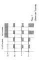
- FIG. 1 Figure 9 is a timing diagram of the prior art modulation signals and Hall voltage.
- FIG. 1 In the half periods of the modulation signal in which no current flows between the first pair of electrical terminals of the Hall element, the resulting Hall voltage is zero. Provided that a current flows between the first pair of electrical terminals, a resulting magnetic flux density can deflect the electrons and thus a Hall voltage can be measured between the second pair of electrical terminals.
- the magnetic flux density is the sum of the magnetic flux densities of the extraneous field of the magnetic device and the target, resulting in that in the half-periods in which a Hall voltage is measured and an extraneous field exists, it can not be distinguished which portions of the Hall voltage from the magnetic flux density of the extraneous field (noise signal) and which are caused by the magnetic flux density of the magnetic device and the target. A reliable decision regarding the presence or absence of a target are thus not possible here.
- FIG. 2 A timing chart of the modulation signals and the Hall voltage in current commutation according to a first method of the present invention is shown in FIG FIG. 2 shown.
- the magnetic device is modulated with a first frequency generator and a square wave signal such that in the first half period of the modulation signal the magnetic flux density is zero and in the second half period of the modulation signal the magnetic flux density assumes the constant value.
- the current source is frequency-modulated with a second frequency generator in such a way with a mean value-free square wave signal that the direction of the current flow between the first pair of electrical connections is commutated in successive half periods of the modulation signal.
- the two frequency encoders are coordinated so that the modulation signals are in phase with each other and correlate the transitions between the half periods in time.
- the Hall voltage measured in the first half-cycle is influenced by the current flow and the magnetic flux density of the extraneous field. If, in the idealized case, no external field is present in these half-periods, then the measured Hall voltage is equal to zero. If, however, an external field is present in the half-periods, then a Hall voltage is measured, which depends only on the magnetic flux density of the external field and can be referred to as a noise signal.
- the measured Hall voltage depends on the resulting magnetic flux density B R and changes the commutation of the current direction also the sign.
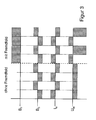
- FIG. 3 is a timing diagram of the modulation signals and the Hall voltage at current commutation and mean-free magnetic flux density B S according to a second method of the present invention.
- the magnetic device and the current flow between the first pair of electrical connections of the Hall element in such a manner with a frequency generator, for example with a mean square wave, modulated that in the first half-period of the modulation signal, the magnetic flux density of the magnetic device in a first direction and the current flow between the first pair of electrical terminals is in a first direction.
- a frequency generator for example with a mean square wave
- the magnetic flux densities of the external field and the magnetic device overlap alternately in an amplifying and attenuating manner in successive half periods of the modulation signal.
- the sign of the Hall voltage measured in each half-cycle changes, so that a continuous integration of the Hall voltages measured in each half-cycle leads to a doubling of the sensitivity.
- the fraction of the external field is eliminated by the current commutation and integration of the Hall voltage over at least two half periods. If the current integration value is continuously compared with a predetermined reference value, a difference signal can be provided, by means of which a reliable decision regarding the presence or absence of a target is possible.
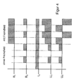
- FIG. 4 A time chart of the modulation signal and the Hall voltage at which the mixture is time-shifted according to a third method of the present invention is shown in FIG FIG. 4 shown.
- a current flows between the first pair of electrical terminals in one direction, so that the current direction and intensity is constant over all half periods of the modulation signal.
- the magnetic flux density of the magnetic device is modulated in such a way that, in two successive half-periods, the magnetic flux density alternately assumes the value zero and a value which is constant for the measuring duration.
- Measuring the Hall voltage between the second pair of electrical connections of the Hall element in each half-period of the modulation signal because of the constant current direction, leads to measured values with a constant sign.
- the stored Hall voltages are alternately multiplied by -1 and +1.
- the resulting resulting Hall voltages U R are then integrated over the duration of the measurement, which also suppresses the proportion influenced by the foreign field.
- a continuous comparison of the current integration value with a predetermined reference value and providing a difference signal allows a reliable decision regarding the presence or absence of a target.
Landscapes
- Measuring Magnetic Variables (AREA)
Applications Claiming Priority (1)
| Application Number | Priority Date | Filing Date | Title |
|---|---|---|---|
| DE201010001076 DE102010001076A1 (de) | 2010-01-21 | 2010-01-21 | Induktiver Näherungssensor und Verfahren zur Näherungsmessung |
Publications (1)
| Publication Number | Publication Date |
|---|---|
| EP2348637A1 true EP2348637A1 (fr) | 2011-07-27 |
Family
ID=43856002
Family Applications (1)
| Application Number | Title | Priority Date | Filing Date |
|---|---|---|---|
| EP11151570A Withdrawn EP2348637A1 (fr) | 2010-01-21 | 2011-01-20 | Capteur de rapprochement inductif et procédé de détection de rapprochement |
Country Status (2)
| Country | Link |
|---|---|
| EP (1) | EP2348637A1 (fr) |
| DE (1) | DE102010001076A1 (fr) |
Cited By (1)
| Publication number | Priority date | Publication date | Assignee | Title |
|---|---|---|---|---|
| WO2012055914A1 (fr) * | 2010-10-27 | 2012-05-03 | Ifm Electronic Gmbh | Commutateur de proximité inductif |
Families Citing this family (1)
| Publication number | Priority date | Publication date | Assignee | Title |
|---|---|---|---|---|
| GB2518255A (en) | 2013-09-13 | 2015-03-18 | Vodafone Ip Licensing Ltd | Communicating with a machine to machine device |
Citations (3)
| Publication number | Priority date | Publication date | Assignee | Title |
|---|---|---|---|---|
| WO2005010543A1 (fr) * | 2003-07-30 | 2005-02-03 | Koninklijke Philips Electronics N.V. | Dispositif du type capteur magnetique monte sur puce et caracterise par une suppression de la diaphonie |
| WO2007105143A2 (fr) * | 2006-03-15 | 2007-09-20 | Koninklijke Philips Electronics N. V. | Système de capteur à champs d'excitation alternés |
| WO2007132372A1 (fr) * | 2006-05-09 | 2007-11-22 | Koninklijke Philips Electronics N. V. | Dispositif de détection magnétique et procédé de détection de particules magnétiques |
Family Cites Families (5)
| Publication number | Priority date | Publication date | Assignee | Title |
|---|---|---|---|---|
| US5534849A (en) * | 1993-08-11 | 1996-07-09 | Sentrol, Inc. | Time multiplexed, false alarm resistant magnetically actuated security system |
| US5488294A (en) * | 1995-01-18 | 1996-01-30 | Honeywell Inc. | Magnetic sensor with means for retaining a magnet at a precise calibrated position |
| US5818222A (en) * | 1995-06-07 | 1998-10-06 | The Cherry Corporation | Method for adjusting ferrous article proximity detector |
| DE19959233B4 (de) * | 1999-12-08 | 2007-12-13 | Tiefenbach Gmbh | Induktiver Sensor zum Erfassen von Metallteilen |
| DE10135264A1 (de) * | 2001-07-19 | 2003-01-30 | Eckart Hiss | Schaltoszillator |
-
2010
- 2010-01-21 DE DE201010001076 patent/DE102010001076A1/de not_active Withdrawn
-
2011
- 2011-01-20 EP EP11151570A patent/EP2348637A1/fr not_active Withdrawn
Patent Citations (3)
| Publication number | Priority date | Publication date | Assignee | Title |
|---|---|---|---|---|
| WO2005010543A1 (fr) * | 2003-07-30 | 2005-02-03 | Koninklijke Philips Electronics N.V. | Dispositif du type capteur magnetique monte sur puce et caracterise par une suppression de la diaphonie |
| WO2007105143A2 (fr) * | 2006-03-15 | 2007-09-20 | Koninklijke Philips Electronics N. V. | Système de capteur à champs d'excitation alternés |
| WO2007132372A1 (fr) * | 2006-05-09 | 2007-11-22 | Koninklijke Philips Electronics N. V. | Dispositif de détection magnétique et procédé de détection de particules magnétiques |
Cited By (1)
| Publication number | Priority date | Publication date | Assignee | Title |
|---|---|---|---|---|
| WO2012055914A1 (fr) * | 2010-10-27 | 2012-05-03 | Ifm Electronic Gmbh | Commutateur de proximité inductif |
Also Published As
| Publication number | Publication date |
|---|---|
| DE102010001076A1 (de) | 2011-07-28 |
Similar Documents
| Publication | Publication Date | Title |
|---|---|---|
| DE69804857T2 (de) | Integritätsprüfung von elektroden | |
| DE3632624C1 (de) | Stoerfeldunempfindlicher Naeherungsschalter | |
| EP2666023B1 (fr) | Appareil de mesure de courant | |
| EP2291665B1 (fr) | Dispositif de détection de courant conçu pour mesurer des courants dans un conducteur primaire | |
| DE19543562A1 (de) | Anordnung zur berührungslosen Drehwinkelerfassung eines drehbaren Elements | |
| DE60121148T2 (de) | Sensor zur messung von positionen und elektromagnetischen feldern | |
| WO2010084000A1 (fr) | Procédé pour générer un signal de mesure électrique par induction, et dispositif de détection correspondant | |
| DE3840532A1 (de) | Verfahren zur induktiven erzeugung eines elektrischen messsignals zur bestimmung des weges und/oder der position im raum und/oder von materialeigenschaften eines pruefkoerpers und nach diesem verfahren aufgebauter naeherungssensor und verwendung desselben als naeherherungsschalter | |
| DE10153884A1 (de) | Selbstkompensierende Steuerschaltung für digitale Magnetsensoren | |
| WO2010069284A2 (fr) | Ensemble circuit et procédé destiné à l'évaluation d'un capteur | |
| EP2066997B1 (fr) | Mesure de distance par champ magnétique commandé | |
| EP3893006B1 (fr) | Agencement de circuits électriques et procédé de mesure de courant différentiel galvaniquement isolée, sensible à tous les courants, à haute résolution | |
| DE102021104752B4 (de) | Stromsensor für die berührungslose strommessung | |
| EP2348637A1 (fr) | Capteur de rapprochement inductif et procédé de détection de rapprochement | |
| EP2435794B1 (fr) | Dispositif et procédé pour déterminer une position angulaire | |
| DE10123539B4 (de) | Magnetische Längenmessvorrichtung | |
| DE102004025388B4 (de) | Verfahren und Vorrichtung zur Ermittlung der Position und/oder einer oder mehrerer Bewegungsgrößen eines Gegenstandes | |
| EP2633623B1 (fr) | Commutateur de proximité inductif | |
| EP1093224A2 (fr) | Détecteur d'impulsions et procédé pour la détection d'impulsions sinusoidales | |
| DE102004025387B4 (de) | Magnetostriktive Wegaufnehmervorrichtung | |
| DE19908361A1 (de) | Sensorvorrichtung zur Erfassung von Geschwindigkeit und Bewegungsrichtung eines Objektes, insbesondere von Drehzahl und -richtung eines rotierenden Objektes | |
| DE10216635A1 (de) | Bewegungsdetektor nach dem Ferrarisprinzip | |
| EP3279653A1 (fr) | Dispositif et procede destines a la determination non destructive de la teneur de la partie magnetisable et/ou non magnetisable d'un echantillon | |
| EP1996900A1 (fr) | Capteur de mesure de course par le biais du dephasage du champ magnetique dans le cas d`un ligne a retard rc | |
| DE3824267C2 (fr) |
Legal Events
| Date | Code | Title | Description |
|---|---|---|---|
| PUAI | Public reference made under article 153(3) epc to a published international application that has entered the european phase |
Free format text: ORIGINAL CODE: 0009012 |
|
| AK | Designated contracting states |
Kind code of ref document: A1 Designated state(s): AL AT BE BG CH CY CZ DE DK EE ES FI FR GB GR HR HU IE IS IT LI LT LU LV MC MK MT NL NO PL PT RO RS SE SI SK SM TR |
|
| AX | Request for extension of the european patent |
Extension state: BA ME |
|
| STAA | Information on the status of an ep patent application or granted ep patent |
Free format text: STATUS: THE APPLICATION IS DEEMED TO BE WITHDRAWN |
|
| 18D | Application deemed to be withdrawn |
Effective date: 20120128 |