EP2348639A2 - Codage et décodage de données pour la transmission à travers un canal de transmission erroné - Google Patents
Codage et décodage de données pour la transmission à travers un canal de transmission erroné Download PDFInfo
- Publication number
- EP2348639A2 EP2348639A2 EP10015960A EP10015960A EP2348639A2 EP 2348639 A2 EP2348639 A2 EP 2348639A2 EP 10015960 A EP10015960 A EP 10015960A EP 10015960 A EP10015960 A EP 10015960A EP 2348639 A2 EP2348639 A2 EP 2348639A2
- Authority
- EP
- European Patent Office
- Prior art keywords
- data
- code
- block
- transfer
- packet
- Prior art date
- Legal status (The legal status is an assumption and is not a legal conclusion. Google has not performed a legal analysis and makes no representation as to the accuracy of the status listed.)
- Ceased
Links
Images

Classifications
-
- H—ELECTRICITY
- H03—ELECTRONIC CIRCUITRY
- H03M—CODING; DECODING; CODE CONVERSION IN GENERAL
- H03M13/00—Coding, decoding or code conversion, for error detection or error correction; Coding theory basic assumptions; Coding bounds; Error probability evaluation methods; Channel models; Simulation or testing of codes
- H03M13/03—Error detection or forward error correction by redundancy in data representation, i.e. code words containing more digits than the source words
- H03M13/05—Error detection or forward error correction by redundancy in data representation, i.e. code words containing more digits than the source words using block codes, i.e. a predetermined number of check bits joined to a predetermined number of information bits
- H03M13/09—Error detection only, e.g. using cyclic redundancy check [CRC] codes or single parity bit
Definitions
- the present invention relates to the encoding and decoding of data for transmission over a faulty transmission channel.
- the invention relates to the prevention or correction of transmission errors.
- Channel coding is, for example, a method in which digital data for transmission over disturbed channels is protected by adding redundancy against transmission errors or at least the transmission errors are detected. If the redundant overhead information merely indicates an error and requires retransmission of the data, this is referred to as backward error correction. If the redundancy information is sufficient to correct the error and if a detected error after the transmission is corrected from the incorrectly transmitted data by means of the redundant additional information, this is a forward error correction.
- the code rate R kln is the ratio of the number k of symbols of the information to be transmitted before encoding, ie the amount of useful data, to the number n of symbols after encoding, ie the number n of code symbols that actually exceeds the faulty channel to be transported.
- k information symbols are mapped to n code symbols.
- a low code rate corresponds essentially to a large amount of redundancy in the transmitted code data.
- the bit error rate is the ratio of the number of bits erroneously transmitted through an information channel to the number of bits transmitted.
- a channel code with a low code rate can correct more errors than a comparable channel code with a high code rate.
- a small code rate (large n) means a smaller proportion of useful information density. At a given transmission rate of the channel or channel data rate, this leads to a smaller usable data rate or payload data rate.
- Block codes represent a type of channel coding in which the codewords used all have the same number of symbols.
- block codes often are not optimal in terms of minimum mean codeword length, often restricting themselves to block codes, since the processing of variable length codes is usually more expensive.
- the required computing power in coding and decoding as well as in the error correction often plays an important role.
- the computing power and the required processing time is also a significant factor for block codes, such as the Reed-Solomon codes, especially for real-time transmissions.
- Another known error protection mechanism is the so-called interleaving.
- the symbols for forming a codeword are not consecutive taken from the data stream of the information to be transferred, but symbols at a distance of the respective interleaving distance or the interleave factor or the interleaving rate are combined to form a codeword.
- the effects of a so-called burst error ie the disturbance of several consecutive symbols, can be minimized.
- resorting the data requires a certain amount of latency, both in the sender and in the receiver, due to the fact that always first some amount of data has to be awaited before the process of resorting within that amount of data can be started or completed. Especially for real-time transmissions, this additional delay plays a not insignificant role.
- audio codec devices transmit audio data streams e.g. from a local reporter to the broadcast house via communication networks, e.g. via UMTS and / or ISDN. Transmission of data often results in transmission errors.
- Object of the present invention is to improve the digital data transmission over a faulty digital channel, in particular with regard to a fast transmission with a high efficiency of the error correction with low computational effort.
- This object is achieved by a coding and a decoding method, a transmitter and a receiver and a computer program product having the features specified in the independent claims. Preferred embodiments are subject of the dependent claims.
- the invention particularly provides a coding method for coding a digital data record (hereinafter also referred to as information data record), in particular for transmitting the data or information via a (defective) data channel or transmission channel, the method comprising: dividing the data record into a Variety of information data packets, wherein each information data packet comprises a plurality of data elements.
- data elements preferably represent a smallest unit of separately manipulated data, such as a byte or a bit.
- a bit is often used as preferred embodiments of the data elements.
- a data element may occupy two states, often represented as "0" and "1".
- the method comprises generating a redundancy data packet for each information data packet such that the redundancy data packet contains at least one data element dependent on the data elements of the respective information data packet as a redundancy data element (e), e.g. in the form of a parity bit.
- the redundancy data packet is generated in particular from the respective information data packet.
- the redundancy data packet contains parity data, such as e.g. one or more parity bits generated from the data of the respective information data packet.
- the data encompassed by the redundancy data packet provide redundancy such that at least a minimum amount of information loss can be recovered from the information data packet taking into account the associated redundancy data packet.
- the term "packet" in the redundancy data packet does not necessarily mean that it must contain more than one redundancy data element.
- the redundancy data packets are each formed by a parity bit.
- the method comprises a combination of a plurality of information data packets with the respectively generated redundancy data packet and a reference data block to a code data block, wherein the reference data block predefined, ie independent of the data record to be transmitted, data elements contains as reference data or in particular consists of such predefined reference data.
- the code data block in each case an information data packet and the associated redundancy data packet are combined to form a code data packet or arranged together.
- the multitude of code data packets together with the a reference data block thus form the code data block.
- the reference data block in the code data block is preferably arranged as a contiguous data block, which is in particular preceded or adjusted by the plurality of code data packets.
- the reference data block represents a set of known or predetermined or data elements, such as a fixed bit sequence, which is known in particular in a data transmission both the transmitter (for coding) and the receiver (for decoding).
- the reference data block comprises a number of data elements, which is specified as a reference block size CS .
- About a possible change of the reference data block in the data transfer can be located preferably the occurrence and the position of any transmission errors in the record. This will be explained in detail below.
- the method comprises resorting a plurality of data elements within the code data block according to a coding sorting rule to obtain a transfer data block.
- This transfer data block thus represents at least part of the coded data of the original digital data set.
- further code data blocks are formed in an analogous or identical manner and resorted according to the coding sorting rule in order to form further transfer data blocks.
- the reordered code data blocks thus form transfer data blocks, which together constitute a transfer data record which is transmitted via a digital data channel, such as a digital data channel.
- UMTS can be sent or transmitted.
- the transmission of the transfer data record via a digital channel comprises transmitting the transfer data record from a UMTS network to an ISDN network.
- the invention provides a corresponding decoding method for decoding a transmitted digital data record (hereinafter also referred to as transfer data record) which has been coded in particular according to a method according to the invention, in particular in a preferred embodiment.
- the decoding method comprises a detection at least one transfer data block from the transmitted data record, wherein the transfer data block comprises a plurality of data elements, in particular a plurality of bits.
- the decoding method comprises determining a code data block by resorting a plurality of data elements within the acquired transfer data block according to a decoder sorting rule.
- the decoder sorting rule represents a rule inverse to the coding sorting rule, i.
- the decoder sorting instruction and the coding sorting instruction together again lead back to the output structure, i. Together they form the identity picture.
- the decoding method comprises identifying a reference data block and a plurality of code data packets in the code data block, wherein each code data packet comprises an information data packet and a redundancy data packet.
- the assignment of the individual data elements of the reference data block to respective positions in the transfer data block is uniquely determined by the coding sorting rule or the decoding sorting rule. The same applies to the data elements of the information data packets and the redundancy data packets.
- the decoding method comprises determining at least one erroneous data element in at least one erroneous information data packet from a deviation of at least one data element of the reference data block from a predefined value, and correcting the transmission error by means of the redundancy data packet associated with the erroneous information data packet.
- the invention achieves a fast transmission of digital data with a high efficiency of error correction with low computational effort.
- the invention provides a significant improvement in terms of the required computing power and thus the necessary hardware resources.
- the latency of data transmission can be kept relatively low even at high code rate. This is especially desirable for real-time transmissions.
- audio data streams via UMTS and / or ISDN can be transmitted particularly efficiently.
- the audio errors which conventionally occur during transmission by means of a UMTS CS carrier channel have already been substantially reduced with only a small amount of computation.
- the invention recognized in particular that the proposed method can be used particularly efficiently in a data transmission in the transmission channel from UMTS to another network, eg ISDN and vice versa.
- the specific error characteristic of this transmission channel is very effectively counteracted with the proposed methods.
- the conventionally clearly audible audio errors are largely attributable to block errors or burst errors distributed at random intervals, and that these can be efficiently corrected by means of the invention. Further details about particular preferred parameters for this particular transmission channel are further below.
- each information data packet consists of a number of logically adjacent or directly successive data elements in the data record (also referred to as information data set) which correspond to a predetermined value of one, ie for all information data packets
- Information package size PS corresponds.
- the generation of a redundancy data packet for each information data packet is preferably carried out in such a way that each redundancy data packet consists of a number of data elements which corresponds to a predetermined value of a redundancy packet size RS which is the same for all redundancy data packets.
- the respective redundancy data packet is formed by a parity bit, ie the redundancy data packet is ordered from a single data element, namely a single bit as a redundancy data element.
- the redundancy packet size RS is thus preferably 1. In other embodiments, however, redundancy packet sizes RS of 2 or more are also possible, ie the redundancy data packet comprises a multiplicity of bits in these embodiments. Preferably, the redundancy data packet in these embodiments consists of these plurality of bits.
- the combination of a plurality of information data packets with the respectively generated redundancy data packet and a reference data block to a code data block is preferably carried out in such a way that the code data block consists of a number of data elements corresponding to an integer multiple of a predetermined value of an error block size ES which is the same for all code data blocks ,
- the code data block consists of a number of data elements which corresponds to a product of the value of the error block size ES and the value of a code packet size DS , the value of the code packet size DS resulting from the sum of the values of the information packet size PS and the redundancy packet size RS.
- the number of data elements in the code data block is also called code data block size BS below.
- resorting the plurality of data items within the code data block includes an interleaving process having a predetermined interleaving rate N and an interleaving block length corresponding to the number of data items in the code data block.
- an interleaving process with an interleaving rate N and an interleaving block length IS a re-sorting of a series of IS characters (S 1 , S 2 , S 3 ,..., S N-1 , S N , S N + 1 , ...
- the resulting resorted series is thus in particular: (S 1 , S N + 1 , S 2N + 1 , ... S 2 , S N + 2 , S 2N + 2 , ..., S 3 , ).
- predetermined or predetermined permutations of the subseries (S 1 , S N + 1 , S 2N + 1 , ...), (S 2 , S N + 2 , S 2N + 2 , ...) should preferably also still fall under the meaning of the interleaving process within the meaning of the invention.
- the interleaving rate N coincides with the value of the code packet size DS .
- N transfer data sections which are connected in the transfer data record N are preferably generated in such a way that in each case the first or the second etc. data elements of all the information data packets are assigned together to a transfer data section. The same applies to the data elements of the redundancy data packets.
- the reference block size CS should be at least as large as the interleaving rate N in order to assign at least one data element of the reference data block to each transfer data section.
- the reference block size CS is significantly larger than the interleaving rate N, preferably at least 4 times as large, even more preferably at least 16 times as large.
- the bit error rate can be reduced with increasing reference block size CS .
- the reference block size CS is preferably not larger than 75% of the code data block size BS , more preferably not larger than half of the code data block size BS .
- the decoding preferably comprises comparing the data elements of the reference data block determined in the code data block with a predefined value (setpoint values) for the respective data elements in order to determine deviations.
- the data error block is determined to consist of a number of data elements corresponding to a predetermined value of an error block size ES.
- transmitting the transfer record via a digital channel comprises transmitting the transfer record from a UMTS network to an ISDN network.
- the coding device thus comprises an interleaver module for creating the transfer data block by means of an interleaving process.
- the transmitting device is designed for transmitting the transfer data block into a UMTS network.
- the receiving device for receiving the transfer data set is designed from an ISDN network.
- the invention relates to a coding method for coding a digital data record.
- the method in this case comprises generating a plurality of code data blocks from the data record and generating a transfer data sequence from the plurality of code data blocks such that the transfer data sequence for each code data block in addition to the code data block also comprises an identical code block duplicate.
- Each code block duplicate is therefore identical to a code data block at least before the transfer of the transfer data sequence via a possibly faulty transmission channel.
- the code block duplicates in the transfer data sequence are arranged logically and / or temporally, indirectly or directly, ie with or without a logical or temporal distance, behind or after the corresponding code data block, ie in particular after corresponding code data block transmitted. In particular, they represent an exact copy of the respective code data block.
- the first or earlier of the two matching data blocks is referred to as code data block (or first code data block) and the second or later as code block duplicate (or second code data block).
- generating a plurality of code data blocks from the data set comprises generating a plurality of code data packets from the data set and merging a plurality of code data packets into a code data block.
- the transfer data sequence is thus generated in such a way that it comprises a multiplicity of code data packets and, for each code data packet, an identical code packet duplicate.
- the first or earlier of the two matching data packets is referred to as code data packet (or first code data packet) and the second or later as code packet duplicate (or else second code data packet).
- a multiplicity of code packet duplicates is combined to form a code block duplicate.
- the logical and / or temporal order of the code packet duplicates in the code block duplicates corresponds to the respective logical or temporal order of the corresponding code data packets in the corresponding code data blocks.
- all code data blocks and all code block duplicates are formed from the same number of code data packets or code packet duplicates. More preferably, the generation of a plurality of code data packets is carried out in such a way that each code data packet consists of a number of data elements that corresponds to a predetermined value of an error block size ES that is the same for all code data packets.
- all code data blocks and all code block duplicates have the same size.
- the transfer data sequence is generated such that the code data blocks and the code block duplicates alternate logically and / or temporally are arranged, that is followed in alternation always a code data block and a code block duplicate.
- the transfer data sequence is generated such that for each code data block the associated code block duplicate within the transfer data sequence is arranged logically and / or temporally immediately behind or after the respective code data block, i. the matching data blocks follow one another directly, without interposing another data block, for example in the form of a code data block or a code block duplicate, for example of the same length or larger or larger.
- generating a plurality of code data packets from the data set comprises dividing the data set into a plurality of information data packets, each information data packet comprising a plurality of data elements.
- generating the plurality of code data packets preferably comprises generating one code data packet each from one of the plurality of information data packets such that each code data packet comprises redundancy information dependent on the respective information data packet.
- generating a code data packet for each information data packet comprises generating a cyclic redundancy check (e.g., CRC16) check packet.
- each code data packet comprises 1280 bits, preferably 1264 bits of payload data and 16 bits of redundancy information (e.g., CRC16), e.g.
- each information data packet comprises 1264 bits and each test packet 16 bits.
- each code data block and each code block duplicate comprises 4 code data packets or 4 code packet duplicates.
- the generated transfer data sequence is preferably transmitted or transmitted via a digital data channel, such as UMTS.
- a digital data channel such as UMTS.
- Transferring the transfer data sequence via a digital channel comprises transmitting the transfer data sequence from a UMTS network to an ISDN network.
- the invention provides a corresponding decoding method for decoding a transmitted digital data record, which is also to be referred to as a transfer data record and which has been coded in particular according to a method according to the invention, in particular in a preferred embodiment.
- the decoding method comprises detecting at least one transfer data sequence from the transmitted data record, the transfer data sequence comprising a plurality of data elements, in particular a plurality of bits.
- the transfer data sequence comprises the plurality of data elements in the form of a plurality of code data packets and a plurality of code packet duplicates.
- the code data packets and the code packet duplicates have the same size or length, ie in each case the same number of data elements.
- the decoding method comprises determining at least one first code data packet and at least one code packet duplicate corresponding thereto as the second code data packet in the acquired transfer data sequence.
- the second code data packet in the transfer data sequence corresponds to a data packet which was generated as a copy of the first code data packet when the transfer data sequence was created before it was transmitted.
- at least one of the two code data packets could be changed and thus be faulty.
- the two code data packets are determined in particular as part of a first or a second code data block, which are also referred to as code data block and code block duplicate, in the data transfer sequence.
- They are particularly preferably determined as sections in the data transfer sequence whose beginning in the data transfer sequence are shifted logically and / or temporally relative to one another by a predetermined duplicate shift, the predetermined duplicate shift in particular of the logical or temporal length of the Code data blocks corresponds.
- the decoding method comprises checking a consistency of at least one of the two determined code data packets.
- the consistency is checked, in particular, via the redundancy inserted in the coded data packets determined according to a predetermined coding method during the generation of the code data packets during coding.
- the method comprises determining an information data packet from the at least one checked code data packet, if its consistency has been determined, or determining an information data packet from the other of the two determined code data packets, if the Consistency of the at least one checked code data packet was not detected. Checking the consistency of the other of the two coded data packets determined is not absolutely necessary.
- the consistency is also checked in order to check the accuracy of the information data packet determined. If no consistency is found for either of the two code data packets, error-free determination of the information data packet from one of the code data packets may not be possible. In this case, a possibly erroneous information data packet is preferably determined from one of the two code data packets. The determined information data packet is finally assigned to an information data record.
- the steps of determining at least a first and a second code data packet, verifying the consistency of at least one of the determined code data packets, checking dependent determination of an information data packet, and associating the determined information data packet with an information data set are preferably performed for all code data packets and data packets contained in the acquired transfer data sequence Code packet duplicates performed.
- the invention achieves a particularly efficient and Fast transmission of digital data with a very reliable error correction with low computational effort.
- the invention is characterized in its use for the transmission of audio data streams via UMTS and / or ISDN, especially in a data transmission in the transmission channel of UMTS in another network, eg ISDN, (so-called "uplink") by the combination of low required computing power and low latency of the data transmission.
- uplink a data transmission in the transmission channel of UMTS in another network
- uplink e.g ISDN
- transmitting the transfer data sequence over a digital channel comprises transmitting the transfer data sequence from a UMTS network to an ISDN network.
- the coding device is designed to carry out a coding method according to one of the described preferred embodiments of the invention, wherein the transmitting device is preferably designed for transmitting the transfer data sequence or a transfer data block into a UMTS network.
- the coding device is designed to be switched over between different operating modes, in which the coding device in each case executes one of the coding methods according to the invention, in particular in one of the described preferred embodiments.
- the transmitter preferably has a switching device in order to switch between the different operating modes.
- the decoding device is designed to carry out a decoding method according to one of the described preferred embodiments of the invention, wherein the receiving device is preferably designed to receive the transfer data sequence or a transfer data record from an ISDN network.
- the decoding device is designed to be switched over between different operating modes, in which the decoding device in each case executes one of the decoding methods according to the invention, in particular in one of the described preferred embodiments.
- the receiver preferably has a switching device in order to switch between the different operating modes.
- the transfer data sequence is generated such that a code block duplicate of another code data block is arranged therein (logically and / or temporally) immediately after or after each code data block.
- the transfer data sequence is preferably generated from a plurality of code transfer blocks, wherein each code transfer block is composed in particular of one code data block and one code block duplicate corresponding to another code data block.
- each code transfer block is composed in particular of one code data block and one code block duplicate corresponding to another code data block.
- the generation of a transfer data sequence thus preferably includes creating the plurality of code transfer blocks and logically and / or temporally juxtaposing the code transfer blocks.
- code data blocks and code block duplicates are preferably arranged alternately in the transfer data sequence, each code block duplicate being removed from the associated (ie identical or identical) code data block by a particular predetermined, ie identical or constant, logical and / or temporal duplicate delay or duplicate delay for all code data blocks . is spaced.
- the order of the code block duplicates in the transfer data sequence preferably corresponds to the order of the corresponding code data blocks.
- the beginning of each code block duplicate is shifted logically and / or temporally back by the predetermined duplicate delay or duplicate delay relative to the end of the associated code data block.
- the predetermined duplicate shift or duplicate delay specifies, in particular, a predetermined logical (in particular in a number of bits) and / or temporal (in particular in seconds or milliseconds) distance between a code data block and the associated code block duplicate.
- the duplicate delay preferably corresponds to an integer multiple, in particular an even multiple, of the size or length of a code data block, or the duplicate delay is defined as an integer, in particular even multiple of the size or length of a code data block.
- a front corresponding code transfer block substantially to each code transfer block such that the code block duplicate comprised by the code transfer block matches the code data block comprised by the front corresponding code transfer block
- a back corresponding code transfer block comprises that of the code transfer block Code block corresponding to the code block duplicate included in the rear corresponding code transfer block.
- Corresponding code transfer blocks thus preferably always have the same logical and / or time intervals from one another. In particular, the beginning of corresponding code transfer blocks is shifted relative to one another by the duplicate shift or duplicate delay. The same applies in principle to their end.
- generating the plurality of code data blocks from the data set preferably comprises dividing the data elements contained in the data set into a plurality of information data blocks. More preferably, the data elements (e.g., bits or bytes) contained in the data set are sequentially grouped and preferably used directly as code data blocks in the logical and / or temporal order defined therein to generate the plurality of preferably equal size information data blocks.
- further coding steps in particular the insertion of additional redundancy in the generation of code data blocks from the information data blocks, are dispensed with here. As a result, with surprisingly good error correction, a comparatively small amount of computation is required.
- the invention provides a corresponding decoding method for decoding a transmitted digital data record, which has been coded in particular according to a method according to the invention, in particular in one of the preferred embodiments just described.
- the decoding method in this case comprises detecting a transfer data sequence from the transmitted data record, the transfer data sequence comprising a plurality of, in particular, identical code transfer blocks such that each code transfer block comprises a code data block and a code block duplicate.
- a front corresponding code transfer block such that the code block duplicate comprised by the code transfer block corresponds to the code data block comprised by the front corresponding code transfer block, ie, is agreed by the encoding / decoding rule as coinciding in error-free transmission
- a back corresponding code transfer block such that the code data block comprised by the code transfer block is from the code block corresponding code transfer block comprised code block duplicate corresponds, that is determined by the encoding / decoding rule as coincident in error-free transmission.
- the decoding method comprises comparing the code data block of a first code transfer block with the code block duplicate of a second code transfer block, wherein the beginning of the second code transfer block in the detected transfer data sequence by a predetermined duplicate shift, in particular by a predetermined number of data blocks and / or data elements (eg bits) Beginning of the first code transfer block is logically and / or temporally removed, so in particular is shifted backwards. That the second code transfer block starts in the transfer data sequence logically and / or in time by the predetermined duplicate shift further back or later than the first code transfer block. Specifically, it is determined by the comparison whether the first code transfer block represents the front corresponding code transfer block to the second code transfer block, and the second code transfer block, respectively, represents the rear corresponding code transfer block to the first code transfer block.
- the method in particular makes it possible to determine the absence of one or more data blocks, in particular data blocks or data segments with a length which corresponds to the length of one or more code transfer blocks, in the transfer data sequence.
- the decoding method comprises determining an information data block from the code data block of the first code transfer block and, depending on whether substantially coincidence of the code data block of the first code transfer block with the code block duplicate of the second code transfer block has been determined in the step of comparing or from the code block duplicate of the second code transfer block, if a match was found in the step of comparing, or determining an information data block from the code data block of the first code transfer block and determining a further information data block from the code block duplicate of a third code transfer block, wherein the logical and / or or temporally beginning of the third code transfer block in the detected transfer data sequence by the predetermined duplicate shift from the beginning of the second code transfer block logically and / or r is temporally removed, that is, in particular displaced to the rear, if in the step of comparing substantially no match has been found.
- the third code transfer block corresponds in particular to the rear corresponding code transfer block of a codetransfer block at least partially lost in the transmission.
- the information contained in the code data block of the at least partially lost code transfer block is in particular once again contained in the code block duplicate of the third code transfer block and is used accordingly for the reconstruction of the information data record.
- the decoding method detects an assignment of the determined information data blocks to an information data record.
- the information data in the code data blocks or code block duplicates are not further encoded or encrypted, in particular by an additional redundancy, the data elements of the respective code data block or code block duplicate are used directly as data elements of the corresponding Taken over information data block. Otherwise, they are determined according to the corresponding additional encoding / decoding process.
- the code data block of the first code transfer block is in particular "essentially" identical to the code block duplicate of the second code transfer block if the differences or deviations from an exact match, ie from a complete identity, are smaller or at least not greater than specified in predetermined error tolerance criteria.
- a number of data elements, in particular bits are defined as error tolerance criteria as a tolerance limit for deviations which are still permitted or no longer permitted. If the number of differing data elements determined during the comparison is below or at least not above this tolerance limit value, the compared data blocks are considered as "substantially" identical.
- fault tolerance criteria may stipulate that no single data element may deviate if "substantially" a match is to be determined. Especially in this case, the fault tolerance criteria need not be specified explicitly, ie as a separate parameter value. Rather, in this case, the fault tolerance criteria may be considered implicit in the identity comparison.
- the invention achieves a particularly efficient and fast transmission of digital data with a very reliable error correction with low computational effort.
- the invention is characterized in its use for the transmission of audio data streams via UMTS and / or ISDN, especially in a data transmission in the transmission channel in a UMTS network from another network, eg ISDN, (so-called "downlink") by the combination low required computing power and low latency of the data transmission.
- the specific error characteristic of this transmission channel is very effectively counteracted with the proposed methods.
- the conventionally clearly audible audio errors are largely attributable to missing, ie lost, data blocks at random intervals and with block lengths which correspond to an integer multiple of a minimum block length, and that these can be corrected efficiently by means of the invention.
- the length or size of the code transfer blocks in particular the minimum block length of the occurring block errors is provided, i. the code data blocks and the code block duplicates are provided with a size or length that corresponds to half the size or length of the minimum block errors.
- the minimum block length of the block errors occurring is a value of 80 bytes or 640 bits.
- the length of the code data blocks and code block duplicates is thus preferably a value of 40 bytes or 320 bits.
- a value is used, which corresponds to a size or length of 8 code blocks or code block duplicates, so preferably a size or length of 4 code transfer blocks, in particular 320 bytes or 2560 bits.
- transmitting the transfer data sequence over a digital channel comprises transmitting the transfer data sequence from an ISDN network to a UMTS network.
- the Coding device preferably designed to perform an inventive coding method in particular according to one of the described preferred embodiments.
- the transmitting device is preferably designed for transmitting the transfer data sequence in an ISDN network.
- the decoding device is designed to carry out a decoding method according to the invention, in particular according to one of the described preferred embodiments.
- the invention provides a computer program product, in particular a form of a data carrier or carrier medium, with program code, which, when loaded on a computer system, causes the system to perform one or more steps according to a method of the invention, in particular in a preferred one Execute embodiment.
- Fig. 1 shows an exemplary transmission path or an exemplary transmission channel in which the invention finds application in a particularly preferred manner.
- a transmitter 10 is preferably designed as a mobile device.
- the transmitter 10 is a codec device with mobile radio modem as the transmitting device 11 or, for example, a suitably equipped laptop for transmitting data via a transmission channel, in particular into a UMTS network 12.
- the data is preferably transmitted from the UMTS network 12 via an ISDN network.
- Transmission network 13 to a receiver 14.
- the receiver 14 is preferably designed as a fixed device, in particular as a codec or a suitable PC with a receiving device 15 for receiving the transmitted data.
- this preferred constellation offers a 64 kbit / s connection and preferably uses the usual outband signaling Nr 7 (SS7), which is used regularly in ordinary telephone calls.
- Nr 7 SS7
- a transparent 64 kbit / s channel is established by the mobile transmitter 10 via the radio link and core components of UMTS via ISDN to the receiver 14.
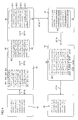
- FIG. 4 a simple example of a corresponding data manipulation according to a preferred embodiment.
- the parameters used for illustration are simplified and only a reduced data set is shown, the principle of encoding, transmission and decoding, including any necessary error correction, can be very well recognized.
- the process starts with an information data set 20 which is present in a source coding with a plurality of data elements in the form of individual bits. Data elements are consistently considered bits in this example and are in Fig. 4 represented as "0" and "1".
- the information data set 20 is divided into a plurality of information data packets (22-1, 22-2, 22-3, 22-4).
- the interleaving rate N can be set by a user and / or it is predetermined in dependence on a selected transmission channel.
- parity bits 24-x are shown throughout as underlined numbers (" 0 " or " 1 ") to facilitate tracking during data manipulation.
- the total number of bits is thereby in step ST10 increased by 1 redundancy bit per 3 information bits.
- the contribution of this change in step ST10 to the code rate is in Fig. 2 as a change factor of the data size.
- this value can be set by a user and / or it is predetermined in particular depending on a selected transmission channel.
- the reference data block 26 is shown in the first line after step ST12 and is described by 16 constant characters "0" in this example.
- This reference data block 26 is known to both the sender and the receiver, and preferably the same for all code data blocks 28 during data transmission.
- the data elements of the reference data block 26 are represented throughout as italic numerals to facilitate tracking during data manipulation.
- the redundancy data packets 24-x after step ST12 continue to be shown in the 4th, 8th, 12th and 16th columns from the 2nd line as underlined numbers.
- step ST14 in FIG Fig. 4 resorting to a plurality of data elements (bits) within the code data block 28, whereby a transfer data block 30 is formed.
- This interleaving process adds no additional data, which is why no change in the code rate results in step ST14 (factor 1 in Fig. 2 ).
- the transfer data block 30 includes a plurality of transfer data sections (32-1, 32-2, 32-3, 32-4) whose size corresponds to the error block size ES.
- Each transfer data section comprises exactly one bit from each code data packet 25-x and additionally one or more data elements (bits) from the reference data block 26.
- the last transfer data section 32-4 contains all parity bits, ie all redundancy data packets 24-x.
- the transfer data block 30 is sent from the transmitter 10 to the transmission channel 34 in a step ST16.
- the transmission channel 34 can now be source for transmission errors.
- burst errors block-wise occurring errors at random intervals
- Fig. 4 shows by way of example the occurrence of a burst error in the second transfer data section 32-x.
- This section is now replaced by an error block 36 whose size corresponds to the error block size ES and thus in particular the size of one or each of the transfer data sections 32-x.
- the second bit in each of the code data packets (corresponding in this case to the second bit of the information data packets 22-x) is destroyed. According to the invention, however, this can be detected and corrected in a decoding process, as will be described below.
- the possibly changed data elements of the error block 36 are shown throughout as bold numerals to facilitate tracking during data manipulation.
- a receiver 14 detects the falsified or erroneous transfer data block 30 'from the transmission channel 34 and re-sorts the data elements (bits), so that in the illustrated example again all the bits of the now corrupted or erroneous reference data block 26' are in the first line.
- This sorting according to a decoder sorting rule is performed in a step ST20 of deinterleaving ( Fig. 3 ). This results in a code data block 28 ', which corresponds to the structure of the code data block 28 before transmission, but may have transmission errors.
- the code data block 28 ' comprises the possibly erroneous reference data block 26' and a plurality of possibly incorrect code data packets 25-x ', which in turn each contain an information data packet 22-x' and a redundancy data packet 24-x '.
- the "constant characters" that is to say the data elements of the reference data block 26 ', are checked. In particular, it is checked whether they correspond to the expected (unchanged or constant) values.
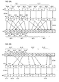
- FIGS. 5A and 5B illustrate another example of the transmission of data, in particular for encoding ( Fig. 5A ) and decoding ( FIG.5B ) of a digital data set according to another preferred embodiment of the present invention.
- the preferred coding method illustrated is based on a digital data record 40 which is subdivided into a multiplicity of preferably uniformly sized information data packets 42-x (42-1, 42-2,).
- each of the information data packets 42-x comprises a plurality of data elements which, in particular in a source coding, contain the information to be coded for transmission.
- the individual information data packets 42-x are marked or distinguished by the letters "a", "b", "c", etc.
- a plurality of information data packets 42-x together form an information data block 44-x (44-1, 44-2,%), from which in a step ST30 a code data block 52-x (52-1, FIG. 52-2, ...) is generated.
- a code data packet 46-x (46-1, 46-2,...) Is generated which, in addition to the information to be transmitted of the respective information data packet 42-x, also contains redundancy information, for example in the form of a test packet 48 -x (48-1, 48-2, ...) of a cyclic redundancy check (eg CRC16). It is thus generated for each information data packet specifically a corresponding redundant check information.
- the information contained in the resulting code data packets including the respective redundancy is in Fig. 5A represented by corresponding capital letters "A", "B", "C”, etc.
- a plurality of code data packets 46-x together form a code data block 52-x, respectively.
- each copy data block 52-1 is logically and / or temporally appended with a copy 54-1 of the same code data block as a code block replica 54-x (54-1, 54-2,. before the next code data block 52-2 follows.
- code data blocks 46-x and code block duplicates 50-x are arranged alternately, whereby in particular every corresponding code block 26-x is followed immediately by the corresponding code block duplicate 50-x.
- the resulting transfer data sequence 56 is then transferred in particular as a transfer data record via a transmission channel, in particular from a UMTS network (12) in an ISDN network (13). Transmission errors may occur during this transmission.
- FIG.5B illustrates a corresponding decoding method for decoding a transmitted and received data set, in particular one received transfer data sequence 56 ', which in particular prior to transmission with a coding method according to the Fig. 5A illustrated preferred embodiment has been generated.
- the received transfer data sequence 56 ' has transmission errors compared with the transfer data sequence 56 generated before the transfer.
- the decoding method comprises detecting a plurality of code data packets 46-x '(46-1', 46-2 ', ...) and for each code data packet 46-x' a corresponding code packet replica 50-x '(50-1', 50 -2 ', ).
- the corresponding pairs of code data packet and code packet duplicate are each denoted by the same capital letter, with the code packet duplicate each being identified by an additional apostrophe.
- the code packet duplicate belonging to a code data packet (eg "A") (eg "A '") is recognized in particular from its logical and / or temporal shift relative to each other. This shift is determined in particular by a predetermined value of a duplicate shift or duplicate delay. It is detected as a first code data packet (eg "A") the corresponding code packet duplicate (eg "A '") as the second code data packet.
- the consistency of the first code data packet "A" is checked on the basis of the redundancy information 48-x 'contained in the first code data packet (eg 48-1') in a step ST34.
- this code data packet "A” is used to restore the original information "a”.
- the information data packet 42-x '(eg 42-1', "a") is determined from the corresponding code data packet 46-x (eg 46-1 '"A"). Checking the consistency of the corresponding code packet duplicate 50-1 '("A'") is not necessary in this case.
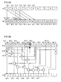
- FIGS. 6A and 6B illustrate another example of the transmission of data, in particular for encoding ( Fig. 6A ) and decoding ( Fig. 6B ) of a digital data set according to another preferred embodiment of the present invention.
- the method can be used particularly efficiently for an application for forward error correction during data transmission, in particular from an ISDN network to a UMTS network.
- Fig. 1 Compared to the explicit description of Fig. 1
- the roles of transmitter and receiver are reversed, ie the device designated by the reference numeral 14 acts as a transmitter, while the device indicated by the reference numeral 10 acts as a receiver.
- This direction is also referred to as "downstream” or “downlink” in particular.
- Fig. 6A illustrates possible errors in the data transmission is met by a double transmission of the same signal.
- Fig. 6A illustrated preferred encoding method in turn from a digital data set 40 to be transmitted.
- This is subdivided into a multiplicity of information data blocks 44-x ("a”, “b”, “c”,...) Having a preferably constant data block size of, for example, 40 bytes each.
- the information data blocks 44-x are directly used as the code data blocks 52-x for the further coding process, and a corresponding data is generated for generating a transfer data sequence 56 to each code data block 52-x ("a”, "b", "c",...)
- Code block duplicate 54-x ("a '", "b'", "c '", ...) created.
- the transfer data sequence 56 is generated such that a code block duplicate 54-x of another code data block is arranged therein logically and / or temporally immediately after or after each code data block 52-x.
- code transfer block 58-x (58-1, 58-2, ).
- the transfer data sequence 56 is thus preferably composed of a plurality of code transfer blocks 58-x.
- each code transfer block 58-x (eg, the code transfer block “d)
- the beginning of corresponding code transfer blocks is preferably distant from each other by a predetermined duplicate delay.
- the duplicate shift corresponds to the length of 3 code transfer blocks or the length of 6 code data blocks.
- the duplicate shift thus also determines the distance of the code block duplicates 54-x (eg "a '") from the respectively corresponding code data block 52-x (eg "a") in the transfer data sequence 56.
- the greater the distance between a code data block and the corresponding code block duplicate in the transfer data sequence 56 the more reliably possible block errors can be corrected with large missing blocks. However, this always involves a greater latency.
- the code block duplicates 54-x are positioned at a distance of 320 bytes or 2560 bits from the respective code data block 52-x in the transfer data sequence 56, ie the In a preferred embodiment, the value of the duplicate shift is thus 320 bytes or 2560 bits.
- the preferred arrangement of corresponding code transfer blocks set out above may not apply, and therefore this arrangement has been described as "substantially" for all transfer data blocks ,
- FIG. 2 illustrates a preferred embodiment of a decoding method according to another aspect of the invention, which is preferably used in conjunction with the encoding method according to FIG Fig. 6A to use.
- a transmission data sequence 56 ' which is corrupted by the transmission is received.
- a data sequence of the length of 2 code transfer blocks 58-x 'or 4 code data blocks 52-x' or code block duplicates 54-x ' has been lost. Because of the double transmission of the data contents, however, if the distance is sufficiently large, ie if the duplicate shift is sufficiently large (preferably greater than or at least not smaller than the largest possible missing block), the original signal can be reproduced.
- a step ST40 the code data block "a" of a first code transfer block “a
- the determined correspondence of the two data blocks confirms that the second code transfer block 58-4 'corresponds to the backward corresponding code transfer block of the first code transfer block 58-1', ie in particular no error block between the two code transfer blocks has been lost.
- the matching content "a" of the two compared data blocks is thus assigned to an information data set 40 'as information data block 44-1'("a") in a step ST42.
- the code transfer blocks of the transfer data sequence 56 ' are successively compared with corresponding second code transfer blocks in this manner.
- x '" (58-2') is compared with the code block replica "b '" of another second code transfer block “e
- the code data block "b" whose duplicate has been lost is extracted from the first code transfer block 58-2' as information data block 44-2 'and the code block replica "g"' of one third code transfer block "j
- the determined information data blocks "b" and “g” are respectively added to the information data set 40 'in steps ST46 and ST48.
- the further, in particular intermediate information data blocks "c", “d”, “e”, “f”, etc. are used in an analogous manner, as exemplarily in FIG Fig. 6B represented, and assigned to the information record 40 'in the correct order.
- This coding method is particularly well suited for forward error correction when the error characteristic of the transmission of block errors, in particular with missing parts, is dominated, whose block size is in a limited range varies, preferably by no more than a factor of 20, more preferably by no more than a factor of 10, even more preferably by no more than a factor of 5.
- decoding by comparing the blocks identical in correct transmission, one can distinguish between which blocks and in what size a possible error has occurred.
- errors relating to contiguous data blocks whose size is not greater than the distance between a data block and its duplicate. This way, many errors can be completely eliminated with very low computation time and large code rate. In particular, no fast and expensive hardware is required for decoding.
- This coding according to the invention offers a significant improvement, in particular in the case of transmission from an ISDN network (13) to a UMTS network (12), in particular in the transmission of audio data.
Landscapes
- Physics & Mathematics (AREA)
- Probability & Statistics with Applications (AREA)
- Engineering & Computer Science (AREA)
- Theoretical Computer Science (AREA)
- Detection And Prevention Of Errors In Transmission (AREA)
- Data Exchanges In Wide-Area Networks (AREA)
Applications Claiming Priority (1)
| Application Number | Priority Date | Filing Date | Title |
|---|---|---|---|
| DE201010005702 DE102010005702A1 (de) | 2010-01-26 | 2010-01-26 | Codieren und Decodieren von Daten zur Übertragung über einen fehlerhaften Übertragungskanal |
Publications (2)
| Publication Number | Publication Date |
|---|---|
| EP2348639A2 true EP2348639A2 (fr) | 2011-07-27 |
| EP2348639A3 EP2348639A3 (fr) | 2011-09-14 |
Family
ID=43807004
Family Applications (1)
| Application Number | Title | Priority Date | Filing Date |
|---|---|---|---|
| EP10015960A Ceased EP2348639A3 (fr) | 2010-01-26 | 2010-12-22 | Codage et décodage de données pour la transmission à travers un canal de transmission erroné |
Country Status (2)
| Country | Link |
|---|---|
| EP (1) | EP2348639A3 (fr) |
| DE (1) | DE102010005702A1 (fr) |
Cited By (3)
| Publication number | Priority date | Publication date | Assignee | Title |
|---|---|---|---|---|
| CN111698016A (zh) * | 2019-03-13 | 2020-09-22 | 利勃海尔航空航天林登贝格股份有限公司 | 用于数据传输的设备和方法 |
| CN118890129A (zh) * | 2024-09-27 | 2024-11-01 | 为准(北京)电子科技有限公司 | 一种多载波系统的数据传输方法、装置和电子设备 |
| CN121037130A (zh) * | 2025-10-30 | 2025-11-28 | 深圳华海尖兵科技有限公司 | 一种数据加密方法、数据解密方法、装置、设备以及介质 |
Families Citing this family (1)
| Publication number | Priority date | Publication date | Assignee | Title |
|---|---|---|---|---|
| CN110267348B (zh) * | 2019-05-27 | 2022-08-02 | 中国联合网络通信集团有限公司 | 一种数据传输方法及设备 |
Family Cites Families (1)
| Publication number | Priority date | Publication date | Assignee | Title |
|---|---|---|---|---|
| GB9820655D0 (en) * | 1998-09-22 | 1998-11-18 | British Telecomm | Packet transmission |
-
2010
- 2010-01-26 DE DE201010005702 patent/DE102010005702A1/de not_active Ceased
- 2010-12-22 EP EP10015960A patent/EP2348639A3/fr not_active Ceased
Non-Patent Citations (1)
| Title |
|---|
| None |
Cited By (4)
| Publication number | Priority date | Publication date | Assignee | Title |
|---|---|---|---|---|
| CN111698016A (zh) * | 2019-03-13 | 2020-09-22 | 利勃海尔航空航天林登贝格股份有限公司 | 用于数据传输的设备和方法 |
| CN111698016B (zh) * | 2019-03-13 | 2024-04-26 | 利勃海尔航空航天林登贝格股份有限公司 | 用于数据传输的设备和方法 |
| CN118890129A (zh) * | 2024-09-27 | 2024-11-01 | 为准(北京)电子科技有限公司 | 一种多载波系统的数据传输方法、装置和电子设备 |
| CN121037130A (zh) * | 2025-10-30 | 2025-11-28 | 深圳华海尖兵科技有限公司 | 一种数据加密方法、数据解密方法、装置、设备以及介质 |
Also Published As
| Publication number | Publication date |
|---|---|
| DE102010005702A1 (de) | 2011-07-28 |
| EP2348639A3 (fr) | 2011-09-14 |
Similar Documents
| Publication | Publication Date | Title |
|---|---|---|
| DE69022705T2 (de) | System zur Kodierung/Dekodierung von digitalen Signalen zur Übertragung und/oder Speicherung. | |
| DE3850192T2 (de) | Verfahren und Vorrichtung zur Fehlerkorrektur bei gespeicherten Daten. | |
| DE19736434C3 (de) | Verfahren und Vorrichtungen zur Erkennung der Position von in einem seriellen Datenempfangsstrom liegenden Datenpaketen | |
| DE69425400T2 (de) | Verfahren und Vorrichtung zur Verschachtelung einer Folge von Datenelementen | |
| DE19846721B4 (de) | Verfahren zur Kodierung und Dekodierung und Vorrichtung zum Kodieren oder Dekodieren | |
| DE19815597B4 (de) | Datenübertragungssystem, mobile Station und Verfahren zum Verringern der Rahmenfehlerrate bei einer in Form von Datenrahmen erfolgenden Datenübertragung | |
| DE2430464A1 (de) | Einrichtung zur fehlergesicherten datenuebertragung | |
| EP0219917B1 (fr) | Dispositif de commutation avec correction de fautes | |
| DE2221171A1 (de) | Fehlerkorrigierendes Datenuebertragungssystem | |
| DE69217931T2 (de) | Fehlererkennungs- und Fehlerkorrektureinrichtung | |
| WO2004021630A1 (fr) | Traitement en parallele du decodage et du controle de redondance cyclique lors de la reception de signaux de telephonie mobile | |
| DE69128935T2 (de) | Fehlerschutz für daten variabler länge | |
| DE2460263A1 (de) | Schaltungsanordnung zum korrigieren des schlupffehlers in datenuebertragungssystemen unter verwendung von zyklischen codes | |
| EP2348639A2 (fr) | Codage et décodage de données pour la transmission à travers un canal de transmission erroné | |
| EP1514375B1 (fr) | Procede et dispositif de codage et decodage d'une sequence de donnees numeriques | |
| EP1175047A2 (fr) | Procédé et dispositif pour protéger contre la perte des paquets dans une transmission des données par paquets | |
| DE10318068A1 (de) | Verfahren und Vorrichtung zum Paket-orientierten Übertragen sicherheitsrelevanter Daten | |
| DE10037525B4 (de) | Verfahren zum Codieren und Decodieren eines Bildsignals | |
| DE69918912T2 (de) | Verfahren und ausführung für verbesserte leistungsfähigkeiten in einem system welches faltungsdekodierung anwendet | |
| WO2010012524A1 (fr) | Procédé d’envoi et de réception d’un bloc de données | |
| DE19614739A1 (de) | Fehlerrobustes Multiplexverfahren mit HEADER-Kontrollfeld | |
| EP2388937A1 (fr) | Procédé de transmission d'un signal numérique en multiplexe inverse, notamment par un réseau de transport optique et dispositif de réception pour un système destiné à la réalisation du procédé | |
| DE1944963A1 (de) | Stoerungsgesichertes UEbertragungssystem | |
| DE2625527A1 (de) | Verfahren zur kompression redundanter digitaler quellsignale | |
| DE102018213065A1 (de) | Fehlerkorrekturverfahren für unidirektionalen Datentransfer |
Legal Events
| Date | Code | Title | Description |
|---|---|---|---|
| PUAI | Public reference made under article 153(3) epc to a published international application that has entered the european phase |
Free format text: ORIGINAL CODE: 0009012 |
|
| AK | Designated contracting states |
Kind code of ref document: A2 Designated state(s): AL AT BE BG CH CY CZ DE DK EE ES FI FR GB GR HR HU IE IS IT LI LT LU LV MC MK MT NL NO PL PT RO RS SE SI SK SM TR |
|
| AX | Request for extension of the european patent |
Extension state: BA ME |
|
| PUAL | Search report despatched |
Free format text: ORIGINAL CODE: 0009013 |
|
| AK | Designated contracting states |
Kind code of ref document: A3 Designated state(s): AL AT BE BG CH CY CZ DE DK EE ES FI FR GB GR HR HU IE IS IT LI LT LU LV MC MK MT NL NO PL PT RO RS SE SI SK SM TR |
|
| AX | Request for extension of the european patent |
Extension state: BA ME |
|
| RIC1 | Information provided on ipc code assigned before grant |
Ipc: H03M 13/09 20060101AFI20110808BHEP |
|
| 17P | Request for examination filed |
Effective date: 20120314 |
|
| 17Q | First examination report despatched |
Effective date: 20150806 |
|
| STAA | Information on the status of an ep patent application or granted ep patent |
Free format text: STATUS: THE APPLICATION HAS BEEN REFUSED |
|
| 18R | Application refused |
Effective date: 20180529 |