EP2348792A2 - Unterputz-LED-Leuchte - Google Patents
Unterputz-LED-Leuchte Download PDFInfo
- Publication number
- EP2348792A2 EP2348792A2 EP10014724A EP10014724A EP2348792A2 EP 2348792 A2 EP2348792 A2 EP 2348792A2 EP 10014724 A EP10014724 A EP 10014724A EP 10014724 A EP10014724 A EP 10014724A EP 2348792 A2 EP2348792 A2 EP 2348792A2
- Authority
- EP
- European Patent Office
- Prior art keywords
- flush
- light intensity
- switch
- led light
- mounted led
- Prior art date
- Legal status (The legal status is an assumption and is not a legal conclusion. Google has not performed a legal analysis and makes no representation as to the accuracy of the status listed.)
- Granted
Links
Images

Classifications
-
- H—ELECTRICITY
- H05—ELECTRIC TECHNIQUES NOT OTHERWISE PROVIDED FOR
- H05B—ELECTRIC HEATING; ELECTRIC LIGHT SOURCES NOT OTHERWISE PROVIDED FOR; CIRCUIT ARRANGEMENTS FOR ELECTRIC LIGHT SOURCES, IN GENERAL
- H05B45/00—Circuit arrangements for operating light-emitting diodes [LED]
- H05B45/10—Controlling the intensity of the light
-
- H—ELECTRICITY
- H05—ELECTRIC TECHNIQUES NOT OTHERWISE PROVIDED FOR
- H05B—ELECTRIC HEATING; ELECTRIC LIGHT SOURCES NOT OTHERWISE PROVIDED FOR; CIRCUIT ARRANGEMENTS FOR ELECTRIC LIGHT SOURCES, IN GENERAL
- H05B45/00—Circuit arrangements for operating light-emitting diodes [LED]
- H05B45/30—Driver circuits
- H05B45/345—Current stabilisation; Maintaining constant current
-
- H—ELECTRICITY
- H05—ELECTRIC TECHNIQUES NOT OTHERWISE PROVIDED FOR
- H05B—ELECTRIC HEATING; ELECTRIC LIGHT SOURCES NOT OTHERWISE PROVIDED FOR; CIRCUIT ARRANGEMENTS FOR ELECTRIC LIGHT SOURCES, IN GENERAL
- H05B45/00—Circuit arrangements for operating light-emitting diodes [LED]
- H05B45/30—Driver circuits
- H05B45/37—Converter circuits
-
- H—ELECTRICITY
- H05—ELECTRIC TECHNIQUES NOT OTHERWISE PROVIDED FOR
- H05B—ELECTRIC HEATING; ELECTRIC LIGHT SOURCES NOT OTHERWISE PROVIDED FOR; CIRCUIT ARRANGEMENTS FOR ELECTRIC LIGHT SOURCES, IN GENERAL
- H05B45/00—Circuit arrangements for operating light-emitting diodes [LED]
- H05B45/40—Details of LED load circuits
-
- F—MECHANICAL ENGINEERING; LIGHTING; HEATING; WEAPONS; BLASTING
- F21—LIGHTING
- F21S—NON-PORTABLE LIGHTING DEVICES; SYSTEMS THEREOF; VEHICLE LIGHTING DEVICES SPECIALLY ADAPTED FOR VEHICLE EXTERIORS
- F21S8/00—Lighting devices intended for fixed installation
- F21S8/02—Lighting devices intended for fixed installation of recess-mounted type, e.g. downlighters
- F21S8/024—Lighting devices intended for fixed installation of recess-mounted type, e.g. downlighters intended to be recessed in a wall or like vertical structure, e.g. building facade
-
- F—MECHANICAL ENGINEERING; LIGHTING; HEATING; WEAPONS; BLASTING
- F21—LIGHTING
- F21Y—INDEXING SCHEME ASSOCIATED WITH SUBCLASSES F21K, F21L, F21S and F21V, RELATING TO THE FORM OR THE KIND OF THE LIGHT SOURCES OR OF THE COLOUR OF THE LIGHT EMITTED
- F21Y2115/00—Light-generating elements of semiconductor light sources
- F21Y2115/10—Light-emitting diodes [LED]
-
- H—ELECTRICITY
- H02—GENERATION; CONVERSION OR DISTRIBUTION OF ELECTRIC POWER
- H02G—INSTALLATION OF ELECTRIC CABLES OR LINES, OR OF COMBINED OPTICAL AND ELECTRIC CABLES OR LINES
- H02G3/00—Installations of electric cables or lines or protective tubing therefor in or on buildings, equivalent structures or vehicles
- H02G3/02—Details
- H02G3/08—Distribution boxes; Connection or junction boxes
- H02G3/12—Distribution boxes; Connection or junction boxes for flush mounting
- H02G3/121—Distribution boxes; Connection or junction boxes for flush mounting in plain walls
-
- Y—GENERAL TAGGING OF NEW TECHNOLOGICAL DEVELOPMENTS; GENERAL TAGGING OF CROSS-SECTIONAL TECHNOLOGIES SPANNING OVER SEVERAL SECTIONS OF THE IPC; TECHNICAL SUBJECTS COVERED BY FORMER USPC CROSS-REFERENCE ART COLLECTIONS [XRACs] AND DIGESTS
- Y02—TECHNOLOGIES OR APPLICATIONS FOR MITIGATION OR ADAPTATION AGAINST CLIMATE CHANGE
- Y02B—CLIMATE CHANGE MITIGATION TECHNOLOGIES RELATED TO BUILDINGS, e.g. HOUSING, HOUSE APPLIANCES OR RELATED END-USER APPLICATIONS
- Y02B20/00—Energy efficient lighting technologies, e.g. halogen lamps or gas discharge lamps
- Y02B20/30—Semiconductor lamps, e.g. solid state lamps [SSL] light emitting diodes [LED] or organic LED [OLED]
Definitions
- the invention relates to a flush-mounted LED light for installation in a commercially available flush-mounted device box (in particular according to DIN 49073).
- From the DE 203 13 428 U1 is known from a mounting plate, a light-emitting diodes and possibly other electronic components printed circuit board with power supply lines, a light distribution panel and a frame with a light exit opening existing light known.
- the power supply lines are led to a connection box arranged essentially behind the luminaire, in which a transformer which can be connected to the power network is arranged.
- the connection cables of several luminaires behind a wall covering can be routed to a central connection point where a low-voltage source (transformer) is installed.
- an installation switch or button with device base, rocker and lighting wherein a light guide is arranged on the back of the rocker and wherein in the device base a lamp holder is arranged with a lamp whose light radiates into a light entry surface of the light guide.
- the rocker has a mounted on its installation switch or button, preferably in the direction of floor side edge on a light exit opening, which receives a light exit surface of the light guide, so that the mounted below the Installation switch or button located floor is lit.
- the lamp is turned on only in the off position of the rocker, while the lamp remains switched off in the on position of the rocker.
- the installation switch or pushbutton can also be mounted rotated by 180 °, so that the light exit opening radiates towards the ceiling, which leads to a very bright, preferably white ceiling for the reflection of the radiated light. whereby the desired floor lighting is realized.
- the invention has for its object to provide a flush-mounted LED light, which can be used universally for different purposes and locations.
- the flush-mounted LED light is complemented by a cover of the LED bulb as a "central disc” and a cover, so that a beautiful integration / integration in an installation equipment program respectively switch and socket program and a combination with other devices, such as switches / Buttons / dimmers / sockets this switch and socket program is possible.
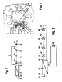
- FIG. 1 is a perspective view of the front of a device base of a suitable for the electrical and mechanical connection in a standard flush-mounted box flush-mounted LED light shown. It can be seen a support plate (support ring) 2 and an LED module 3 of the flush-mounted LED light 1, wherein the support plate 2 over a large area over the entire front surface of a hidden (not recognizable) device base extends and only a recess 22 for the passage of electrical Has connections between the device base and LED module, see connector 23 of the LED module. 3
- the LED module 3 has a printed circuit board 5 on which (at least) an LED illuminant 4, an adjustment device 7 for specifying a desired light intensity of the LED illuminant respectively the flush-mounted LED light and optionally a resistor 8, a transistor. 9 and an adjustable resistor 10 (potentiometer) are mounted. Furthermore, solder points 6 of the plug-in device 23 are outlined.
- the LED illuminant 4 may be in the form of separate (single) LEDs or in the form of so-called multi-chip LEDs and includes at least two independently switchable LEDs.
- the back of the support plate subsequent device base includes a converter 13 (power supply) including primary connection 14 for the connection of 230V power lines 15 and secondary terminal 16 for connecting the LED module having at least two LEDs 3.
- a converter 13 power supply
- a light intensity setting of the flush-mounted LED light is represented by a switch. It is the converter 13 (LED driver, power supply) to recognize, with a primary terminal 14 for connecting 230V power lines 15 and with a secondary terminal 16 for connecting at least one LED bulb 4, which as shown, for. B. from four series-connected LEDs 17, 18, 19, 20 is formed.
- the converter 13 LED driver, power supply
- the open-circuit and short-circuit proof converter 13 supplies a constant direct current, z. B. 350 mA.
- the switching device 7 for specifying a desired light intensity is formed in the embodiment shown in the form of a switch, such as slide switch or rotary switch, namely the first terminal of this switch is connected to the secondary terminal 16 and the second terminal of the switch is located at the common connection point of the two LEDs 19, 20. If the switch is closed, the LEDs 17, 18, 19 are bridged and only the LED 20 is lit, d. H. the light intensity of the flush-mounted LED light is reduced. If the switch is open, all LEDs 17, 18, 19, 20, d. H. the light intensity of the flush-mounted LED light is maximum.
- the setting device 7 can be designed to specify a desired light intensity in the form of a bistable reed contact, which changes the current switching state "open” - "closed” - “open”, etc. with each approach of a magnet.
- the advantage of this embodiment is that it is possible at a later date already installed flush-mounted LED light 1, without disassembly of individual components of the flush-mounted LED light 1 make a change in the light intensity, ie it is a very convenient , assembly-free operability / adjustability from the outside by magnet allows.
- the setting device 7 can be designed to specify a desired light intensity in the form of a switch controlled by a motion detector (PIR sensor), i. H. as soon as the motion detector detects a person, the full light intensity of the flush-mounted LED light 1 is switched on (all LEDs light up: Spotlight with high light intensity) and as soon as no person is detected by the motion detector, the diminished light intensity is switched on (only one LED lights up) : Orientation light with reduced light intensity).
- PIR sensor motion detector
- a light intensity setting of the flush-mounted LED light is represented by a potentiometer for controlling the current through the LEDs.
- a potentiometer for controlling the current through the LEDs.
- the converter 13 has a drive terminal 21, to which an adjustable resistor 10 (potentiometer) is connected for setting the current at the secondary terminal 16 constant DC current.
- an adjustable resistor 10 potentiometer
- a fixed resistor can be switched on / off via a switch.
- the switch by operating the switch, it is possible to set two different values for the output-side constant-direct current of the converter 13, thereby being able to specify two different values for the light intensity of the flush-mounted LED lamp 1. This control is particularly advantageous if the access to the individual LEDs is not possible or only one LED is used.
- a light intensity setting of the flush-mounted LED light is shown via a semiconductor element.
- the adjusting device 7 for specifying a desired light intensity is in the form of a controllable semiconductor element, in particular transistor 9 is formed.
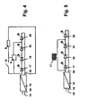
- the control circuit of the transistor 9 is located at the common connection point of the switch 12 with the resistor 8. As soon as the switch 12 is closed, the transistor 9 is "turned on”. As soon as the switch 12 is opened, the transistor 9 is also "switched off”.
- a light intensity setting of the flush-mounted LED light is represented by a jumper.
- the embodiment corresponds to in Fig. 2 explained embodiment, but as a setting device 7 for specifying a desired light intensity concretely a (j) jumper / wire bridge 11 is provided.
- the LEDs 17, 18, 19 are electrically bridged, ie only the LED 20 lights up and there is the case of a flush-mounted LED light 1 operated with reduced light intensity.
- the setting device 7 for specifying a desired light intensity in the form of a solder bridge (soldered wire bridge) may be formed.
- Fig. 6 is a light intensity setting of the flush-mounted LED light over bridgeable resistors for controlling the current through the LEDs shown.
- the configuration is the same as under Fig. 3
- two series-connected resistors 24 and 25 are connected in place of the adjustable resistor 10 to the drive terminal 21, wherein the resistor 25 can be bridged by means of a switch 26. By closing / opening the switch 26, two different current values for the LEDs can be specified.
Landscapes
- Circuit Arrangement For Electric Light Sources In General (AREA)
- Non-Portable Lighting Devices Or Systems Thereof (AREA)
- Arrangement Of Elements, Cooling, Sealing, Or The Like Of Lighting Devices (AREA)
Abstract
Description
- Die Erfindung betrifft eine Unterputz-LED-Leuchte für den Einbau in eine handelsübliche UP-Gerätedose (insbesondere nach DIN 49073).
- Aus der
DE 203 13 428 U1 ist eine aus einer Montageplatte, einer mit Leuchtdioden und gegebenenfalls weiteren elektronischen Bauteilen bestückten Leiterplatte mit Stromzuführungsleitungen, einer Lichtverteilungsscheibe und einem Blendrahmen mit einer Lichtaustrittsöffnung bestehende Leuchte bekannt. Die Stromzuführungsleitungen sind zu einer im Wesentlichen hinter der Leuchte angeordneten Anschlussdose geführt, in der ein an das Stromnetz anschließbarer Transformator angeordnet ist. Es können die Anschlussleitungen mehrerer Leuchten hinter einem Wandbelag (Fliesen, Fliesenspiegel) zu einer zentralen Anschlussstelle geführt sein, an der eine Niederspannungsquelle (Trafo) installiert ist. - Aus der
DE 10 2007 001 850 B3 ist ein Installationsschalter oder -taster mit Gerätesockel, Wippe und Beleuchtung bekannt, wobei ein Lichtleiter an der Rückseite der Wippe angeordnet ist und wobei im Gerätesockel ein Lampenhalter mit einer Lampe angeordnet ist, deren Licht in eine Lichteintrittsfläche des Lichtleiters strahlt. Die Wippe weist an ihrer bei montiertem Installationsschalter oder -taster vorzugsweise in Richtung Fußboden weisenden Seitenkante eine Lichtaustrittsöffnung auf, welche eine Lichtaustrittsfläche des Lichtleiters aufnimmt, so dass der unterhalb des montierten Installationsschalters oder -tasters befindliche Fußboden erhellt wird. Bei Ausführung als Installationsschalter mit zwei unterschiedlichen Stellungen der Wippe wird die Lampe lediglich in der Ausschalt-Stellung der Wippe eingeschaltet, während die Lampe in der Einschalt-Stellung der Wippe ausgeschaltet bleibt. Zwar strahlt die Lichtaustrittsöffnung vorzugsweise in Richtung Fußboden, alternativ kann der Installationsschalter oder -taster jedoch auch um 180° gedreht montiert werden, so dass die Lichtaustrittsöffnung in Richtung Decke strahlt, was bei einer sehr hellen, vorzugsweise weißen Decke zur Reflexion des abgestrahlten Lichts führt, wodurch die gewünschte Fußbodenbeleuchtung realisiert wird. - Allgemein sind bei Leuchten je nach Einsatzzweck und Einsatzort unterschiedliche Lichtintensitäten wünschenswert. Da bei einer LED-Leuchte ein Auswechseln des Leuchtmittels nicht in einfacher Art und Weise erfolgen kann, wäre es erforderlich, LED-Leuchten unterschiedlicher Lichtintensität herzustellen und zu bevorraten, um je nach Einsatzzweck und Einsatzort die richtige LED-Leuchte zur Verfügung stellen zu können. Dies stellt jedoch einen gewissen Aufwand dar.
- Der Erfindung liegt die Aufgabe zugrunde, eine Unterputz-LED-Leuchte anzugeben, welche universell für unterschiedliche Einsatzzwecke und Einsatzorte einsetzbar ist.
- Diese Aufgabe wird erfindungsgemäß gelöst durch eine Unterputz-LED-Leuchte für den elektrischen und mechanischen Anschluss an einer handelsüblichen UP-Gerätedose,
- mit einem Gerätesockel, welcher einen Konverter inklusive eines Primäranschlusses für den Anschluss von 230V-Netzleitungen und eines Sekundäranschlusses zum Anschluss eines LED-Moduls beinhaltet und
- mit einer Einstellvorrichtung zur Vorgabe einer gewünschten Lichtintensität, mit welcher entweder der dem LED-Modul zugeführte Strom einstellbar ist oder mittels der bei einem mindestens zwei LEDs aufweisenden LED-Modul mindestens eine der LEDs separat ein-/ausschaltbar respektive elektrisch überbrückbar ist.
- Die mit der Erfindung erzielbaren Vorteile bestehen insbesondere darin, dass ein-und dieselbe Unterputz-LED-Leuchte durch Umschaltung sowohl als Orientierungsleuchte mit relativ geringer Lichtintensität als auch als Strahler mit relativ hoher Lichtintensität verwendbar ist. Es wird eine Raumbeleuchtung durch LEDs aus der Unterputzdose heraus geschaffen, und zwar mit ein und derselben Unterputz-LED-Leuchte wahlweise vorgebbar als
- Funktionslicht mit voller Lichtintensität
- "Ambientelicht" mit reduzierter Lichtintensität
- Sekundärlicht mit reduzierter Lichtintensität.
- Die Unterputz-LED-Leuchte wird komplettiert durch eine Abdeckung des LED-Leuchtmittels als "Zentralscheibe" und einen Abdeckrahmen, so dass eine formschöne Einbindung / Integration in ein Installationsgeräte -Programm respektive Schalter-und Steckdosenprogramm sowie eine Kombination mit weiteren Geräten, beispielsweise Schaltern / Tastern / Dimmern / Steckdosen dieses Schalter- und Steckdosenprogramms möglich ist.
- Vorteilhafte Ausgestaltungen der Erfindung sind in den Unteransprüchen gekennzeichnet.
- Die Erfindung wird nachstehend an Hand der in der Zeichnung dargestellten Ausführungsbeispiele erläutert. Es zeigen:
- Fig. 1
- eine perspektivische Sicht auf die Frontseite eines Gerätesockels einer Unterputz-LED-Leuchte,
- Fig. 2
- eine Lichtintensitätseinstellung der Unterputz-LED-Leuchte über einen Schalter,
- Fig. 3
- eine Lichtintensitätseinstellung der Unterputz-LED-Leuchte über ein Potentiometer zur Regelung / Steuerung des Stromes durch die LEDs,
- Fig. 4
- eine Lichtintensitätseinstellung der Unterputz-LED-Leuchte über ein Halbleiterelement,
- Fig. 5
- eine Lichtintensitätseinstellung der Unterputz-LED-Leuchte über einen Jumper,
- Fig. 6
- eine Lichtintensitätseinstellung der Unterputz-LED-Leuchte über überbrückbare Widerstände zur Steuerung des Stromes durch die LEDs.
- In
Fig. 1 ist eine perspektivische Sicht auf die Frontseite eines Gerätesockels einer für den elektrischen und mechanischen Anschluss in einer handelsüblichen UP-Gerätedose geeigneten Unterputz-LED-Leuchte dargestellt. Es sind eine Tragplatte (Tragring) 2 und ein LED-Modul 3 der Unterputz-LED-Leuchte 1 zu erkennen, wobei sich die Tragplatte 2 großflächig über die gesamte Frontfläche eines verdeckten (nicht erkennbaren) Gerätesockels erstreckt und lediglich eine Ausnehmung 22 zum Durchgriff elektrischer Verbindungen zwischen Gerätesockel und LED-Modul aufweist, siehe Steckvorrichtung 23 des LED-Moduls 3. - Das LED-Modul 3 weist eine Leiterplatte 5 auf, auf welcher (mindestens) ein LED-Leuchtmittel 4, eine Einstellvorrichtung 7 zur Vorgabe einer gewünschten Lichtintensität des LED-Leuchtmittels respektive der Unterputz-LED-Leuchte sowie gegebenenfalls ein Widerstand 8, ein Transistor 9 und ein einstellbarer Widerstand 10 (Potentiometer) montiert sind. Ferner sind Lötpunkte 6 der Steckvorrichtung 23 skizziert. Das LED-Leuchtmittel 4 kann in Form separater (Einzel-) LEDs oder in Form sogenannter Multi-Chip-LEDs ausgebildet sein und beinhaltet mindestens zwei unabhängig voneinander schaltbare LEDs.
- Der sich rückseitig der Tragplatte anschließende Gerätesockel enthält einen Konverter 13 (Netzteil) inklusive Primäranschluss 14 für den Anschluss von 230V-Netzleitungen 15 und Sekundäranschluss 16 zum Anschluss des mindestens zwei LEDs aufweisenden LED-Moduls 3. Mit der Einstellvorrichtung 7 zur Vorgabe einer gewünschten Lichtintensität ist mindestens eine der LEDs separat ein-/ausschaltbar respektive elektrisch leitend überbrückbar.
- In
Fig. 2 ist eine Lichtintensitätseinstellung der Unterputz-LED-Leuchte über einen Schalter dargestellt. Es ist der Konverter 13 (LED-Treiber, Netzteil) zu erkennen, mit einem Primäranschluss 14 zum Anschluss von 230V-Netzleitungen 15 und mit einem Sekundäranschluss 16 für den Anschluss mindestens eines LED-Leuchtmittels 4, welches wie gezeigt z. B. aus vier in Serie geschaltete LEDs 17, 18, 19, 20 gebildet ist. - Der leerlauf- und kurzschlussfeste Konverter 13 liefert einen Konstant-Gleichstrom, z. B. 350 mA. Die Umschalteinrichtung 7 zur Vorgabe einer gewünschten Lichtintensität ist beim gezeigten Ausführungsbeispiel in Form eines Schalters, wie Schiebeschalter oder Drehschalter, ausgebildet, und zwar ist der erste Anschluss dieses Schalters mit dem Sekundäranschluss 16 verbunden und der zweite Anschluss des Schalters liegt am gemeinsamen Verbindungspunkt der beiden LEDs 19, 20. Ist der Schalter geschlossen, so werden die LEDs 17, 18, 19 überbrückt und lediglich die LED 20 leuchtet, d. h. die Lichtintensität der Unterputz-LED-Leuchte ist reduziert. Ist der Schalter offen, leuchten alle LEDs 17, 18, 19, 20, d. h. die Lichtintensität der Unterputz-LED-Leuchte ist maximal.
- Gemäß einer weiteren Ausführungsform kann die Einstellvorrichtung 7 zur Vorgabe einer gewünschten Lichtintensität in Form eines bistabilen Reedkontakts ausgebildet sein, welcher bei jeder Annäherung eines Magneten den aktuellen Schaltzustand "geöffnet" - "geschlossen" - "geöffnet" usw. wechselt. Der Vorteil bei dieser Ausführungsform besteht darin, dass es bei bereits montierter Unterputz-LED-Leuchte 1 zu einem späteren Zeitpunkt möglich ist, ohne Demontage einzelner Baukomponenten der Unterputz-LED-Leuchte 1 eine Änderung hinsichtlich der Lichtintensität vorzunehmen, d. h. es wird eine sehr bequeme, montagefreie Bedienbarkeit/Einstellbarkeit von außen per Magnet ermöglicht.
- Gemäß einer weiteren Ausführungsform kann die Einstellvorrichtung 7 zur Vorgabe einer gewünschten Lichtintensität in Form eines von einem Bewegungsmelder (PIR-Sensor) angesteuerten Schalters ausgebildet sein, d. h. sobald der Bewegungsmelder eine Person detektiert, wird die volle Lichtintensität der Unterputz-LED-Leuchte 1 eingeschaltet (alle LEDs leuchten: Strahler mit hoher Lichtintensität) und sobald mittels des Bewegungsmelders keine Person mehr erfasst wird, wird die verminderte Lichtintensität eingeschaltet (nur eine LED leuchtet: Orientierungslicht mit verringerter Lichtintensität).
- In
Fig. 3 ist eine Lichtintensitätseinstellung der Unterputz-LED-Leuchte über ein Potentiometer zur Regelung / Steuerung des Stromes durch die LEDs dargestellt. Am Sekundäranschluss 16 des Konverters 13 sind wiederum vier LEDs 17, 18, 19, 20 in Serie geschaltet. Der Konverter 13 weist einen Ansteueranschluss 21 auf, an welchen ein einstellbarer Widerstand 10 (Potentiometer) zur Einstellung des am Sekundäranschluss 16 anstehenden Konstant-Gleichstroms angeschlossen ist. Durch Betätigung des einstellbaren Widerstandes 10 ist der dem LED-Modul und damit den einzelnen LEDs zugeführte Strom zur Vorgabe einer gewünschten Lichtintensität veränderbar / einstellbar. Ferner kann durch Betätigung des einstellbaren Widerstandes 10 ein Feinabgleich der Lichtintensität erfolgen, um z. B. bei mehreren, benachbart angeordneten Unterputz-LED-Leuchten sicherzustellen, dass alle Unterputz-LED-Leuchten mit der gleichen Lichtintensität leuchten. - Bei einer hierzu vereinfachten Ausführungsform kann an Stelle des einstellbaren Widerstandes 10 (Potentiometer) ein fester Widerstand über einen Schalter ein-/ausgeschaltet werden. Bei dieser vereinfachten Ausführungsform ist es durch Betätigung des Schalters möglich, zwei unterschiedliche Werte für den ausgangsseitigen Konstant-Gleichstrom des Konverters 13 einzustellen, um hierdurch zwei unterschiedliche Werte für die Lichtintensität der Unterputz-LED-Leuchte 1 vorgeben zu können. Diese Ansteuerung ist besonders dann vorteilhaft, wenn der Zugang zu den einzelnen LEDs nicht möglich ist oder nur eine LED verwendet wird.
- In
Fig. 4 ist eine Lichtintensitätseinstellung der Unterputz-LED-Leuchte über ein Halbleiterelement dargestellt. Bei diesem Ausführungsbeispiel wird Rücksicht darauf genommen, dass Miniaturschalter oftmals nicht in der Lage sind, Gleichströme von 350 mA und mehr zu schalten respektive permanent zu führen. Dementsprechend ist ein Transistor 9 für die Überbrückung einer oder mehrerer LED(s) vorgesehen, d. h. die Einstellvorrichtung 7 zur Vorgabe einer gewünschten Lichtintensität ist in Form eines ansteuerbaren Halbleiterelements, insbesondere Transistors 9 ausgebildet. Die Serienschaltung eines Schalters 12 mit einem Widerstand 8 liegt am Sekundäranschluss 16 des Konverters 13. Der Ansteueranschluss des Transistors 9 liegt am gemeinsamen Verbindungspunkt des Schalters 12 mit dem Widerstand 8. Sobald der Schalter 12 geschlossen ist, wird auch der Transistor 9 "eingeschaltet". Sobald der Schalter 12 geöffnet wird, wird auch der Transistor 9 "ausgeschaltet". - In
Fig. 5 ist eine Lichtintensitätseinstellung der Unterputz-LED-Leuchte über einen Jumper dargestellt. Das Ausführungsbeispiel entspricht der inFig. 2 erläuterten Ausführungsform, wobei jedoch als Einstellvorrichtung 7 zur Vorgabe einer gewünschten Lichtintensität konkret ein(e) Jumper / Drahtbrücke 11 vorgesehen ist. Sobald der Jumper 11 mechanisch eingesetzt ist, werden die LEDs 17, 18, 19 elektrisch überbrückt, d. h. es leuchtet lediglich die LED 20 und es liegt der Fall einer mit reduzierter Lichtintensität betriebenen Unterputz-LED-Leuchte 1 vor. Sobald der Jumper 11 entfernt ist, leuchten alle vier LEDs 17 - 20 und es liegt der Fall einer mit maximaler Lichtintensität betriebenen Unterputz-LED-Leuchte 1 vor. In ähnlicher Weise kann die Einstellvorrichtung 7 zur Vorgabe einer gewünschten Lichtintensität auch in Form einer Lötbrücke (fest verlötete Drahtbrücke) ausgebildet sein. - In
Fig. 6 ist eine Lichtintensitätseinstellung der Unterputz-LED-Leuchte über überbrückbare Widerstände zur Steuerung des Stromes durch die LEDs dargestellt. Die Konfiguration entspricht derjenigen unterFig. 3 gezeigten Konfiguration, jedoch sind zwei in Serie geschaltete Widerstände 24 und 25 an Stelle des einstellbaren Widerstandes 10 an den Ansteueranschluss 21 geschaltet, wobei der Widerstand 25 mittels eines Schalters 26 überbrückt werden kann. Durch Schließen / Öffnen des Schalters 26 sind zwei unterschiedliche Stromwerte für die LEDs vorgebbar. -
- 1
- Unterputz-LED-Leuchte mit Gerätesockel (inklusive Konverter, Steuer-/Regeleinrichtung, Anschlusseinheit für 230V-Netzleitungen)
- 2
- Tragplatte (Tragring)
- 3
- LED-Modul
- 4
- LED-Leuchtmittel
- 5
- Leiterplatte
- 6
- Lötpunkte der Steckvorrichtung 23
- 7
- Einstellvorrichtung zur Vorgabe einer gewünschten Lichtintensität (Schalter, Schiebeschalter, Drehschalter, Jumper, Lötbrücke, Drahtbrücke, bistabiler Reedkontakt, Bewegungsmelder) zur Überbrückung von LEDs des LED-Leuchtmittels
- 8
- Widerstand
- 9
- Transistor
- 10
- einstellbarer Widerstand (Potentiometer)
- 11
- Jumper
- 12
- -
- 13
- Konverter (Netzteil, LED-Treiber, liefert Konstant-Gleichstrom am Ausgang, z. B. 350 mA)
- 14
- Primäranschluss
- 15
- 230V-Netzleitungen
- 16
- Sekundäranschluss
- 17
- LED
- 18
- LED
- 19
- LED
- 20
- LED
- 21
- Ansteueranschluss des Konverters
- 22
- Ausnehmung
- 23
- Steckvorrichtung
- 24
- Widerstand
- 25
- Widerstand
- 26
- Schalter
Claims (10)
- Unterputz-LED-Leuchte (1) für den elektrischen und mechanischen Anschluss in einer handelsüblichen UP-Gerätedose,- mit einem Gerätesockel, welcher einen Konverter (13) inklusive eines Primäranschlusses (14) für den Anschluss von 230V-Netzleitungen (15) und eines Sekundäranschlusses (16) zum Anschluss eines LED-Moduls (3) beinhaltet und- mit einer Einstellvorrichtung (7 -11) zur Vorgabe einer gewünschten Lichtintensität, mit welcher entweder der dem LED-Modul (3) zugeführte Strom einstellbar ist oder mittels der bei einem mindestens zwei LEDs (17 - 20) aufweisenden LED-Modul (3) mindestens eine der LEDs (17 - 20) separat ein-/ausschaltbar respektive elektrisch überbrückbar ist.
- Unterputz-LED-Leuchte nach Anspruch 1, dadurch gekennzeichnet, dass die Einstellvorrichtung (7) zur Vorgabe einer gewünschten Lichtintensität in Form eines Schalters, wie Schiebeschalter oder Drehschalter, ausgebildet ist.
- Unterputz-LED-Leuchte nach Anspruch 1, dadurch gekennzeichnet, dass die Einstellvorrichtung (7) zur Vorgabe einer gewünschten Lichtintensität in Form eines Jumpers / Drahtbrücke (11) ausgebildet ist.
- Unterputz-LED-Leuchte nach Anspruch 1, dadurch gekennzeichnet, dass die Einstellvorrichtung (7) zur Vorgabe einer gewünschten Lichtintensität in Form eines ansteuerbaren Halbleiterelements, insbesondere Transistors (9) ausgebildet ist.
- Unterputz-LED-Leuchte nach Anspruch 1, dadurch gekennzeichnet, dass die Einstellvorrichtung (7) zur Vorgabe einer gewünschten Lichtintensität in Form einer Lötbrücke ausgebildet ist.
- Unterputz-LED-Leuchte nach Anspruch 1, dadurch gekennzeichnet, dass die Einstellvorrichtung (7) zur Vorgabe einer gewünschten Lichtintensität in Form eines bistabilen Reedkontakts ausgebildet ist.
- Unterputz-LED-Leuchte nach Anspruch 1, dadurch gekennzeichnet, dass die Einstellvorrichtung (7) zur Vorgabe einer gewünschten Lichtintensität in Form eines von einem Bewegungsmelder angesteuerten Schalters ausgebildet ist.
- Unterputz-LED-Leuchte nach einem der vorstehenden Ansprüche, dadurch gekennzeichnet, dass der Konverter (13) einen Ansteueranschluss (21) aufweist, an welchen ein Widerstand (10, 24 + 25) zur Einstellung des am Sekundäranschluss (16) anstehenden Konstant-Gleichstroms angeschlossen ist.
- Unterputz-LED-Leuchte nach Anspruch 8, dadurch gekennzeichnet, dass der Widerstand (10) einstellbar ist.
- Unterputz-LED-Leuchte nach Anspruch 8, dadurch gekennzeichnet, dass ein Teil des Widerstands (24 + 25) mittels eines Schalters (26) überbrückbar ist.
Applications Claiming Priority (1)
| Application Number | Priority Date | Filing Date | Title |
|---|---|---|---|
| DE102010005504A DE102010005504A1 (de) | 2010-01-23 | 2010-01-23 | Unterputz-LED-Leuchte |
Publications (3)
| Publication Number | Publication Date |
|---|---|
| EP2348792A2 true EP2348792A2 (de) | 2011-07-27 |
| EP2348792A3 EP2348792A3 (de) | 2016-10-12 |
| EP2348792B1 EP2348792B1 (de) | 2021-05-12 |
Family
ID=43921044
Family Applications (1)
| Application Number | Title | Priority Date | Filing Date |
|---|---|---|---|
| EP10014724.8A Active EP2348792B1 (de) | 2010-01-23 | 2010-11-18 | Unterputz-LED-Leuchte |
Country Status (3)
| Country | Link |
|---|---|
| EP (1) | EP2348792B1 (de) |
| CN (1) | CN102155701B (de) |
| DE (1) | DE102010005504A1 (de) |
Cited By (2)
| Publication number | Priority date | Publication date | Assignee | Title |
|---|---|---|---|---|
| CN102367933A (zh) * | 2011-10-20 | 2012-03-07 | 东营泰克拓普光电科技有限公司 | 一种桥梁专用路灯 |
| EP3562269A1 (de) * | 2018-04-27 | 2019-10-30 | Valeo Iluminacion | Elektronische anordnung, beleuchtungsvorrichtung und verfahren zur herstellung einer beleuchtungsvorrichtung |
Families Citing this family (4)
| Publication number | Priority date | Publication date | Assignee | Title |
|---|---|---|---|---|
| DE102011008507B3 (de) * | 2011-01-13 | 2012-04-26 | Abb Ag | Unterputz-LED-Leuchte |
| DE102015211454A1 (de) | 2015-06-22 | 2016-12-22 | Tridonic Gmbh & Co Kg | Sensorspeisung mit einem Konstantstrom-Konverter für Leuchtmittel |
| DE102015219367B4 (de) | 2015-10-07 | 2022-07-14 | H4X E.U. | Led-leuchte mit steuerschaltung |
| DE102016210448B4 (de) * | 2016-06-13 | 2022-11-24 | H4X E.U. | LED-Leuchte mit LED-Leuchtmitteln unterschiedlicher Farbtemperatur |
Citations (2)
| Publication number | Priority date | Publication date | Assignee | Title |
|---|---|---|---|---|
| DE20313428U1 (de) | 2003-08-29 | 2003-11-27 | Hoffmeister Leuchten Gmbh | Elektrische Leuchte |
| DE102007001850B3 (de) | 2007-01-12 | 2008-02-14 | Abb Patent Gmbh | Installationsschalter oder -taster mit Beleuchtung und Baukastensystem zur Bildung eines Installationsschalters oder -tasters mit Beleuchtung |
Family Cites Families (12)
| Publication number | Priority date | Publication date | Assignee | Title |
|---|---|---|---|---|
| JPH11109918A (ja) * | 1997-10-03 | 1999-04-23 | Futaba Corp | 有機elディスプレイ装置 |
| DE29904174U1 (de) * | 1999-03-09 | 2000-07-20 | Merten GmbH & Co. KG, 51674 Wiehl | Installationsschalter für die Gebäudeinstallation |
| DE19919080A1 (de) * | 1999-04-27 | 2000-11-02 | Insta Elektro Gmbh & Co Kg | Beleuchtungseinrichtung |
| JP3424617B2 (ja) * | 1999-09-10 | 2003-07-07 | 株式会社デンソー | 車載用表示器の駆動装置 |
| EP1493621B1 (de) * | 2003-07-03 | 2008-12-10 | Eltam Ein Hashofet | Beleuchtungsvorrichtung |
| CN1602132A (zh) * | 2003-09-24 | 2005-03-30 | 皇家飞利浦电子股份有限公司 | 一种控制发光装置的系统与方法 |
| US7994732B2 (en) * | 2006-11-03 | 2011-08-09 | Zulch Laboratories, Inc. | Intensity changing with reduced flicker for digitally-controlled lighting |
| WO2008129485A1 (en) * | 2007-04-24 | 2008-10-30 | Koninklijke Philips Electronics N. V. | User interface for multiple light control dimensions |
| RU2475674C2 (ru) * | 2007-05-02 | 2013-02-20 | Конинклейке Филипс Электроникс Н.В. | Твердотельное устройство освещения |
| DE102008017653B4 (de) * | 2008-04-04 | 2010-02-25 | EVN Elektro-Vertrieb-Nürnberg GmbH | Leuchtvorrichtung |
| CN101616521B (zh) * | 2008-06-23 | 2012-11-21 | 台达电子工业股份有限公司 | 可调光的发光二极管驱动电路 |
| DE102009022401A1 (de) * | 2009-01-21 | 2010-07-22 | Abb Ag | Leuchte, insbesondere Wandleuchte |
-
2010
- 2010-01-23 DE DE102010005504A patent/DE102010005504A1/de not_active Ceased
- 2010-11-18 EP EP10014724.8A patent/EP2348792B1/de active Active
-
2011
- 2011-01-14 CN CN201110022288.9A patent/CN102155701B/zh not_active Expired - Fee Related
Patent Citations (2)
| Publication number | Priority date | Publication date | Assignee | Title |
|---|---|---|---|---|
| DE20313428U1 (de) | 2003-08-29 | 2003-11-27 | Hoffmeister Leuchten Gmbh | Elektrische Leuchte |
| DE102007001850B3 (de) | 2007-01-12 | 2008-02-14 | Abb Patent Gmbh | Installationsschalter oder -taster mit Beleuchtung und Baukastensystem zur Bildung eines Installationsschalters oder -tasters mit Beleuchtung |
Cited By (5)
| Publication number | Priority date | Publication date | Assignee | Title |
|---|---|---|---|---|
| CN102367933A (zh) * | 2011-10-20 | 2012-03-07 | 东营泰克拓普光电科技有限公司 | 一种桥梁专用路灯 |
| EP3562269A1 (de) * | 2018-04-27 | 2019-10-30 | Valeo Iluminacion | Elektronische anordnung, beleuchtungsvorrichtung und verfahren zur herstellung einer beleuchtungsvorrichtung |
| WO2019207135A1 (en) * | 2018-04-27 | 2019-10-31 | Valeo Iluminacion | Electronic assembly, lighting device and method for manufacturing a lighting device |
| CN112005045A (zh) * | 2018-04-27 | 2020-11-27 | 法雷奥照明公司 | 电子组件、发光装置以及用于制造发光装置的方法 |
| US11178736B2 (en) | 2018-04-27 | 2021-11-16 | Valeo Vision | Electronic assembly, lighting device and method for manufacturing a lighting device |
Also Published As
| Publication number | Publication date |
|---|---|
| DE102010005504A1 (de) | 2011-07-28 |
| EP2348792A3 (de) | 2016-10-12 |
| EP2348792B1 (de) | 2021-05-12 |
| CN102155701B (zh) | 2015-05-13 |
| HK1156682A1 (en) | 2012-06-15 |
| CN102155701A (zh) | 2011-08-17 |
Similar Documents
| Publication | Publication Date | Title |
|---|---|---|
| EP2348522B1 (de) | Installationsschalter oder -taster mit einer Wippe mit einem Lichtauslass für eine Beleuchtung | |
| DE102009016778B4 (de) | Unterputz-LED-Leuchte | |
| DE102005060971B4 (de) | Hochleistungs-LED-Farbleuchte mit Infrarot-Fernbedienungsfunktion | |
| EP2211084B1 (de) | Leuchte, insbesondere Wandleuchte | |
| EP2348249B1 (de) | Unterputz-LED-Leuchte | |
| EP2348792B1 (de) | Unterputz-LED-Leuchte | |
| EP3534066B1 (de) | Leuchte, gehäusekomponente für eine leuchte, sowie verfahren zur herstellung einer leuchte | |
| EP2151899A2 (de) | Lichtbandsystem | |
| DE102016120256A1 (de) | Beleuchtungsvorrichtung mit variabler lichtverteilung | |
| EP2363634B1 (de) | Unterputz-LED-Leuchte, insbesondere Deckenleuchte | |
| DE10113240A1 (de) | Multifunktionsleuchte | |
| DE102008064453A1 (de) | Elektrisches Installationsgerät | |
| DE10329358B4 (de) | Elektrische/elektronische Einrichtung | |
| DE102011008507B3 (de) | Unterputz-LED-Leuchte | |
| EP2150749B1 (de) | Beleuchtungsvorrichtung mit einer an einer oberfläche eines objekts anbringbaren schienenvorrichtung | |
| EP2838171B1 (de) | Elektrisches Installationsgerät mit Beleuchtungselement | |
| DE20101295U1 (de) | Beleuchtungseinrichtung zum Betrieb an einem Wechselstromnetz | |
| DE29711379U1 (de) | Beleuchtungsanlage mit Dimmer | |
| DE102008017653B4 (de) | Leuchtvorrichtung | |
| DE102010005505B4 (de) | Unterputz-LED-Leuchte mit Tragplatte | |
| DE202012102609U9 (de) | Steuersystem für lichterzeugende Halbleiterbauteile | |
| EP0091001B1 (de) | Zentral an einem Leuchtenträger angeordneter Leuchtenkörper für die Anbringung von mehreren helligkeitsverstellbaren Lichtquellen | |
| DE102011080397A1 (de) | Dunstabzugshaubenhalterung und Dunstabzugssystem | |
| EP3527885B1 (de) | Anordnung umfassend ein elektrisches/elektronisches installationsgerät und eine elektrische leuchte | |
| EP3234459A1 (de) | Modulare beleuchtungseinrichtung |
Legal Events
| Date | Code | Title | Description |
|---|---|---|---|
| PUAI | Public reference made under article 153(3) epc to a published international application that has entered the european phase |
Free format text: ORIGINAL CODE: 0009012 |
|
| AK | Designated contracting states |
Kind code of ref document: A2 Designated state(s): AL AT BE BG CH CY CZ DE DK EE ES FI FR GB GR HR HU IE IS IT LI LT LU LV MC MK MT NL NO PL PT RO RS SE SI SK SM TR |
|
| AX | Request for extension of the european patent |
Extension state: BA ME |
|
| PUAL | Search report despatched |
Free format text: ORIGINAL CODE: 0009013 |
|
| AK | Designated contracting states |
Kind code of ref document: A3 Designated state(s): AL AT BE BG CH CY CZ DE DK EE ES FI FR GB GR HR HU IE IS IT LI LT LU LV MC MK MT NL NO PL PT RO RS SE SI SK SM TR |
|
| AX | Request for extension of the european patent |
Extension state: BA ME |
|
| RIC1 | Information provided on ipc code assigned before grant |
Ipc: H05B 33/08 20060101AFI20160906BHEP |
|
| STAA | Information on the status of an ep patent application or granted ep patent |
Free format text: STATUS: REQUEST FOR EXAMINATION WAS MADE |
|
| 17P | Request for examination filed |
Effective date: 20161114 |
|
| STAA | Information on the status of an ep patent application or granted ep patent |
Free format text: STATUS: EXAMINATION IS IN PROGRESS |
|
| 17Q | First examination report despatched |
Effective date: 20190531 |
|
| RAP1 | Party data changed (applicant data changed or rights of an application transferred) |
Owner name: ABB SCHWEIZ AG |
|
| REG | Reference to a national code |
Ref country code: DE Ref legal event code: R079 Ref document number: 502010016908 Country of ref document: DE Free format text: PREVIOUS MAIN CLASS: H05B0033080000 Ipc: H05B0045000000 |
|
| GRAP | Despatch of communication of intention to grant a patent |
Free format text: ORIGINAL CODE: EPIDOSNIGR1 |
|
| STAA | Information on the status of an ep patent application or granted ep patent |
Free format text: STATUS: GRANT OF PATENT IS INTENDED |
|
| RIC1 | Information provided on ipc code assigned before grant |
Ipc: H05B 45/00 20200101AFI20201109BHEP Ipc: H02G 3/12 20060101ALI20201109BHEP Ipc: H05B 45/37 20200101ALI20201109BHEP Ipc: F21S 8/02 20060101ALI20201109BHEP |
|
| INTG | Intention to grant announced |
Effective date: 20201203 |
|
| GRAS | Grant fee paid |
Free format text: ORIGINAL CODE: EPIDOSNIGR3 |
|
| GRAA | (expected) grant |
Free format text: ORIGINAL CODE: 0009210 |
|
| STAA | Information on the status of an ep patent application or granted ep patent |
Free format text: STATUS: THE PATENT HAS BEEN GRANTED |
|
| AK | Designated contracting states |
Kind code of ref document: B1 Designated state(s): AL AT BE BG CH CY CZ DE DK EE ES FI FR GB GR HR HU IE IS IT LI LT LU LV MC MK MT NL NO PL PT RO RS SE SI SK SM TR |
|
| REG | Reference to a national code |
Ref country code: GB Ref legal event code: FG4D Free format text: NOT ENGLISH |
|
| REG | Reference to a national code |
Ref country code: CH Ref legal event code: EP |
|
| REG | Reference to a national code |
Ref country code: DE Ref legal event code: R096 Ref document number: 502010016908 Country of ref document: DE |
|
| REG | Reference to a national code |
Ref country code: IE Ref legal event code: FG4D Free format text: LANGUAGE OF EP DOCUMENT: GERMAN |
|
| REG | Reference to a national code |
Ref country code: AT Ref legal event code: REF Ref document number: 1393052 Country of ref document: AT Kind code of ref document: T Effective date: 20210615 |
|
| REG | Reference to a national code |
Ref country code: NL Ref legal event code: FP |
|
| REG | Reference to a national code |
Ref country code: LT Ref legal event code: MG9D |
|
| PG25 | Lapsed in a contracting state [announced via postgrant information from national office to epo] |
Ref country code: LT Free format text: LAPSE BECAUSE OF FAILURE TO SUBMIT A TRANSLATION OF THE DESCRIPTION OR TO PAY THE FEE WITHIN THE PRESCRIBED TIME-LIMIT Effective date: 20210512 Ref country code: FI Free format text: LAPSE BECAUSE OF FAILURE TO SUBMIT A TRANSLATION OF THE DESCRIPTION OR TO PAY THE FEE WITHIN THE PRESCRIBED TIME-LIMIT Effective date: 20210512 Ref country code: BG Free format text: LAPSE BECAUSE OF FAILURE TO SUBMIT A TRANSLATION OF THE DESCRIPTION OR TO PAY THE FEE WITHIN THE PRESCRIBED TIME-LIMIT Effective date: 20210812 Ref country code: HR Free format text: LAPSE BECAUSE OF FAILURE TO SUBMIT A TRANSLATION OF THE DESCRIPTION OR TO PAY THE FEE WITHIN THE PRESCRIBED TIME-LIMIT Effective date: 20210512 |
|
| PG25 | Lapsed in a contracting state [announced via postgrant information from national office to epo] |
Ref country code: GR Free format text: LAPSE BECAUSE OF FAILURE TO SUBMIT A TRANSLATION OF THE DESCRIPTION OR TO PAY THE FEE WITHIN THE PRESCRIBED TIME-LIMIT Effective date: 20210813 Ref country code: IS Free format text: LAPSE BECAUSE OF FAILURE TO SUBMIT A TRANSLATION OF THE DESCRIPTION OR TO PAY THE FEE WITHIN THE PRESCRIBED TIME-LIMIT Effective date: 20210912 Ref country code: LV Free format text: LAPSE BECAUSE OF FAILURE TO SUBMIT A TRANSLATION OF THE DESCRIPTION OR TO PAY THE FEE WITHIN THE PRESCRIBED TIME-LIMIT Effective date: 20210512 Ref country code: RS Free format text: LAPSE BECAUSE OF FAILURE TO SUBMIT A TRANSLATION OF THE DESCRIPTION OR TO PAY THE FEE WITHIN THE PRESCRIBED TIME-LIMIT Effective date: 20210512 Ref country code: SE Free format text: LAPSE BECAUSE OF FAILURE TO SUBMIT A TRANSLATION OF THE DESCRIPTION OR TO PAY THE FEE WITHIN THE PRESCRIBED TIME-LIMIT Effective date: 20210512 Ref country code: NO Free format text: LAPSE BECAUSE OF FAILURE TO SUBMIT A TRANSLATION OF THE DESCRIPTION OR TO PAY THE FEE WITHIN THE PRESCRIBED TIME-LIMIT Effective date: 20210812 Ref country code: PT Free format text: LAPSE BECAUSE OF FAILURE TO SUBMIT A TRANSLATION OF THE DESCRIPTION OR TO PAY THE FEE WITHIN THE PRESCRIBED TIME-LIMIT Effective date: 20210913 Ref country code: PL Free format text: LAPSE BECAUSE OF FAILURE TO SUBMIT A TRANSLATION OF THE DESCRIPTION OR TO PAY THE FEE WITHIN THE PRESCRIBED TIME-LIMIT Effective date: 20210512 Ref country code: ES Free format text: LAPSE BECAUSE OF FAILURE TO SUBMIT A TRANSLATION OF THE DESCRIPTION OR TO PAY THE FEE WITHIN THE PRESCRIBED TIME-LIMIT Effective date: 20210512 |
|
| PG25 | Lapsed in a contracting state [announced via postgrant information from national office to epo] |
Ref country code: SK Free format text: LAPSE BECAUSE OF FAILURE TO SUBMIT A TRANSLATION OF THE DESCRIPTION OR TO PAY THE FEE WITHIN THE PRESCRIBED TIME-LIMIT Effective date: 20210512 Ref country code: SM Free format text: LAPSE BECAUSE OF FAILURE TO SUBMIT A TRANSLATION OF THE DESCRIPTION OR TO PAY THE FEE WITHIN THE PRESCRIBED TIME-LIMIT Effective date: 20210512 Ref country code: CZ Free format text: LAPSE BECAUSE OF FAILURE TO SUBMIT A TRANSLATION OF THE DESCRIPTION OR TO PAY THE FEE WITHIN THE PRESCRIBED TIME-LIMIT Effective date: 20210512 Ref country code: DK Free format text: LAPSE BECAUSE OF FAILURE TO SUBMIT A TRANSLATION OF THE DESCRIPTION OR TO PAY THE FEE WITHIN THE PRESCRIBED TIME-LIMIT Effective date: 20210512 Ref country code: EE Free format text: LAPSE BECAUSE OF FAILURE TO SUBMIT A TRANSLATION OF THE DESCRIPTION OR TO PAY THE FEE WITHIN THE PRESCRIBED TIME-LIMIT Effective date: 20210512 Ref country code: RO Free format text: LAPSE BECAUSE OF FAILURE TO SUBMIT A TRANSLATION OF THE DESCRIPTION OR TO PAY THE FEE WITHIN THE PRESCRIBED TIME-LIMIT Effective date: 20210512 |
|
| REG | Reference to a national code |
Ref country code: DE Ref legal event code: R097 Ref document number: 502010016908 Country of ref document: DE |
|
| PLBE | No opposition filed within time limit |
Free format text: ORIGINAL CODE: 0009261 |
|
| STAA | Information on the status of an ep patent application or granted ep patent |
Free format text: STATUS: NO OPPOSITION FILED WITHIN TIME LIMIT |
|
| 26N | No opposition filed |
Effective date: 20220215 |
|
| PG25 | Lapsed in a contracting state [announced via postgrant information from national office to epo] |
Ref country code: IS Free format text: LAPSE BECAUSE OF FAILURE TO SUBMIT A TRANSLATION OF THE DESCRIPTION OR TO PAY THE FEE WITHIN THE PRESCRIBED TIME-LIMIT Effective date: 20210912 Ref country code: AL Free format text: LAPSE BECAUSE OF FAILURE TO SUBMIT A TRANSLATION OF THE DESCRIPTION OR TO PAY THE FEE WITHIN THE PRESCRIBED TIME-LIMIT Effective date: 20210512 |
|
| PG25 | Lapsed in a contracting state [announced via postgrant information from national office to epo] |
Ref country code: MC Free format text: LAPSE BECAUSE OF FAILURE TO SUBMIT A TRANSLATION OF THE DESCRIPTION OR TO PAY THE FEE WITHIN THE PRESCRIBED TIME-LIMIT Effective date: 20210512 |
|
| REG | Reference to a national code |
Ref country code: CH Ref legal event code: PL |
|
| GBPC | Gb: european patent ceased through non-payment of renewal fee |
Effective date: 20211118 |
|
| PG25 | Lapsed in a contracting state [announced via postgrant information from national office to epo] |
Ref country code: LU Free format text: LAPSE BECAUSE OF NON-PAYMENT OF DUE FEES Effective date: 20211118 Ref country code: IT Free format text: LAPSE BECAUSE OF FAILURE TO SUBMIT A TRANSLATION OF THE DESCRIPTION OR TO PAY THE FEE WITHIN THE PRESCRIBED TIME-LIMIT Effective date: 20210512 Ref country code: BE Free format text: LAPSE BECAUSE OF NON-PAYMENT OF DUE FEES Effective date: 20211130 |
|
| REG | Reference to a national code |
Ref country code: BE Ref legal event code: MM Effective date: 20211130 |
|
| PG25 | Lapsed in a contracting state [announced via postgrant information from national office to epo] |
Ref country code: IE Free format text: LAPSE BECAUSE OF NON-PAYMENT OF DUE FEES Effective date: 20211118 Ref country code: GB Free format text: LAPSE BECAUSE OF NON-PAYMENT OF DUE FEES Effective date: 20211118 |
|
| PG25 | Lapsed in a contracting state [announced via postgrant information from national office to epo] |
Ref country code: FR Free format text: LAPSE BECAUSE OF NON-PAYMENT OF DUE FEES Effective date: 20211130 |
|
| PG25 | Lapsed in a contracting state [announced via postgrant information from national office to epo] |
Ref country code: HU Free format text: LAPSE BECAUSE OF FAILURE TO SUBMIT A TRANSLATION OF THE DESCRIPTION OR TO PAY THE FEE WITHIN THE PRESCRIBED TIME-LIMIT; INVALID AB INITIO Effective date: 20101118 Ref country code: CY Free format text: LAPSE BECAUSE OF FAILURE TO SUBMIT A TRANSLATION OF THE DESCRIPTION OR TO PAY THE FEE WITHIN THE PRESCRIBED TIME-LIMIT Effective date: 20210512 |
|
| PG25 | Lapsed in a contracting state [announced via postgrant information from national office to epo] |
Ref country code: LI Free format text: LAPSE BECAUSE OF NON-PAYMENT OF DUE FEES Effective date: 20220701 Ref country code: CH Free format text: LAPSE BECAUSE OF NON-PAYMENT OF DUE FEES Effective date: 20220701 |
|
| PG25 | Lapsed in a contracting state [announced via postgrant information from national office to epo] |
Ref country code: MK Free format text: LAPSE BECAUSE OF FAILURE TO SUBMIT A TRANSLATION OF THE DESCRIPTION OR TO PAY THE FEE WITHIN THE PRESCRIBED TIME-LIMIT Effective date: 20210512 |
|
| PG25 | Lapsed in a contracting state [announced via postgrant information from national office to epo] |
Ref country code: TR Free format text: LAPSE BECAUSE OF FAILURE TO SUBMIT A TRANSLATION OF THE DESCRIPTION OR TO PAY THE FEE WITHIN THE PRESCRIBED TIME-LIMIT Effective date: 20210512 |
|
| PG25 | Lapsed in a contracting state [announced via postgrant information from national office to epo] |
Ref country code: MT Free format text: LAPSE BECAUSE OF FAILURE TO SUBMIT A TRANSLATION OF THE DESCRIPTION OR TO PAY THE FEE WITHIN THE PRESCRIBED TIME-LIMIT Effective date: 20210512 |
|
| PGFP | Annual fee paid to national office [announced via postgrant information from national office to epo] |
Ref country code: NL Payment date: 20251119 Year of fee payment: 16 |
|
| PGFP | Annual fee paid to national office [announced via postgrant information from national office to epo] |
Ref country code: DE Payment date: 20251119 Year of fee payment: 16 |
|
| PGFP | Annual fee paid to national office [announced via postgrant information from national office to epo] |
Ref country code: AT Payment date: 20251120 Year of fee payment: 16 |