EP2349509B1 - Fixation pour planche de glisse sur neige et autres planches de sport - Google Patents
Fixation pour planche de glisse sur neige et autres planches de sport Download PDFInfo
- Publication number
- EP2349509B1 EP2349509B1 EP10813095.6A EP10813095A EP2349509B1 EP 2349509 B1 EP2349509 B1 EP 2349509B1 EP 10813095 A EP10813095 A EP 10813095A EP 2349509 B1 EP2349509 B1 EP 2349509B1
- Authority
- EP
- European Patent Office
- Prior art keywords
- base
- binding
- board
- board base
- snowboard
- Prior art date
- Legal status (The legal status is an assumption and is not a legal conclusion. Google has not performed a legal analysis and makes no representation as to the accuracy of the status listed.)
- Active
Links
- 230000027455 binding Effects 0.000 title claims description 216
- 238000009739 binding Methods 0.000 title claims description 216
- 210000002683 foot Anatomy 0.000 description 25
- 230000007246 mechanism Effects 0.000 description 18
- 210000003371 toe Anatomy 0.000 description 13
- 239000000463 material Substances 0.000 description 7
- XLYOFNOQVPJJNP-UHFFFAOYSA-N water Substances O XLYOFNOQVPJJNP-UHFFFAOYSA-N 0.000 description 5
- PXHVJJICTQNCMI-UHFFFAOYSA-N Nickel Chemical compound [Ni] PXHVJJICTQNCMI-UHFFFAOYSA-N 0.000 description 4
- 230000005291 magnetic effect Effects 0.000 description 4
- 239000004033 plastic Substances 0.000 description 4
- 238000010276 construction Methods 0.000 description 2
- 230000000694 effects Effects 0.000 description 2
- 239000003302 ferromagnetic material Substances 0.000 description 2
- 229910052751 metal Inorganic materials 0.000 description 2
- 239000002184 metal Substances 0.000 description 2
- 238000000034 method Methods 0.000 description 2
- 238000012986 modification Methods 0.000 description 2
- 230000004048 modification Effects 0.000 description 2
- 238000003032 molecular docking Methods 0.000 description 2
- 229910052759 nickel Inorganic materials 0.000 description 2
- 229920000049 Carbon (fiber) Polymers 0.000 description 1
- 229910052779 Neodymium Inorganic materials 0.000 description 1
- 239000004677 Nylon Substances 0.000 description 1
- 210000001361 achilles tendon Anatomy 0.000 description 1
- 230000009471 action Effects 0.000 description 1
- 230000004075 alteration Effects 0.000 description 1
- 229910052782 aluminium Inorganic materials 0.000 description 1
- XAGFODPZIPBFFR-UHFFFAOYSA-N aluminium Chemical compound [Al] XAGFODPZIPBFFR-UHFFFAOYSA-N 0.000 description 1
- 230000000712 assembly Effects 0.000 description 1
- 238000000429 assembly Methods 0.000 description 1
- 239000004917 carbon fiber Substances 0.000 description 1
- 239000011521 glass Substances 0.000 description 1
- 230000005484 gravity Effects 0.000 description 1
- 238000007373 indentation Methods 0.000 description 1
- 230000003993 interaction Effects 0.000 description 1
- 238000004519 manufacturing process Methods 0.000 description 1
- 150000002739 metals Chemical class 0.000 description 1
- VNWKTOKETHGBQD-UHFFFAOYSA-N methane Chemical compound C VNWKTOKETHGBQD-UHFFFAOYSA-N 0.000 description 1
- QEFYFXOXNSNQGX-UHFFFAOYSA-N neodymium atom Chemical compound [Nd] QEFYFXOXNSNQGX-UHFFFAOYSA-N 0.000 description 1
- 229920001778 nylon Polymers 0.000 description 1
- 239000004417 polycarbonate Substances 0.000 description 1
- 229920000515 polycarbonate Polymers 0.000 description 1
- 229910052761 rare earth metal Inorganic materials 0.000 description 1
- 150000002910 rare earth metals Chemical class 0.000 description 1
- 238000000926 separation method Methods 0.000 description 1
- 239000007787 solid Substances 0.000 description 1
- 230000003319 supportive effect Effects 0.000 description 1
- 229920001169 thermoplastic Polymers 0.000 description 1
- 239000004416 thermosoftening plastic Substances 0.000 description 1
Images










Classifications
-
- A—HUMAN NECESSITIES
- A63—SPORTS; GAMES; AMUSEMENTS
- A63C—SKATES; SKIS; ROLLER SKATES; DESIGN OR LAYOUT OF COURTS, RINKS OR THE LIKE
- A63C10/00—Snowboard bindings
-
- A—HUMAN NECESSITIES
- A63—SPORTS; GAMES; AMUSEMENTS
- A63C—SKATES; SKIS; ROLLER SKATES; DESIGN OR LAYOUT OF COURTS, RINKS OR THE LIKE
- A63C10/00—Snowboard bindings
- A63C10/02—Snowboard bindings characterised by details of the shoe holders
-
- A—HUMAN NECESSITIES
- A63—SPORTS; GAMES; AMUSEMENTS
- A63C—SKATES; SKIS; ROLLER SKATES; DESIGN OR LAYOUT OF COURTS, RINKS OR THE LIKE
- A63C10/00—Snowboard bindings
- A63C10/14—Interfaces, e.g. in the shape of a plate
- A63C10/145—Interfaces, e.g. in the shape of a plate between two superimposed binding systems, e.g. cradle
-
- A—HUMAN NECESSITIES
- A63—SPORTS; GAMES; AMUSEMENTS
- A63C—SKATES; SKIS; ROLLER SKATES; DESIGN OR LAYOUT OF COURTS, RINKS OR THE LIKE
- A63C9/00—Ski bindings
- A63C9/08—Ski bindings yieldable or self-releasing in the event of an accident, i.e. safety bindings
- A63C9/0802—Ski bindings yieldable or self-releasing in the event of an accident, i.e. safety bindings other than mechanically controlled, e.g. electric, electronic, hydraulic, pneumatic, magnetic, pyrotechnic devices; Remote control
-
- A—HUMAN NECESSITIES
- A63—SPORTS; GAMES; AMUSEMENTS
- A63C—SKATES; SKIS; ROLLER SKATES; DESIGN OR LAYOUT OF COURTS, RINKS OR THE LIKE
- A63C10/00—Snowboard bindings
- A63C10/02—Snowboard bindings characterised by details of the shoe holders
- A63C10/04—Shoe holders for passing over the shoe
- A63C10/06—Straps therefor, e.g. adjustable straps
-
- A—HUMAN NECESSITIES
- A63—SPORTS; GAMES; AMUSEMENTS
- A63C—SKATES; SKIS; ROLLER SKATES; DESIGN OR LAYOUT OF COURTS, RINKS OR THE LIKE
- A63C10/00—Snowboard bindings
- A63C10/16—Systems for adjusting the direction or position of the bindings
- A63C10/18—Systems for adjusting the direction or position of the bindings about a vertical rotation axis relative to the board
-
- A—HUMAN NECESSITIES
- A63—SPORTS; GAMES; AMUSEMENTS
- A63C—SKATES; SKIS; ROLLER SKATES; DESIGN OR LAYOUT OF COURTS, RINKS OR THE LIKE
- A63C10/00—Snowboard bindings
- A63C10/24—Calf or heel supports, e.g. adjustable high back or heel loops
Definitions
- bindings When riding a snowboard, each of the user's boots is secured to the snowboard, e.g., with an apparatus called a "binding."
- the bindings keep the user and board from separating during the ride down the slope. Bindings are also commonly configured to transfer forces from the user to the snowboard, allowing the user to control the snowboard during the ride.
- Bindings are also used for other board sports such as wakeboarding and kiteboarding and this invention relates to such other board sports.
- a strap-in binding may be designed to receive a boot, such as, for example, the type of boot that may be referred to in the art as a "soft boot.”
- a strap-in binding commonly incorporates one or more adjustable straps, which, when tightened, push the user's boot against the relatively rigid interior surfaces of the binding. The pressure of the straps and the interior surfaces hold the boot in the binding while the snowboard is in use and help the user to control the snowboard.
- a step-in binding may incorporate a relatively flat base that includes a mechanism that connects to hinges, fixtures, and/or other mechanisms on the bottom of the user's boot.
- a boot for use with a step-in binding is typically more rigid and sturdy than one typically used with a strap-in binding, and the rigid structures of the boot may transmit forces exerted by the user to the board, helping the user to control it.
- the construction that makes a boot suitable for use with a step-in binding may also make the boot heavier than a soft boot, however, as may the hardware built into the boot that is needed to secure the boot to the snowboard.
- Step-in bindings commonly entail using boots that may be heavier and stiffer than the soft boots that may typically be used with a strap-in binding.
- the weight and rigidity may make such boots less comfortable to wear than soft boots, and experienced snowboard users may feel that the weight and rigidity compromise the user's control of the snowboard during a ride.
- US 5035443 shows a step-in binding combining a soft boot and straps with an engagement mechanism as recited in the preamble of claim 1.
- Bindings are used for other board sports, such as wakeboarding and kiteboarding. Bindings or mechanisms connecting the foot to the board may usefully employ the benefits of this invention.
- Embodiments of the invention comprise a snowboard binding that comprises two main cooperating parts or assemblies.
- One part which may be referred to as a "board base” may be secured permanently to the snowboard.
- the other part which may be referred to as a “binding base” may be secured to a user's soft boot, e.g., in a manner similar to that of a strap-in binding.
- the board base and the binding base may be detached from one another and may also be securely reattached to each other so that the user can ride the snowboard.
- the binding base and the board base may be configured to help a user to join the bases without use of the hands.
- the user may wear a soft boot secured in a binding base and may, by moving the leg and/or foot, align the binding base with the board base, allowing the bases to be docked together.
- the user may then, by rotating the foot, cause the bases to engage with each other to prevent the bases from separating.
- Continuing to rotate the foot may, in an embodiment of the invention, cause a locking mechanism to engage, keeping the bases joined in a configuration suitable for use.
- the locking mechanism may in an embodiment of the invention keep the bases in this configuration until manually disengaged.
- a snowboard binding comprising a binding base configured to accept a boot while the boot is being worn by a user and comprising one or more adjustable straps located to secure the boot in the binding base.
- the binding base is capable of being secured to a snowboard while the boot, being worn by the user, is secured in the binding base, and the binding base is capable of being separated from the snowboard while the boot, being worn by the user, is secured in the binding base.
- a snowboard binding apparatus comprises a binding base that is configured to accept a boot while the boot is being worn by a user and comprises one or more adjustable straps located to secure the boot in the binding base.
- the snowboard binding apparatus also comprises a board base that is permanently affixed to a snowboard deck and capable of being locked to the binding base and released from the binding base.
- the binding base and the board base are configured to be docked with one another prior to being locked together.
- the binding base comprises one or more magnets
- the board base comprises one or more magnets
- the magnets in the binding base and the magnets in the board base are configured to attract the binding base and the board base to one another in a docked configuration.
- rotating the binding base around an axis perpendicular to the snowboard deck mechanically engages the binding base and the board base.
- further rotating the binding base around the axis engages a locking mechanism that prevents reversing the rotation, thereby securing the binding base and the board base in an engaged and aligned position for use.
- the board base comprises one or more shelves
- the binding base comprises one or more lips
- the shelves and the lips are located in relation to one another so as not to interfere with docking the binding base to the board base, but also so that rotating the binding base around an axis perpendicular to the snowboard deck causes the shelves to overlap the lips in a configuration that prevents separation of the binding base from the board base.
- further rotating the binding base around the axis engages a locking mechanism that prevents reversing the rotation, thereby securing the binding base and the board base in an engaged and aligned position for use.
- a third intermediate element which incorporates the features of the binding base but is an element separable from the standard binding base is provided. This allows a less expensive version of this invention because a snowboarder can keep his/her current binding and board and merely add the elements of this invention to achieve its benefits.
- Fig. 1 depicts an assembly 100 that comprises a snowboard binding 110 affixed to a snowboard deck 115 according to an embodiment of the invention.
- the two principal cooperating components comprise a board base 120, mounted atop the snowboard deck 115, and a binding base 125.
- the board base 120 and the binding base 125 are depicted in a locked configuration, such as for use, according to an embodiment of the invention.
- a snowboard may be considered to be in use while the user is riding it down a slope, or while the user is secured to it, e.g., by one or more bindings according to an embodiment of the invention, or during a snowboarding session, which may comprise one or more rides down one or more slopes.
- the sense in which any particular instance of the term is meant herein may be determined from the context.
- Fig. 2 depicts a board base 120, according to an embodiment of the invention, which may be permanently held to the top of a snowboard deck 115.
- Permanent is used here in a broad, contextual sense, to refer to a feature or configuration that is not normally altered during ordinary use of an embodiment of the invention.
- a feature or configuration referred to herein as permanent may or may not be alterable without causing damage to the assembly 100 or any one or more parts of it, and, if alterable, making such alteration may or may not involve appropriate tools.
- Methods of securing the board base 120 to the snowboard deck 115 include methods that are well known in the art.
- a snowboard deck 115 may be manufactured to incorporate threaded metal inserts (not pictured).
- a board base 120 in an embodiment of the invention may be fastened, e.g., directly to the snowboard deck 115 by one or more fasteners 130 such as, for example, threaded bolts, screws, or studs, that pass, e.g., through one or more holes in the board base 120 into the threaded inserts in the base.
- the board base 120 is not directly affixed to the snowboard deck 115, but is held firmly against the deck 115 and prevented from rotating by an adjusting disk 140, e.g ., as is known in the art.
- the adjusting disk 140 is in turn removably affixed to the deck 115 by threaded fasteners 130 that pass through respective holes 145 in the adjusting disk 140.
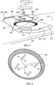
- Fig. 3 provides an exploded view of the components depicted in Fig. 2 .
- the board base 120 includes a circular hole or cutout 148.
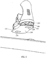
- the rim of the underside of the adjusting disk 140 and the rim of the hole 148 comprise corresponding evenly-spaced ridges or other shapes.
- Fig. 4 depicts the underside of an adjusting disk 140, according to an embodiment of the invention, illustrating the ridges that may interlock with corresponding ridges in the snowboard base 120.
- tightening the fasteners 130 causes the adjusting disk 140 to press the board base 120 against the snowboard deck 115.
- the alignment of the board base 120 relative to the snowboard deck 115 may be set, e.g., when the board base 120 is secured to the snowboard deck 115.
- the pressure exerted by the adjusting disk may hold the board base 120 firmly and securely to the snowboard deck 115, and the interlocking ridges in the adjusting disk 140 and the board base 120 may inhibit rotation of the board base 120 relative to the snowboard deck 115.
- the alignment of the board base 120 relative to the snowboard deck 115 may be adjusted by loosening the fasteners 130, rotating the board base 120 into a desired alignment, and then tightening the fasteners 130.
- the dimensions of the board base 120 and the adjusting disk 140 may be such that, e.g., when the fasteners 130 are fully tightened, the bottom of the adjusting disk 140 is flush with the bottom of the board base 120. Similarly, the top of the adjusting disk 140 may be flush with the top of the board base 120. Further, in an embodiment of the invention, some or all of the holes 145 in the adjusting disk 140 may be, e.g., countersunk or counterbored at the top, causing the tops of some or all of the fasteners 130 to be flush with the top of the adjusting disk 140 or below it when the fasteners are fully tightened.
- the board base 120 in an embodiment of the invention comprises one or more permanent magnets 150.
- the board base may comprise two cutouts 155, each with a flanged rim that is sufficient in extent and strength to retain one of the magnets 150 in the respective cutout 155 despite attraction between the magnet and any outside objects.
- one or more of the magnets 150 may be, e . g ., partially covered by, or encased in, a material such as nickel or plastic to protect and/or to improve the durability of the magnet 150.
- one or more of the magnets 150 may be glued or otherwise fixed to the body of the board base 120.
- one or more of the permanent magnets 150 may be embedded in the material of the board base 120.
- one or more of the magnets 150 may be fixed to the snowboard deck 115 in a manner capable of exerting suitable attractive and/or repulsive forces on an object above but relatively near to the board base 120.
- the board base 120 may comprise two separate sets of shelves 160, which project perpendicularly away from the snowboard deck 115.
- each shelf 160 may describe, e . g ., a portion of an hypothetical circle such that all shelves 160 describe respective portions of the same hypothetical circle.
- One set of shelves 160 may be, e.g., on the edge of the board base 120 nearest the user's toes.
- the toe side shelves 165 may comprise, e.g., two shelves.
- one of the toe side shelves 170 may be, e.g. 0,16 cm (1/16 of an inch) from the surface of the board base 120
- the other 175 may be, e.g ., 0,48 cm (3/16 of an inch) from the surface of the board base 120.
- the same or similar dimensions may be used, e . g ., for the two depicted heel-side shelves 180.
- the width of the shelves 160 may vary depending, e . g ., on the strength and flexibility of the material or materials used and the manner of construction; for example, in the depicted embodiment of the invention, the shelves 160 are 0,64 cm (1/4 of an inch) wide. In the depicted embodiment of the invention, all shelves 160 are the same thickness and width, but, in an embodiment of the invention, one or more of the shelves 160 may differ in thickness, width, or both from one or more other shelves 160.
- Some or all of the shelves 160 may in an embodiment of the invention, such as Figs. 2 and 3 depict, be made, e . g ., as integral parts of the board base 120 or as distinct parts, that may be affixed directly or indirectly to the board base 120, e . g ., during manufacture.
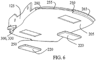
- a snowboard binding 110 may comprise a binding base 125.
- the binding base 125 is, in an embodiment of the invention, configured to receive and retain a boot (not pictured), which may be worn by the user while the snowboard is in use.
- a binding base 125 may in an embodiment of the invention be configured, e . g ., in a manner similar to that of a strap-in binding, such as described above, to receive a soft boot (not depicted) and to secure it in place with one or more adjustable straps that are capable of holding the boot against the base 205 of the binding base 125 and a highback 210.
- the binding base 125 is in the depicted embodiment of the invention configured to dock with the board base 120, e . g ., guided and/or otherwise assisted by magnetic forces.
- structures of the binding base 125 may be engaged with structures of the board base 120 to hold the bases together, and, while engaged, the bases may be secured to one another in a configuration suitable for use.
- a locking mechanism may hold the bases in an engaged and secured configuration until manually released.
- the base 205 of the binding base 125 may contain one or more permanent magnets 220.
- One or more of the magnets 220 may be affixed to and/or embedded in the base 205, e . g ., as one or more of the magnets 150 discussed previously may be affixed to and/or embedded in the board base 120.
- one or more of the magnets 220 may be, e . g ., partially covered by, or encased in, a material such as nickel or plastic to protect and/or to improve the durability of the magnet 220.
- no part of either magnet 220 protrudes from the lower surface of the base 205 of the binding base 125.
- the relative polarities of the magnet 220 nearest to the toe end of the binding base 125 and the magnet 150 nearest to the toe end of the board base 120, as installed, may be such that the magnets 150, 220 attract one another, e . g ., when the upright binding base 125 is placed vertically above the upper side of the board base 120, aligned, e . g ., as Fig. 7 depicts.
- the magnets 150, 220 nearest to the heel ends of the respective bases may be installed so that those magnets are also mutually attracted, e . g ., when the bases are aligned as Fig. 7 depicts.
- the respective polarities may also be chosen such that the respective pairs of magnets 150, 220 are mutually repelled, e.g., if the binding base 125 is rotated 180 degrees relative to the board base 120 from the alignment that Fig. 7 depicts.
- the corresponding magnets 150 in the board base 120 and the magnets 220 in the binding base 125 may be substantially equal in size.
- the corresponding magnets 150, 220 at each end of the respective bases 120, 125 may be vertically aligned relative to each other when the binding base 125 and the board base 120 are placed relative to one another, e . g ., at an angle such as Fig. 7 depicts.
- Figs. 1-7 depict, with magnets configured, e . g ., as discussed above, magnetic attraction may hold the board base 120 to the binding base 125 in an alignment, e . g ., as Fig. 7 depicts.
- the magnets 150, 220 may in an embodiment of the invention be chosen to be sufficiently strong such that the depicted alignment may be maintained, e . g ., against gravity and/or incidental forces, until the user chooses to exert sufficient force to disturb that alignment.
- Suitable magnets are known in the art and may comprise, e . g ., neodymium and/or other rare-earth magnets, but any sufficiently strong and compact magnets may be used in an embodiment of the invention.
- one or more magnets may be replaced, e . g ., with a piece of ferromagnetic material (not pictured).
- each piece of ferromagnetic material in one base may correspond, e . g ., to a magnet in the other base, e.g., such that magnetic attraction will pull the bases together into a docked configuration.
- a binding base 125 in an embodiment of the invention may comprise lip features 250, e . g ., corresponding to the shelf features 160 of the board base 120.
- the lip features 250 describe, e . g ., portions of an imaginary circle in a manner similar to that in which the shelves 160 of the board base 120 describe portions of an imaginary circle.
- the imaginary circle that the lip features 250 describe may in an embodiment of the invention have a slightly smaller diameter that that described by the shelves 160, which may, e . g ., be consistent with the functions of the lip and shelf features described below.
- the placement and dimensions of the lip features 250 may be such that, for some relative placements of the board base 120 and the binding base 125, the lip features 250 and shelves 160 may be in an underlapping/overlapping configuration, e . g ., such as Figs. 8-14 depict.
- the shelf may, e . g ., prevent the binding base 125 from being simply pulled apart from the board base 125.
- the orientation of the binding base 125 relative to the board base 120 must be changed, e . g ., by rotation of the binding base 125 in the opposite direction, before the bases may be separated.
- the lip features of the binding base may be approximately 1/16 of an inch thick and offset in height by 1/16 of an inch.
- the lower lips 255, 260 may in such an embodiment of the invention be, e.g., flush with the bottom of the binding base.
- the upper lips, 265, 270 may in such an embodiment be located, e . g ., 1/8 of an inch from the board base.
- the relative sizes and alignments of the shelves 160 and lip features 250 may in an embodiment of the invention be such that the lips 250 may slide relatively unimpeded below the respective corresponding shelves 160, e.g., as the binding base 125 is rotated relative to the board base 120, until a point of maximum rotation is achieved, e . g ., as described below.
- the relative tightness of the engagement of the bases may increase, e . g ., to prevent or reduce any wobbling or other unsteadiness in the joint.
- One or more of the shelves 160 and/or lips 250 may taper (not pictured) to increase this fimness, e . g ., as the relative rotation increases.
- the required rotational force may increase as the degree of rotation increases, but the required force may not require, e . g ., subjectively excessive exertion by the user.
- any such taper may, in an embodiment of the invention, be such that the relative tightness of the engagement of the bases is least at the point of initial engagement from, e . g ., a docked configuration.
- a docked configuration may make it easier for a user to initially engage the bases by increasing the likelihood that the lips will engage properly with the shelves.
- a board base 120 and a binding base 125 are in what may be referred to as a docked configuration.
- the corresponding meeting surfaces of the bases are sufficiently flush against one another to present no substantial impediments to rotating the bases relative to each other while maintaining substantial contact between the surfaces.
- no overlap exists between any of the lip features 250 and any of the shelf features such as might interfere with the contact between the meeting surfaces of the bases.
- Figs. 8-10 depict the relative positions of the lip features 250 and shelves 160 when the bases are in a docked configuration according to an embodiment of the invention.
- the magnets may tend to hold the bases in a docked alignment such as Fig. 7 depicts.
- geometry and/or one or more corresponding structures on one or both bases may serve to guide the bases into a docked configuration and/or to retain them in such a configuration, in addition to magnets as described above.
- any such structures may be designed not to interfere with such rotation: for example, a circular indentation (not pictured) in the underside of the binding base 125 may correspond to a circular raised portion (not pictured) on the upper side of the board base 120.
- the corresponding lip structures 250 and shelves 160 engage to retain the binding after minimal counterclockwise rotation of the binding base 125 relative to the board base 120.
- maximal counterclockwise rotation may be achieved when the lateral edges of the bases are evenly aligned with one another.
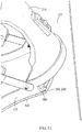
- the binding base 125 may rotate counterclockwise through an angle of 45 degrees, at which point a locking mechanism engages.
- Figs. 11-14 depict the bases in such a configuration according to an embodiment of the invention.
- one or more of the lips 250 may incorporate a projection 280 that may be placed to encounter the edge of one or more of the corresponding shelves 160, e.g., to impede rotation beyond the point of maximum relative rotation.
- Figs. 11-14 is illustrative and not limiting.
- the direction of rotation may be clockwise instead of counterclockwise.
- the angle of relative rotation traversed from the docked configuration to the locked configuration may be greater or lesser than 45 degrees.
- a locking mechanism may secure the bases in their relative positions, e . g ., making the snowboard and binding ready for riding.
- a locking mechanism comprises a sliding, spring-loaded latch.
- the latch may engage, e . g ., when the binding base has engaged with the board base and been rotated counterclockwise until the edges of the bases are flush with one another, and the latch may thereby maintain the relative positions of the bases, e . g ., while the user is riding the snowboard.
- the user may manually disengage the latch, e . g ., by sliding or otherwise moving one or more components, thereby allowing, e . g ., clockwise rotation of the binding base relative to the board base, returning the bases to a docked configuration, in which the bases may be disengaged.
- Figs. 15-22 depict a locking mechanism, including a latch as described above, according to an embodiment of the invention.
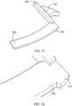
- Fig. 15 depicts a sliding latch 300, according to an embodiment of the invention, which incorporates a heel-side lip 270.
- the lip 270 incorporates a projection 310 shaped to push the latch 300 into the binding base 125 while the bases are engaged.
- the shape of the projection 310 combined with the corresponding shape of a shelf 180 ( Fig. 2 ) of the board base 120 ( Fig. 2 ) also allows the latch 300 to extend from the binding base 125 when the bases are rotated to the locking position.
- the projection may hold the bases in this relative position.
- Fig. 17 depicts the latch 300 assembled into the binding base 125 according to an embodiment of the invention.
- the heel-side lip 270 incorporated into the latch 300 may extend outwards from the heel side of the binding base 125 through a slot 315 in the binding base 125.
- the dimensions of the slot 315 may be, e . g ., slightly larger than those of the lip 270, chosen to allow the latch 300 to slide freely in the slot 315 yet minimize vertical and horizontal play of the latch 300 in the slot 315 while in use.
- the position of the slot 315 in the binding base 125 may be chosen, e.g., so that the lip 270 engages with the corresponding shelf 180 ( Fig. 2 ) on the board base 120 when the bases are docked and then rotated.
- the binding base 125 in an embodiment of the invention includes a receptacle 320 or guide configured to receive the end of the latch 300 opposite to the lip 270.
- a spring 325 may be held in the receptacle 320 such that, when the latch 300 is pushed into the binding base 125, the spring 325 exerts a force tending to push the latch back out.
- Fig. 18 depicts the binding base 125 with the receptacle 320 cut away to illustrate the relative placement of the latch 300, the spring 325, and the binding base 125 according to an embodiment of the invention.
- the configuration of the latch 300, receptacle 320, and binding base 125 may be such that at least a portion of the latch 300 remains within the receptacle 320 regardless of the degree to which the latch 300 has been pushed into the binding base 125 or extends outward from it, e.g ., to help maintain the relative alignment of the latch 300 and the binding base.
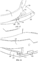
- Figs. 19-22 illustrate the relative position and interaction of the latch 300, the binding base 125, and the board base 120 as the bases are docked, engaged, and locked according to an exemplary embodiment of the invention.
- the bases have been docked, e.g ., as described above, but have not been engaged, e.g ., by rotation of the binding base 125 relative to the board base 120.
- the bases have been rotated from the docked position so that the lip 270 has begun to engage the shelf 180.
- one or more other lips may engage the respective corresponding shelves at a greater or smaller angle of relative rotation than that at which the lip 270 incorporated into the latch 300 begins to engage.
- the shape of the projection 310 from the lip 270 is such as to exert a force radially inward on the lip 270 as the degree of relative rotation increases, pushing the latch 300 into the binding base 125.
- Fig. 21 depicts the binding base 125 and the board base 120 at a slightly greater angle of rotation than that depicted in Fig. 20 , according to an embodiment of the invention.
- the shape of the projection 310 may be such that further rotation of the binding base 125 relative to the board base 120 will not push the latch 300 substantially further into the binding base.
- Fig. 22 depicts the binding base 125 and the board base 120 at maximal relative rotation, in a locked configuration, e . g ., suitable for use according to an embodiment of the invention.
- the shelf 180 may not extend to the outward lateral edge of the binding base 125. So configured, when maximal relative rotation is achieved, the projection 310 may be freed from the inward radial force and may consequently be pushed outward by the spring 325 (not pictured). In the depicted embodiment of the invention, the inner edge of the projection 310 may rest against the outer edge, e . g ., of the shelf 180 or its vertical support, thereby impeding clockwise rotation of the binding base 125 relative to the board base 120.
- the latch 300 may comprise, e.g ., a slider 330, which may be used to push the latch 300 back into the binding base 125, disengaging the locking mechanism and allowing the clockwise rotation of the binding base 125 relative to the board base 120. Such rotation may, in an embodiment of the invention, return the bases, e . g ., to a docked position, allowing the user to separate them.
- a slider 330 which may be used to push the latch 300 back into the binding base 125, disengaging the locking mechanism and allowing the clockwise rotation of the binding base 125 relative to the board base 120.
- Such rotation may, in an embodiment of the invention, return the bases, e . g ., to a docked position, allowing the user to separate them.
- a portion of the latch 300 may extend, e . g ., through a slot 335 ( Fig. 22 ) in the outer side of the binding base 125, and the slider 330 may be attached to the latch 300, e . g ., during assembly.
- Such a configuration may also, e.g ., further stabilize the relative alignment of the latch 300 relative to the binding base 125.
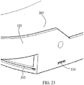
- Fig. 23 depicts a base 205 of a binding base 125 that incorporates a slot 315 for the lip 270 of a shelf and a slot 335 for passing part of the latch 300 through, to a slider 335, according to an embodiment of the invention.
- suitable materials for the board base 120, binding base 125, and/or latch 300 in an embodiment of the invention may include, e . g ., plastic (including but not limited to polycarbonate and/or other thermoplastics), nylon, glass injected plastic, carbon fiber, and aluminum and other lightweight, durable metals, among many other possibilities.
- the dimensions of the components of an embodiment of the invention may reflect the intended use of the embodiment, including, for example, considerations such as the expected sizes of the snowboard deck 115 to which the board base 120 may be secured and the boot (and, by extension, the user's foot) that may be secured within the binding base 125.
- the board base 120 may be roughly 15,24 cm (6 inches) wide (meaning left to right in relation to the user's foot and boot), approximately 22,86 cm (9 inches) long (meaning toes to heel in relation to the user's foot and boot), and approximately 0,48 cm (3/16 of an inch) thick.
- the board base 120 will match the outline dimensions of the binding base 125 to create a flush fit when the entire system is locked and operable. It will be appreciated that these dimensions may be departed from significantly, with or without maintaining any or all proportions, without affecting the operating principle of embodiments of the invention.
- an embodiment of the invention configured such that a user may dock, engage, and lock the bases as described herein in connection with embodiments of the invention may permit a user to easily secure the user's foot to a snowboard for use without use of the hands.
- a user may be seated, e . g ., on a ski lift, with one foot secured to a snowboard, e . g ., by a conventional binding or by a binding according to an embodiment of the invention.
- the user's other foot may be wearing a boot that is secured within a binding base 125 according to an embodiment of the invention, and the binding base 125 may correspond to a board base 120 that is permanently secured to the snowboard deck 115.
- the user may dock the board base 120 with the binding base 125, e.g., by moving a foot so that the bottom of the foot (and thus the bottom of the binding base 125) is within a few inches of the top of the board base 120, canted approximately 45 degrees counterclockwise to the board base.
- magnetic attraction may, e . g ., draw the board base 120 and the binding base 125 into a docked configuration.
- the user may then rotate the boot and the enclosing binding base 125 45 degrees counterclockwise to a point of maximum relative rotation, e . g ., as described above, at which the edges of the bases are flush with one another.
- the latch 300 may then engage, holding the bases in such a relative alignment until released by the user.
- the relative placement and sizes of the lips and shelves may in an embodiment of the invention hold the bases firmly together. While locked in such a position, the effect of the joined bases may, in an embodiment of the invention, be considered equivalent to creating a solid 1,11 cm (7/16 of an inch) base.
- Fig. 24 illustrates another embodiment of this invention in which there are three elements to the invention rather than just two.
- the board base 120 is as described above with regard to the embodiments illustrated in Figs. 1-23 .
- the binding 240 is a standard binding as is conventionally found in the snowboard industry except as to accept an intermediate adapter plate 242 secured to the bottom plate 244 of binding 240.
- Intermediate plate 242 includes the magnets on the underside (not shown) as they are found and shown in Fig. 5 , for example, as well as front lips 250 and 265, as illustratively depicted in Fig. 8 .
- the intermediate plate 242 is secured to the bottom plate 244 of binding 240, and in all respects the three-piece assembly shown in Fig. 24 operates substantially identical as the two-piece assembly shown in Figs. 1-23 except that when plate 242 is joined or connected to plate 244 of binding 240, there again is a two-piece assembly.
- Suitable bolts, screw or the like are provided to firmly connect plate 242 to the plate 244 of the binding 240.
- binding design of this invention can be utilized in any board sport that uses a binding, such as wakeboarding and kiteboarding/kitesurfing.
- Fig. 25 is a perspective view of another embodiment of this invention in which the front binding is capable of being rotated with respect to the board so that the front binding is parallel to the rear foot which has been released from the board so that the front and rear feet face forward, facilitating movement of the snowboarder when the rear foot is disconnected from the board.
- the binding comprises a lower plate 450 attached to the board with a rotatable binding 452 rotatable about a turret 454 centrally located between plate 450 and binding 452.
- the concept of using lips and flanges similar to 250 and 160 as in Fig. 8 to maintain the front binding locked in place when snowboarding may easily be seen in Fig. 25 .
- Fig. 26 is a top perspective view of another embodiment for the rear or front locking portion of the locking system of this invention.
- Pairs of cams 500 and 502 located at opposite sides of the front side, near the toes of the board base 120 are rotatable and interconnected through matching teeth 504 and 506, respectively, of the cams. Similar to the previous embodiment, overlapping features are used to secure the binding to the board base.
- lips 600 protrude from the base of the binding and are overlapped by cams 500 and 502 which serve in the place of shelves 180 of the prior embodiment.
- the cams are rotated out of the locking position by pushing downwardly on members 500 and 502, which consequently rotates counterclockwise, causing a clockwise rotation on the adjoining cam 502 via the interconnected teeth 504 and 506. This action frees up the locking system and enables the user to rotate the binding and remove the lip 600 from under the cams 500 and 502.
- This simple interconnected camming mechanism more easily facilitates release of the locking mechanism.
- Another embodiment of this invention is to extend the concept of the rotation elements to both lock and release the binding from the board to other boards both in wakeboarding and kiteboarding.
- the user is either pulled by the wind or pulled by a boat.
- this capability will be limited since the board can easily fall off of the user's feet. So if the user's foot is fixedly attached to the board via a more supportive binding that incorporates greater support along the Achilles tendon and top of the foot that then interlocks with the board, more difficult maneuvers may be performed without losing the board.
- the additional embodiments described above utilize the quick release and quick lock mechanism between the board and the binding as described with snowboards above.
- the board has attached thereto a plate with a lockable flange similar to elements 160, 165 of Fig. 8 and the binding has an insertable lip similar to 250, 265 of Fig. 8 to permit rotation between the boot and the board.
- the boot or binding includes magnets which match and align with magnets in the board so as to align these parts prior to rotation and locking. Thus, the board and binding do not become disengaged during intricate and forceful maneuvers with wakeboards or kiteboards.
Landscapes
- Engineering & Computer Science (AREA)
- Mechanical Engineering (AREA)
- Orthopedics, Nursing, And Contraception (AREA)
- Fittings On The Vehicle Exterior For Carrying Loads, And Devices For Holding Or Mounting Articles (AREA)
- Cleaning Of Streets, Tracks, Or Beaches (AREA)
- Footwear And Its Accessory, Manufacturing Method And Apparatuses (AREA)
- Clamps And Clips (AREA)
Claims (7)
- Un appareil de fixation pour planche (100), comprenant :une embase de fixation (125), configurée pour pouvoir être fixée à au moins une portion d'une planche (115), dans lequel la planche est une d'une planche à neige, planche de wakeboard ou une planche de kiteboard et dans lequel la portion de la planche comprend une embase de planche (120) ;l'embase de fixation étant configurée en outre pour recevoir une chaussure pendant que la chaussure est portée par un utilisateur ;l'embase de fixation étant configurée en outre pour pouvoir être arrimée à l'embase de planche ;l'embase de fixation, quand elle est arrimée à l'embase de planche, étant configurée en outre pour pivoter dans une première direction par rapport à l'embase de planche en entrant en prise avec une structure pour empêcher le désarrimage de l'embase de fixation par rapport à l'embase d'arrimage, caractérisé en ce quela première direction est en sens antihoraire ou horaire par rapport à l'embase de planche ;l'embase de fixation, après avoir pivoté dans la première direction, est configurée en outre pour pivoter dans une deuxième direction par rapport à l'embase de planche pour permettre la désolidarisation de l'embase de fixation par rapport à l'embase de planche ; etun ou plusieurs aimants permanents (220) sont configurés pour s'accoupler à au moins une de l'embase de fixation et l'embase de planche, dans lequel le ou les aimants permanents sont configurés en outre pour arrimer l'embase de fixation avec l'embase de planche avant que l'embase de fixation pivote dans la première direction.
- L'appareil de fixation pour planche selon la revendication 1, comprenant en outre un verrou configuré pour empêcher l'embase de fixation de pivoter dans la deuxième direction.
- L'appareil de fixation pour planche selon l'une quelconque des revendications précédentes, dans lequel au moins une de la première direction et la deuxième direction est au moins une d'une rotation horaire et antihoraire par rapport à l'embase de planche.
- L'appareil de fixation pour planche selon l'une quelconque des revendications précédentes, dans lequel au moins un des aimants permanents, quand il est arrimé, est configuré en outre pour s'aligner avec un deuxième aimant permanent (150), et dans lequel le au moins un des aimants permanents n'est pas aligné avec le deuxième aimant permanent après la rotation de l'embase de fixation dans la première direction.
- L'appareil de fixation pour planche selon la revendication 2, dans lequel le verrou est configuré pour mettre en prise mécaniquement l'embase de fixation quand l'embase de fixation pivote dans la première direction.
- L'appareil de fixation pour planche selon l'une quelconque des revendications précédentes, dans lequel au moins une de l'embase de planche et l'embase de fixation comprend un ou plusieurs rebords (160), et dans lequel au moins une de l'embase de planche et l'embase de fixation comprend une ou plusieurs pattes (250) et dans lequel les un ou plusieurs rebords sont situés relativement aux une ou plusieurs pattes de manière à empêcher le désarrimage de l'embase de fixation par rapport à l'embase de planche quand l'embase de fixation pivote dans la première direction.
- L'appareil de fixation pour planche selon l'une quelconque des revendications précédentes, dans lequel l'embase de fixation, quand elle a été arrimée initialement à l'embase de planche, n'est pas alignée avec l'embase de planche.
Applications Claiming Priority (2)
| Application Number | Priority Date | Filing Date | Title |
|---|---|---|---|
| US12/554,713 US8276921B2 (en) | 2009-09-04 | 2009-09-04 | Snowboard binding |
| PCT/US2010/047134 WO2011028656A1 (fr) | 2009-09-04 | 2010-08-30 | Fixation pour planche à neige et autres sports à planche |
Publications (3)
| Publication Number | Publication Date |
|---|---|
| EP2349509A1 EP2349509A1 (fr) | 2011-08-03 |
| EP2349509A4 EP2349509A4 (fr) | 2012-02-08 |
| EP2349509B1 true EP2349509B1 (fr) | 2017-04-05 |
Family
ID=43647116
Family Applications (1)
| Application Number | Title | Priority Date | Filing Date |
|---|---|---|---|
| EP10813095.6A Active EP2349509B1 (fr) | 2009-09-04 | 2010-08-30 | Fixation pour planche de glisse sur neige et autres planches de sport |
Country Status (9)
| Country | Link |
|---|---|
| US (1) | US8276921B2 (fr) |
| EP (1) | EP2349509B1 (fr) |
| JP (1) | JP2013503699A (fr) |
| KR (1) | KR20120047206A (fr) |
| CN (1) | CN102159288A (fr) |
| AR (1) | AR080394A1 (fr) |
| CA (1) | CA2737007A1 (fr) |
| RU (1) | RU2011108840A (fr) |
| WO (1) | WO2011028656A1 (fr) |
Families Citing this family (34)
| Publication number | Priority date | Publication date | Assignee | Title |
|---|---|---|---|---|
| US20110227317A1 (en) * | 2010-03-17 | 2011-09-22 | Holbird Jr Thomas | Adapter for Mounting Snowboard Bindings to Alpine Snow Skis |
| WO2012103480A1 (fr) | 2011-01-27 | 2012-08-02 | Brendan Walker | Fixations de sport de glisse |
| WO2013028918A1 (fr) * | 2011-08-23 | 2013-02-28 | Shuperstar Llc | Fixations de planche nautique, planches nautiques comprenant lesdites fixations et procédés associés |
| US8870212B2 (en) * | 2012-08-10 | 2014-10-28 | Noyes Britt Bouche, Inc. | Electromagnetically lockable rotating binding for a sportboard or the like |
| FR2996142B1 (fr) * | 2012-10-01 | 2014-10-24 | Christophe Etallaz | Systeme de fixation pour planche de surf des neiges de randonnee |
| US9004503B2 (en) * | 2012-11-16 | 2015-04-14 | Snowboard Sport Solutions, LLC | Rotatable binding system for snowboards |
| RU2543405C2 (ru) * | 2013-04-05 | 2015-02-27 | Дмитрий Александрович Ромашев | Система сбрасывания сноуборда в случае чрезвычайной ситуации |
| US9108102B2 (en) | 2013-08-16 | 2015-08-18 | Sean Tudor | Stylized apparatus for bindingly accepting a strap including snowboard improvements and accouturements |
| US9233296B2 (en) | 2014-02-24 | 2016-01-12 | Ob4 Systems, Inc. | Binding systems for boards and skis |
| US9149711B1 (en) * | 2014-11-14 | 2015-10-06 | The Burton Corporation | Snowboard binding and boot |
| KR200482328Y1 (ko) * | 2015-04-20 | 2017-01-11 | 나현명 | 호루라기 장치 |
| EP4066672A1 (fr) | 2016-10-26 | 2022-10-05 | NIKE Innovate C.V. | Structure de semelle de chaussure articulée pour rentrer le pied et procédé de fabrication |
| WO2018081260A1 (fr) | 2016-10-26 | 2018-05-03 | Nike Innovate C.V. | Composant de tige pour un article chaussant |
| US11304479B2 (en) | 2017-02-28 | 2022-04-19 | Nike, Inc. | Footwear with laceless fastening system |
| CN110913962B (zh) | 2017-03-14 | 2022-02-08 | 斯托普瑞尔发展有限责任公司 | 处理器控制的雪地运动靴结合 |
| CN110475592B (zh) * | 2017-03-31 | 2021-08-06 | 樟宜综合医院私人有限公司 | 脚固定组件和相关方法 |
| JP6153685B1 (ja) * | 2017-04-11 | 2017-06-28 | 株式会社 Jp Tight | スノーボードビンディング用プレート |
| US10758010B2 (en) | 2017-04-17 | 2020-09-01 | Nike, Inc. | Increased access footwear |
| CN114668212B (zh) | 2017-05-23 | 2023-07-25 | 耐克创新有限合伙公司 | 具有可移动鞋跟部分的后方进入式鞋类物品 |
| EP3629808B1 (fr) | 2017-05-23 | 2021-10-13 | Nike Innovate C.V. | Tige de chaussure dotée d'un système de fermeture à glissière mise en prise par un lacet |
| US10159310B2 (en) | 2017-05-25 | 2018-12-25 | Nike, Inc. | Rear closing upper for an article of footwear with front zipper to rear cord connection |
| NO342933B1 (no) | 2017-05-30 | 2018-09-03 | Rottefella As | Festemekanisme for et låseorgan som skal festes til en monteringsplate på en langrennsski |
| US10500475B2 (en) * | 2017-11-28 | 2019-12-10 | Daniel Joseph Walsh | Spacer for snowboard |
| US10646770B2 (en) | 2018-01-25 | 2020-05-12 | Spark R&DIP Holdings, LLC | Three degrees of freedom mounting system for snowboards and splitboards |
| US10827803B2 (en) | 2018-04-13 | 2020-11-10 | Nike, Inc. | Footwear fastening system |
| US10471334B1 (en) * | 2018-10-22 | 2019-11-12 | Thomas K Iverson | Universal shoe harness for Nordic ski |
| CN115844103B (zh) | 2018-12-28 | 2026-03-24 | 耐克创新有限合伙公司 | 具有活动相接鞋底结构的易于进入的鞋 |
| US11696615B2 (en) | 2019-02-25 | 2023-07-11 | Stop River Development LLC | Safety mechanism for use with snow sport boot and binding system |
| US11140941B2 (en) | 2019-05-03 | 2021-10-12 | Nike, Inc. | Footwear upper with unitary support frame |
| CN110215016B (zh) * | 2019-05-17 | 2024-08-20 | 天津腾达集团有限公司 | 一种特种户外鞋面自动点烫生产设备 |
| EP4044862B1 (fr) | 2019-10-18 | 2025-06-18 | NIKE Innovate C.V. | Article chaussant à accès facile avec bloqueur de cordon |
| CN114727688B (zh) | 2019-11-25 | 2024-06-18 | 耐克创新有限合伙公司 | 用于可穿戴物品的张力保持系统 |
| KR102369891B1 (ko) * | 2021-09-24 | 2022-03-02 | 김상우 | 스노우보드 데크 |
| EP4626275A1 (fr) | 2022-11-28 | 2025-10-08 | NIKE Innovate C.V. | Article chaussant doté d'une structure de semelle articulée pour faciliter l'accès |
Family Cites Families (60)
| Publication number | Priority date | Publication date | Assignee | Title |
|---|---|---|---|---|
| DE1428870C3 (de) * | 1963-08-16 | 1973-12-13 | Mueller, Hans, Dipl.-Kfm., 4307 Kettwig | Magnetische Verbindung von einem Skistiefel mit einem Ski |
| US3667771A (en) * | 1969-07-07 | 1972-06-06 | Richard C Larson | Adjustable magnetic ski binding |
| BE754859A (fr) * | 1969-08-27 | 1971-01-18 | Sommer Reinhold | Attache de securite pour skis |
| US3927897A (en) * | 1974-06-24 | 1975-12-23 | Donald M Olson | Magnetic release system for snow skis |
| FR2363343A1 (fr) * | 1976-09-03 | 1978-03-31 | Salomon & Fils F | Fixation de securite declenchable pour ski |
| US4741550A (en) * | 1985-11-15 | 1988-05-03 | David Dennis | Releasable binding system for snowboarding |
| US4652007A (en) * | 1985-11-15 | 1987-03-24 | David Dennis | Releasable binding system for snowboarding |
| USRE33544E (en) * | 1985-11-15 | 1991-02-26 | Look Alpine Products, Inc. | Releasable binding system for snowboarding |
| US5028068A (en) * | 1989-09-15 | 1991-07-02 | Donovan Matt J | Quick-action adjustable snow boot binding mounting |
| US5035443A (en) * | 1990-03-27 | 1991-07-30 | Kincheloe Chris V | Releasable snowboard binding |
| US5261689A (en) * | 1992-01-28 | 1993-11-16 | Burton Corporation Usa | Snowboard boot binding system |
| US5354088A (en) * | 1993-03-15 | 1994-10-11 | Vetter Dennis A | Boot binding coupling for snow boards |
| US5362087A (en) * | 1993-08-12 | 1994-11-08 | Troy Agid | Snowboard binding release apparatus |
| US5743550A (en) * | 1994-02-12 | 1998-04-28 | Frohwein; Otto | Electronically controlled safety binding for skis and snow board |
| US5505478A (en) * | 1994-08-17 | 1996-04-09 | Napoliello; Michael | Releasable mounting for a snowboard binding |
| US5553883A (en) * | 1995-04-06 | 1996-09-10 | Erb; George A. | Snowboard binding which permits angular reorientation of a user's foot while maintaining that foot attached to the snowboard |
| US5499837A (en) * | 1995-07-31 | 1996-03-19 | Hale; Joseph P. | Swivelable mount for snowboard and wakeboard |
| US5762358A (en) * | 1996-06-24 | 1998-06-09 | Hale; Joseph P. | Swivelable bindings mount for a snowboard |
| ATE217206T1 (de) * | 1996-06-25 | 2002-05-15 | Richard W Berger | Snowboardbindung |
| US5695210A (en) * | 1996-07-26 | 1997-12-09 | Goss; Bruce R. | Releasable snowboard binding |
| US5941552A (en) * | 1996-12-20 | 1999-08-24 | Bc Creations, Inc. | Adjustable snowboard binding apparatus and method |
| US5906388A (en) * | 1997-01-14 | 1999-05-25 | Quiksilver, Inc. | Footwear mounting system |
| DE69817585T2 (de) * | 1997-04-18 | 2004-06-24 | The Burton Corp. | Aktives kupplungsystem zur kupplung eines snowboardstiefels an einer bindung |
| JPH10314365A (ja) | 1997-05-23 | 1998-12-02 | Hitachi Metals Ltd | スノーボード用磁気装置 |
| US6189899B1 (en) * | 1997-07-28 | 2001-02-20 | Stephen R. Carlson | Longitudinally adjustable mount for a snowboard binding |
| US6227552B1 (en) * | 1997-10-06 | 2001-05-08 | Marker Deutschland Gmbh | Snowboard binding with conical adapter |
| US5967542A (en) * | 1997-11-25 | 1999-10-19 | Sims Sports, Inc. | Mounting disk and base for snowboard binding |
| US6189913B1 (en) * | 1997-12-18 | 2001-02-20 | K-2 Corporation | Step-in snowboard binding and boot therefor |
| US20030090072A1 (en) * | 1998-02-17 | 2003-05-15 | Cole Charles D. | Freely rotatable binding for snowboarding and other single-board sports |
| US5954357A (en) * | 1998-04-09 | 1999-09-21 | Golling; Eugene J. | Apparatus for gliding over snow |
| US6224086B1 (en) * | 1998-04-09 | 2001-05-01 | Eugene J. Golling | Apparatus for gliding over snow |
| US6022040A (en) * | 1998-04-23 | 2000-02-08 | Buzbee; Douglas C. | Freely rotating step-in snowboard binding |
| US6206403B1 (en) * | 1998-06-26 | 2001-03-27 | Nike International, Inc. | Snowboard strap binding |
| AUPP590198A0 (en) * | 1998-09-14 | 1998-10-08 | Griplock Pty Limited | Sporting equipment binding apparatus |
| US6315305B1 (en) * | 2000-02-23 | 2001-11-13 | Yu Tze Gien | Snowboard binding having adjustable toe |
| US6290243B1 (en) * | 2000-03-04 | 2001-09-18 | Bc Creations, Inc. | Angular displacement control apparatus and method for rotationally adjustable snowboard bindings |
| US7267357B2 (en) * | 2001-02-15 | 2007-09-11 | Miller Sports International, Inc. | Multi-function binding system |
| US6557866B2 (en) * | 2001-03-09 | 2003-05-06 | Dennis Jones | Snowboard binding |
| US6983952B2 (en) * | 2001-10-02 | 2006-01-10 | Eugene Golling | Apparatus for gliding over snow |
| US6616151B1 (en) * | 2001-10-02 | 2003-09-09 | Eugene Golling | Apparatus for gliding over snow |
| US20030075890A1 (en) * | 2001-10-22 | 2003-04-24 | Jacobs Robert A. | Magnetic skateboard attachment system |
| US20030094788A1 (en) * | 2001-10-22 | 2003-05-22 | Jacobs Robert A. | Magnetic snow equipment attachment system |
| US6722688B2 (en) * | 2001-11-21 | 2004-04-20 | The Burton Corporation | Snowboard binding system |
| US6575489B1 (en) * | 2002-07-05 | 2003-06-10 | Rick Albert White | Snowboard rotatable binding conversion apparatus |
| WO2004069350A2 (fr) * | 2003-01-31 | 2004-08-19 | Marc Sacco | Systeme de reglage de la fixation |
| US6871869B2 (en) * | 2003-01-31 | 2005-03-29 | Shimano Inc. | Snowboard binding |
| FR2851173B1 (fr) | 2003-02-17 | 2006-07-14 | Philippe Jean Riandet | Skateboard magnetique et derives |
| ATE330678T1 (de) * | 2003-02-20 | 2006-07-15 | Jean-Pierre Edmond | Bindung zur befestigung eines schuhs an einem schneegleitbrett |
| US20070080518A1 (en) | 2004-03-26 | 2007-04-12 | Carvajal Richard D I | Autonomous electromagnetic control system for binding boots to a snowboard, skis, or similar |
| US7270337B1 (en) * | 2004-12-03 | 2007-09-18 | Robert L Carotenuto | Pivot plate apparatus for snowboards |
| US7338067B2 (en) * | 2005-03-07 | 2008-03-04 | Flaig Theodore J | Magnetic method and apparatus for increasing foot traction on sports boards |
| EP1709999A1 (fr) | 2005-04-06 | 2006-10-11 | Ezio Panzeri | Fixation magnetique |
| GB2428012A (en) * | 2005-07-07 | 2007-01-17 | Ezio Panzeri | Rotating connection system |
| US7841614B2 (en) * | 2005-10-25 | 2010-11-30 | Saloman S.A.S. | Safety binding |
| US7296805B2 (en) * | 2005-11-23 | 2007-11-20 | Lindemann Carl T | Snowboard binding |
| US7416191B2 (en) * | 2006-01-17 | 2008-08-26 | Tadashi Yoshino | Binding device for snowboard |
| US7220158B1 (en) * | 2006-01-18 | 2007-05-22 | Bradley Kenneth Norris | Sport board contact system |
| US8448975B2 (en) * | 2007-12-21 | 2013-05-28 | Dan Kostantin | Step-in telemark ski binding |
| US8065819B2 (en) * | 2008-03-05 | 2011-11-29 | Steven Kaufman | Hands-free step-in closure apparatus |
| US7823300B2 (en) * | 2008-05-20 | 2010-11-02 | Cedar Ridge Research, Llc | Correlated magnetic footwear and method for using the correlated magnetic footwear |
-
2009
- 2009-09-04 US US12/554,713 patent/US8276921B2/en active Active
-
2010
- 2010-08-30 WO PCT/US2010/047134 patent/WO2011028656A1/fr not_active Ceased
- 2010-08-30 RU RU2011108840/12A patent/RU2011108840A/ru not_active Application Discontinuation
- 2010-08-30 JP JP2012527947A patent/JP2013503699A/ja active Pending
- 2010-08-30 KR KR1020117005599A patent/KR20120047206A/ko not_active Withdrawn
- 2010-08-30 EP EP10813095.6A patent/EP2349509B1/fr active Active
- 2010-08-30 CA CA2737007A patent/CA2737007A1/fr not_active Abandoned
- 2010-08-30 CN CN2010800025564A patent/CN102159288A/zh active Pending
-
2011
- 2011-03-09 AR ARP110100738A patent/AR080394A1/es unknown
Also Published As
| Publication number | Publication date |
|---|---|
| AR080394A1 (es) | 2012-04-04 |
| CA2737007A1 (fr) | 2011-03-10 |
| JP2013503699A (ja) | 2013-02-04 |
| US8276921B2 (en) | 2012-10-02 |
| EP2349509A1 (fr) | 2011-08-03 |
| US20110057420A1 (en) | 2011-03-10 |
| KR20120047206A (ko) | 2012-05-11 |
| WO2011028656A1 (fr) | 2011-03-10 |
| CN102159288A (zh) | 2011-08-17 |
| RU2011108840A (ru) | 2012-09-20 |
| EP2349509A4 (fr) | 2012-02-08 |
Similar Documents
| Publication | Publication Date | Title |
|---|---|---|
| EP2349509B1 (fr) | Fixation pour planche de glisse sur neige et autres planches de sport | |
| US8894075B2 (en) | Board sport bindings | |
| US6994370B2 (en) | Adjustable rotatable sports board boot binding | |
| US5826910A (en) | Swivelable snowboard bindings | |
| US5553883A (en) | Snowboard binding which permits angular reorientation of a user's foot while maintaining that foot attached to the snowboard | |
| US8128117B2 (en) | Tool-free adjustable binding for sports board | |
| US6450511B1 (en) | Snowboard binding mount assembly | |
| US9452344B2 (en) | Puck system | |
| US20160296825A1 (en) | Pivoting magnetic binding system for sports boards | |
| WO2012016204A1 (fr) | Adaptateur de réglage par rotation pour laçage de chaussures de sport montantes | |
| CA2699473A1 (fr) | Systeme de liaison multifonction | |
| WO2004069350A2 (fr) | Systeme de reglage de la fixation | |
| EP2205331B1 (fr) | Planche à neige avec dispositif de freinage rétractable | |
| US7270337B1 (en) | Pivot plate apparatus for snowboards | |
| US9248366B2 (en) | Board sport binding | |
| US11590407B2 (en) | Expandable snowshoe attachment for snowboard bindings | |
| WO2012177783A2 (fr) | Fixations de planche à neige améliorées | |
| US10258861B2 (en) | Sport board binding system | |
| WO1999041130A1 (fr) | Fixation a rotation libre pour surf des neiges et autres sports a planche unique | |
| CA3026280C (fr) | Systeme de fixation de planche de sport | |
| EP2673059B1 (fr) | Support pour mollet amovible (highback) | |
| US9895596B2 (en) | Releasable binding system |
Legal Events
| Date | Code | Title | Description |
|---|---|---|---|
| PUAI | Public reference made under article 153(3) epc to a published international application that has entered the european phase |
Free format text: ORIGINAL CODE: 0009012 |
|
| 17P | Request for examination filed |
Effective date: 20110309 |
|
| AK | Designated contracting states |
Kind code of ref document: A1 Designated state(s): AL AT BE BG CH CY CZ DE DK EE ES FI FR GB GR HR HU IE IS IT LI LT LU LV MC MK MT NL NO PL PT RO SE SI SK SM TR |
|
| AX | Request for extension of the european patent |
Extension state: BA ME RS |
|
| A4 | Supplementary search report drawn up and despatched |
Effective date: 20120111 |
|
| RIC1 | Information provided on ipc code assigned before grant |
Ipc: A63C 9/08 20060101ALI20120104BHEP Ipc: A63C 9/00 20060101AFI20120104BHEP |
|
| REG | Reference to a national code |
Ref country code: HK Ref legal event code: DE Ref document number: 1160415 Country of ref document: HK |
|
| 17Q | First examination report despatched |
Effective date: 20150401 |
|
| REG | Reference to a national code |
Ref country code: DE Ref legal event code: R079 Ref document number: 602010041364 Country of ref document: DE Free format text: PREVIOUS MAIN CLASS: A63C0009000000 Ipc: A63C0010000000 |
|
| RIC1 | Information provided on ipc code assigned before grant |
Ipc: A63C 9/08 20120101ALI20160414BHEP Ipc: A63C 10/14 20120101ALI20160414BHEP Ipc: A63C 10/06 20120101ALI20160414BHEP Ipc: A63C 10/00 20120101AFI20160414BHEP Ipc: A63C 10/18 20120101ALI20160414BHEP Ipc: A63C 10/24 20120101ALI20160414BHEP |
|
| GRAP | Despatch of communication of intention to grant a patent |
Free format text: ORIGINAL CODE: EPIDOSNIGR1 |
|
| INTG | Intention to grant announced |
Effective date: 20160524 |
|
| GRAS | Grant fee paid |
Free format text: ORIGINAL CODE: EPIDOSNIGR3 |
|
| GRAA | (expected) grant |
Free format text: ORIGINAL CODE: 0009210 |
|
| AK | Designated contracting states |
Kind code of ref document: B1 Designated state(s): AL AT BE BG CH CY CZ DE DK EE ES FI FR GB GR HR HU IE IS IT LI LT LU LV MC MK MT NL NO PL PT RO SE SI SK SM TR |
|
| AX | Request for extension of the european patent |
Extension state: BA ME RS |
|
| REG | Reference to a national code |
Ref country code: GB Ref legal event code: FG4D |
|
| REG | Reference to a national code |
Ref country code: CH Ref legal event code: EP |
|
| REG | Reference to a national code |
Ref country code: AT Ref legal event code: REF Ref document number: 881250 Country of ref document: AT Kind code of ref document: T Effective date: 20170415 |
|
| REG | Reference to a national code |
Ref country code: IE Ref legal event code: FG4D |
|
| REG | Reference to a national code |
Ref country code: DE Ref legal event code: R096 Ref document number: 602010041364 Country of ref document: DE |
|
| REG | Reference to a national code |
Ref country code: NL Ref legal event code: MP Effective date: 20170405 |
|
| REG | Reference to a national code |
Ref country code: LT Ref legal event code: MG4D |
|
| REG | Reference to a national code |
Ref country code: AT Ref legal event code: MK05 Ref document number: 881250 Country of ref document: AT Kind code of ref document: T Effective date: 20170405 |
|
| PG25 | Lapsed in a contracting state [announced via postgrant information from national office to epo] |
Ref country code: NL Free format text: LAPSE BECAUSE OF FAILURE TO SUBMIT A TRANSLATION OF THE DESCRIPTION OR TO PAY THE FEE WITHIN THE PRESCRIBED TIME-LIMIT Effective date: 20170405 |
|
| PG25 | Lapsed in a contracting state [announced via postgrant information from national office to epo] |
Ref country code: GR Free format text: LAPSE BECAUSE OF FAILURE TO SUBMIT A TRANSLATION OF THE DESCRIPTION OR TO PAY THE FEE WITHIN THE PRESCRIBED TIME-LIMIT Effective date: 20170706 Ref country code: FI Free format text: LAPSE BECAUSE OF FAILURE TO SUBMIT A TRANSLATION OF THE DESCRIPTION OR TO PAY THE FEE WITHIN THE PRESCRIBED TIME-LIMIT Effective date: 20170405 Ref country code: HR Free format text: LAPSE BECAUSE OF FAILURE TO SUBMIT A TRANSLATION OF THE DESCRIPTION OR TO PAY THE FEE WITHIN THE PRESCRIBED TIME-LIMIT Effective date: 20170405 Ref country code: AT Free format text: LAPSE BECAUSE OF FAILURE TO SUBMIT A TRANSLATION OF THE DESCRIPTION OR TO PAY THE FEE WITHIN THE PRESCRIBED TIME-LIMIT Effective date: 20170405 Ref country code: LT Free format text: LAPSE BECAUSE OF FAILURE TO SUBMIT A TRANSLATION OF THE DESCRIPTION OR TO PAY THE FEE WITHIN THE PRESCRIBED TIME-LIMIT Effective date: 20170405 Ref country code: NO Free format text: LAPSE BECAUSE OF FAILURE TO SUBMIT A TRANSLATION OF THE DESCRIPTION OR TO PAY THE FEE WITHIN THE PRESCRIBED TIME-LIMIT Effective date: 20170705 |
|
| PG25 | Lapsed in a contracting state [announced via postgrant information from national office to epo] |
Ref country code: BG Free format text: LAPSE BECAUSE OF FAILURE TO SUBMIT A TRANSLATION OF THE DESCRIPTION OR TO PAY THE FEE WITHIN THE PRESCRIBED TIME-LIMIT Effective date: 20170705 Ref country code: LV Free format text: LAPSE BECAUSE OF FAILURE TO SUBMIT A TRANSLATION OF THE DESCRIPTION OR TO PAY THE FEE WITHIN THE PRESCRIBED TIME-LIMIT Effective date: 20170405 Ref country code: PL Free format text: LAPSE BECAUSE OF FAILURE TO SUBMIT A TRANSLATION OF THE DESCRIPTION OR TO PAY THE FEE WITHIN THE PRESCRIBED TIME-LIMIT Effective date: 20170405 Ref country code: IS Free format text: LAPSE BECAUSE OF FAILURE TO SUBMIT A TRANSLATION OF THE DESCRIPTION OR TO PAY THE FEE WITHIN THE PRESCRIBED TIME-LIMIT Effective date: 20170805 Ref country code: SE Free format text: LAPSE BECAUSE OF FAILURE TO SUBMIT A TRANSLATION OF THE DESCRIPTION OR TO PAY THE FEE WITHIN THE PRESCRIBED TIME-LIMIT Effective date: 20170405 |
|
| REG | Reference to a national code |
Ref country code: DE Ref legal event code: R097 Ref document number: 602010041364 Country of ref document: DE |
|
| PG25 | Lapsed in a contracting state [announced via postgrant information from national office to epo] |
Ref country code: SK Free format text: LAPSE BECAUSE OF FAILURE TO SUBMIT A TRANSLATION OF THE DESCRIPTION OR TO PAY THE FEE WITHIN THE PRESCRIBED TIME-LIMIT Effective date: 20170405 Ref country code: EE Free format text: LAPSE BECAUSE OF FAILURE TO SUBMIT A TRANSLATION OF THE DESCRIPTION OR TO PAY THE FEE WITHIN THE PRESCRIBED TIME-LIMIT Effective date: 20170405 Ref country code: CZ Free format text: LAPSE BECAUSE OF FAILURE TO SUBMIT A TRANSLATION OF THE DESCRIPTION OR TO PAY THE FEE WITHIN THE PRESCRIBED TIME-LIMIT Effective date: 20170405 Ref country code: RO Free format text: LAPSE BECAUSE OF FAILURE TO SUBMIT A TRANSLATION OF THE DESCRIPTION OR TO PAY THE FEE WITHIN THE PRESCRIBED TIME-LIMIT Effective date: 20170405 Ref country code: DK Free format text: LAPSE BECAUSE OF FAILURE TO SUBMIT A TRANSLATION OF THE DESCRIPTION OR TO PAY THE FEE WITHIN THE PRESCRIBED TIME-LIMIT Effective date: 20170405 |
|
| PLBE | No opposition filed within time limit |
Free format text: ORIGINAL CODE: 0009261 |
|
| STAA | Information on the status of an ep patent application or granted ep patent |
Free format text: STATUS: NO OPPOSITION FILED WITHIN TIME LIMIT |
|
| PG25 | Lapsed in a contracting state [announced via postgrant information from national office to epo] |
Ref country code: SM Free format text: LAPSE BECAUSE OF FAILURE TO SUBMIT A TRANSLATION OF THE DESCRIPTION OR TO PAY THE FEE WITHIN THE PRESCRIBED TIME-LIMIT Effective date: 20170405 Ref country code: IT Free format text: LAPSE BECAUSE OF FAILURE TO SUBMIT A TRANSLATION OF THE DESCRIPTION OR TO PAY THE FEE WITHIN THE PRESCRIBED TIME-LIMIT Effective date: 20170405 |
|
| REG | Reference to a national code |
Ref country code: DE Ref legal event code: R119 Ref document number: 602010041364 Country of ref document: DE |
|
| 26N | No opposition filed |
Effective date: 20180108 |
|
| REG | Reference to a national code |
Ref country code: CH Ref legal event code: PL Ref country code: HK Ref legal event code: WD Ref document number: 1160415 Country of ref document: HK |
|
| PG25 | Lapsed in a contracting state [announced via postgrant information from national office to epo] |
Ref country code: MC Free format text: LAPSE BECAUSE OF FAILURE TO SUBMIT A TRANSLATION OF THE DESCRIPTION OR TO PAY THE FEE WITHIN THE PRESCRIBED TIME-LIMIT Effective date: 20170405 |
|
| GBPC | Gb: european patent ceased through non-payment of renewal fee |
Effective date: 20170830 |
|
| PG25 | Lapsed in a contracting state [announced via postgrant information from national office to epo] |
Ref country code: CH Free format text: LAPSE BECAUSE OF NON-PAYMENT OF DUE FEES Effective date: 20170831 Ref country code: LI Free format text: LAPSE BECAUSE OF NON-PAYMENT OF DUE FEES Effective date: 20170831 |
|
| REG | Reference to a national code |
Ref country code: FR Ref legal event code: ST Effective date: 20180430 |
|
| REG | Reference to a national code |
Ref country code: IE Ref legal event code: MM4A |
|
| PG25 | Lapsed in a contracting state [announced via postgrant information from national office to epo] |
Ref country code: SI Free format text: LAPSE BECAUSE OF FAILURE TO SUBMIT A TRANSLATION OF THE DESCRIPTION OR TO PAY THE FEE WITHIN THE PRESCRIBED TIME-LIMIT Effective date: 20170405 |
|
| REG | Reference to a national code |
Ref country code: BE Ref legal event code: MM Effective date: 20170831 |
|
| PG25 | Lapsed in a contracting state [announced via postgrant information from national office to epo] |
Ref country code: LU Free format text: LAPSE BECAUSE OF NON-PAYMENT OF DUE FEES Effective date: 20170830 |
|
| PG25 | Lapsed in a contracting state [announced via postgrant information from national office to epo] |
Ref country code: GB Free format text: LAPSE BECAUSE OF NON-PAYMENT OF DUE FEES Effective date: 20170830 Ref country code: DE Free format text: LAPSE BECAUSE OF NON-PAYMENT OF DUE FEES Effective date: 20180301 Ref country code: IE Free format text: LAPSE BECAUSE OF NON-PAYMENT OF DUE FEES Effective date: 20170830 |
|
| PG25 | Lapsed in a contracting state [announced via postgrant information from national office to epo] |
Ref country code: FR Free format text: LAPSE BECAUSE OF NON-PAYMENT OF DUE FEES Effective date: 20170831 Ref country code: BE Free format text: LAPSE BECAUSE OF NON-PAYMENT OF DUE FEES Effective date: 20170831 |
|
| PG25 | Lapsed in a contracting state [announced via postgrant information from national office to epo] |
Ref country code: MT Free format text: LAPSE BECAUSE OF NON-PAYMENT OF DUE FEES Effective date: 20170830 |
|
| PG25 | Lapsed in a contracting state [announced via postgrant information from national office to epo] |
Ref country code: HU Free format text: LAPSE BECAUSE OF FAILURE TO SUBMIT A TRANSLATION OF THE DESCRIPTION OR TO PAY THE FEE WITHIN THE PRESCRIBED TIME-LIMIT; INVALID AB INITIO Effective date: 20100830 |
|
| PG25 | Lapsed in a contracting state [announced via postgrant information from national office to epo] |
Ref country code: ES Free format text: LAPSE BECAUSE OF NON-PAYMENT OF DUE FEES Effective date: 20170405 |
|
| PG25 | Lapsed in a contracting state [announced via postgrant information from national office to epo] |
Ref country code: CY Free format text: LAPSE BECAUSE OF NON-PAYMENT OF DUE FEES Effective date: 20170405 |
|
| PG25 | Lapsed in a contracting state [announced via postgrant information from national office to epo] |
Ref country code: MK Free format text: LAPSE BECAUSE OF FAILURE TO SUBMIT A TRANSLATION OF THE DESCRIPTION OR TO PAY THE FEE WITHIN THE PRESCRIBED TIME-LIMIT Effective date: 20170405 |
|
| PG25 | Lapsed in a contracting state [announced via postgrant information from national office to epo] |
Ref country code: TR Free format text: LAPSE BECAUSE OF FAILURE TO SUBMIT A TRANSLATION OF THE DESCRIPTION OR TO PAY THE FEE WITHIN THE PRESCRIBED TIME-LIMIT Effective date: 20170405 |
|
| PG25 | Lapsed in a contracting state [announced via postgrant information from national office to epo] |
Ref country code: PT Free format text: LAPSE BECAUSE OF FAILURE TO SUBMIT A TRANSLATION OF THE DESCRIPTION OR TO PAY THE FEE WITHIN THE PRESCRIBED TIME-LIMIT Effective date: 20170405 |
|
| PG25 | Lapsed in a contracting state [announced via postgrant information from national office to epo] |
Ref country code: AL Free format text: LAPSE BECAUSE OF FAILURE TO SUBMIT A TRANSLATION OF THE DESCRIPTION OR TO PAY THE FEE WITHIN THE PRESCRIBED TIME-LIMIT Effective date: 20170405 |