EP2350575B1 - Messung des flusses viskoser flüssigkeiten unter verwendung einer differenzdruckmessung und einer sonargemessenen geschwindigkeit - Google Patents
Messung des flusses viskoser flüssigkeiten unter verwendung einer differenzdruckmessung und einer sonargemessenen geschwindigkeit Download PDFInfo
- Publication number
- EP2350575B1 EP2350575B1 EP09740574.0A EP09740574A EP2350575B1 EP 2350575 B1 EP2350575 B1 EP 2350575B1 EP 09740574 A EP09740574 A EP 09740574A EP 2350575 B1 EP2350575 B1 EP 2350575B1
- Authority
- EP
- European Patent Office
- Prior art keywords
- fluid flow
- pressure
- reynolds number
- determining
- velocity
- Prior art date
- Legal status (The legal status is an assumption and is not a legal conclusion. Google has not performed a legal analysis and makes no representation as to the accuracy of the status listed.)
- Active
Links
Images


Classifications
-
- G—PHYSICS
- G01—MEASURING; TESTING
- G01F—MEASURING VOLUME, VOLUME FLOW, MASS FLOW OR LIQUID LEVEL; METERING BY VOLUME
- G01F1/00—Measuring the volume flow or mass flow of fluid or fluent solid material wherein the fluid passes through a meter in a continuous flow
- G01F1/66—Measuring the volume flow or mass flow of fluid or fluent solid material wherein the fluid passes through a meter in a continuous flow by measuring frequency, phase shift or propagation time of electromagnetic or other waves, e.g. using ultrasonic flowmeters
- G01F1/667—Arrangements of transducers for ultrasonic flowmeters; Circuits for operating ultrasonic flowmeters
-
- G—PHYSICS
- G01—MEASURING; TESTING
- G01F—MEASURING VOLUME, VOLUME FLOW, MASS FLOW OR LIQUID LEVEL; METERING BY VOLUME
- G01F1/00—Measuring the volume flow or mass flow of fluid or fluent solid material wherein the fluid passes through a meter in a continuous flow
- G01F1/704—Measuring the volume flow or mass flow of fluid or fluent solid material wherein the fluid passes through a meter in a continuous flow using marked regions or existing inhomogeneities within the fluid stream, e.g. statistically occurring variations in a fluid parameter
- G01F1/708—Measuring the time taken to traverse a fixed distance
- G01F1/7082—Measuring the time taken to traverse a fixed distance using acoustic detecting arrangements
-
- G—PHYSICS
- G01—MEASURING; TESTING
- G01F—MEASURING VOLUME, VOLUME FLOW, MASS FLOW OR LIQUID LEVEL; METERING BY VOLUME
- G01F1/00—Measuring the volume flow or mass flow of fluid or fluent solid material wherein the fluid passes through a meter in a continuous flow
- G01F1/704—Measuring the volume flow or mass flow of fluid or fluent solid material wherein the fluid passes through a meter in a continuous flow using marked regions or existing inhomogeneities within the fluid stream, e.g. statistically occurring variations in a fluid parameter
- G01F1/708—Measuring the time taken to traverse a fixed distance
- G01F1/712—Measuring the time taken to traverse a fixed distance using auto-correlation or cross-correlation detection means
-
- G—PHYSICS
- G01—MEASURING; TESTING
- G01F—MEASURING VOLUME, VOLUME FLOW, MASS FLOW OR LIQUID LEVEL; METERING BY VOLUME
- G01F15/00—Details of, or accessories for, apparatus of groups G01F1/00 - G01F13/00 insofar as such details or appliances are not adapted to particular types of such apparatus
- G01F15/02—Compensating or correcting for variations in pressure, density or temperature
- G01F15/022—Compensating or correcting for variations in pressure, density or temperature using electrical means
- G01F15/024—Compensating or correcting for variations in pressure, density or temperature using electrical means involving digital counting
-
- G—PHYSICS
- G01—MEASURING; TESTING
- G01N—INVESTIGATING OR ANALYSING MATERIALS BY DETERMINING THEIR CHEMICAL OR PHYSICAL PROPERTIES
- G01N11/00—Investigating flow properties of materials, e.g. viscosity, plasticity; Analysing materials by determining flow properties
- G01N11/02—Investigating flow properties of materials, e.g. viscosity, plasticity; Analysing materials by determining flow properties by measuring flow of the material
Definitions
- the present invention relates to apparatus and methods for fluid flow measurement in general, and to apparatus and methods for fluid flow measurement operable to determine a Reynolds number for the fluid flow in particular.
- SONAR type fluid flow meters operable to measure flow parameters traveling through a pipe can be calibrated as a function of the Reynolds number of the fluid flow.
- the Reynolds number (Re) may be described as a dimensionless number that gives a measure of the ratio of inertial forces ( ⁇ L 2 V 2 ) to viscous forces ( ⁇ LV ).
- SONAR fluid flow meters are operated using an estimated flow viscosity to calculate an estimated Reynolds number for the fluid flow to apply the Reynolds number based calibration.
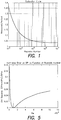
- the calibration curve shown in FIG. 1 illustrates the relationship between Reynolds number (Re) and the ratio of a measured velocity (V measured ; i.e., an uncompensated velocity reported by a flow velocity meter) to an actual velocity (V actual ; i.e., the volumetrically averaged flow velocity) for a given fluid flow as determined by comparing the raw meter output to a calibrated reference flow velocity.
- V measured measured velocity
- V actual actual velocity
- V measured V actual 1 + c 0 + c 1 Re c 2
- a high Reynolds number approximation e.g., Re > 10 6
- a method for determining a parameter of fluid flow within a piping system includes the steps of: a) determining a measured velocity of the fluid flow within the piping system using a fluid flow meter; b) determining a measured difference in pressure value within the fluid flow using a differential pressure meter; c) selecting an estimated Reynolds number of the fluid flow; d) determining a calculated difference in pressure value using a model which relates the calculated difference in pressure value to the measured velocity and the estimated Reynolds number of the fluid flow; e) determining a degree of inaccuracy of the estimated Reynolds number using the measured difference in pressure and the calculated difference in pressure; and f) iteratively adjusting the estimated Reynolds number, determining the calculated difference in pressure, and determining the degree of inaccuracy using the adjusted Reynolds number, until the degree of inaccuracy is within an acceptable range.
- an apparatus for determining a parameter of fluid flow within a piping system includes a fluid flow meter, a differential pressure meter, and a processor.
- the fluid flow meter is operable to determine the velocity of the fluid flow within the piping system.
- the differential pressure meter is operable to determine a measured difference in pressure within the fluid flow within the piping system.
- the processor is adapted to receive input including an estimated Reynolds number of the fluid flow.
- the processor is further adapted to determine a calculated difference in pressure value using a model which relates the calculated difference in pressure value to a measured fluid flow velocity and the estimated Reynolds number of the fluid flow.
- the processor is further adapted to determine a degree of inaccuracy of the estimated Reynolds number using the measured difference in pressure and the calculated difference in pressure, and to iteratively adjust the estimated Reynolds number, determine the calculated difference in pressure steps, and determine the degree of inaccuracy until the degree of inaccuracy is within an acceptable range.
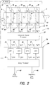
- the present invention provides both an apparatus and method for accurately determining flow parameters of fluid flows within a conduit (e.g., a pipe), and in particular high viscosity fluid flows, or fluid flows having a viscosity that varies over time, using a differential pressure meter 8 ("DP meter") and a fluid flow meter 10.
- a conduit e.g., a pipe
- DP meter differential pressure meter 8
- fluid flow meter 10 e.g., a pipe
- the conduit is referred to as a pipe.
- the present invention is not limited to sensing fluid flow within a pipe, however.
- the DP meter 8 may include any type of meter that can determine a differential pressure ( ⁇ P) in the fluid flow.
- the DP meter 8 may include a first pressure transducer 9 operable to measure the pressure of the fluid flow at a first position along the axial length of the pipe 14 and a second pressure transducer 11 operable to measure the pressure at a second position axial position, where a fixed geometry of pipe 14 having a axial length "L" is disposed between the two positions.
- the fluid flow meter 10 is operable to determine the velocity of the fluid flow within the pipe ("V measured ").
- An example of an acceptable fluid flow meter is the SONAR fluid flow meter described in U.S. Patent No. 7,389,187 entitled “Apparatus and Method for Using an Array of Ultrasonic Sensors for Determining the Velocity of a Fluid Within a Pipe", which patent is hereby incorporated by reference in its entirety.
- the fluid flow meter example described in the '187 Patent will be at least partially described herein. The present invention is not limited to using this fluid flow meter 10, or any other particular fluid flow meter.
- the fluid flow meter 10 includes a sensing device 16 comprising an array of ultrasonic sensor units 18-21.
- Each sensor unit comprises a pair of ultrasonic sensors 40,42, one of which functions as a transmitter (Tx) 40 and the other as a receiver (Rx) 42.
- the sensor units 18-21 are spaced axially along the outer surface 22 of a pipe 14 having a process flow 12 propagating therein.
- the sensors 40,42 within each pair are diametrically disposed on the pipe 14 at predetermined locations along the pipe to provide a through transmission configuration, such that the sensors transmit and receive an ultrasonic signal that propagates through the fluid substantially orthogonal to the direction of the flow of the fluid within the pipe.
- the flow meter 10 is not limited to this particular transmitter/receiver configuration.
- each pair of ultrasonic sensors 40,42 measures a transit time (i.e., time of flight (TOF), or phase modulation) of an ultrasonic signal propagating through the fluid 12 from the transmitting sensor 40 to the receiving sensor 42.
- the transit time measurement or variation is indicative of one or more coherent properties that convect with the flow within the pipe (e.g., vortical disturbances, inhomogenieties within the flow, temperature variations, bubbles, particles, pressure disturbances), which are indicative of the velocity of the process flow 12.
- the ultrasonic sensors may operate at a variety of different frequencies. There is, however, likely an optimum sensor frequency range associated with the particular application at hand.
- Examples of frequencies used for a flow meter embodying the present invention used in oil and gas applications are 1 MHz and 5 MHz.
- the ultrasonic sensors may also provide a pulsed, chirped or continuous signal through the fluid flow 12.
- An example of the sensors 40,42 that may be used are Model no. 113-241-591, manufactured by Krautkramer.
- An ultrasonic signal processor 37 fires the sensors 40 in response to a firing signal 39 from the transmitter 24 and receives the ultrasonic output signals S 1 (t) - S N (t) from the sensors 42.
- the signal processor 37 processes the data from each of the sensor units 18-21 to provide an analog or digital output signal T 1 (t) - T N (t) indicative of the time of flight or transit time of the ultrasonic signal through the fluid.
- the signal processor 37 may also provide an output signal indicative of the amplitude (or attenuation) of the ultrasonic signals.
- One such signal processor is model no. USPC 2100 manufactured by Krautkramer Ultrasonic Systems.
- the output signals (T 1 (t)- T N (t)) of the ultrasonic signal processor 37 are provided to the processor 24, which processes the transit time measurement data to determine one or both of the flow velocity and the volumetric flow rate.
- the transit time is defined as the time it takes for an ultrasonic signal to propagate from the transmitting sensor 40 to the respective receiving sensor 42 through the pipe wall and the fluid 12.
- the effect of the vortical disturbances (and/or other inhomogenities within the fluid) on the transit time of the ultrasonic signal is to delay or speed up the transit time. Therefore, each sensing unit 18-21 provides a respective output signal T 1 (t)-T N (t) indicative of the variations in the transit time of the ultrasonic signals propagating orthogonal to the direction of the fluid 12.
- the present invention does not require the processor 24 be adapted to any particular signal processing technique, and therefore known techniques such as k- ⁇ plot, cross-correlation, etc., can be used and will not be further described herein.
- the processor 24 is adapted to determine an initial flow velocity value (V measured ) and difference in pressure within the fluid flow (DP measured ), using the fluid flow meter and the DP meter, respectively.
- the processor is adapted to receive an estimated Reynolds number (Re est ) that is selected by the end user to be appropriate for the flow application / piping system at hand.
- FIG. 4 diagrammatically illustrates the Darcy Friction Factor as a function of the Reynolds number for a fluid flow.
- the Darcy Friction Factor relates the pressure loss due to friction along a given length of pipe to the average velocity of the pipe.
- the Haaland Equation is an example of an expression relating the friction factor of the piping system, the relative wall roughness of the piping system ( ⁇ /D), and the Reynolds number of the fluid flow.
- the present invention is not limited to this expression and alternative expressions can be used to relate the friction factor of the pipe to the Reynolds number of the fluid flow (e.g., Colebrook Equation, etc.).
- the processor is further adapted to calculate a difference in pressure (DP calculated ) using the measured fluid flow velocity within the piping system, and the determined Darcy Friction Factor ( ⁇ ).
- DP calculated a difference in pressure
- the processor is adapted to use the calculated difference in pressure (DP calculated ) and the difference in pressure measured within the fluid flow (DP measured ) to determine a degree of inaccuracy of the estimated Reynolds number (Re est ). Any difference between the calculated difference in pressure (DP calculated ) and the measured difference in pressure (DP measured) can then be evaluated to determine whether it is within an acceptable predetermined range.
- the exact values of the error range will depend upon the application at hand; e.g., the type of fluid flow, viscosity and velocity of the fluid, etc.
- the evaluation may utilize an error function that indicates the degree of inaccuracy of the estimated Reynolds number.
- the error function which can be referred to as "Chi 2 ", is not limited to any particular expression.
- a Reynolds number for the fluid flow within the piping system with an acceptable accuracy is determined under the present invention by iteratively performing the process described above; i.e., updating the estimated Reynolds number each time and using it to determine the Darcy Friction Factor and the calculated difference in pressure (DP calculated ) until the difference between the last Re est and the current Re est is within an acceptable error range.
- the iterative process is diagrammatically illustrated in FIG. 3 .
- FIG. 5 graphically illustrates an error function versus Reynolds number.
- the present invention apparatus and methodology enables the determination of an accurate Reynolds number value for fluid flows having a low Reynolds number, and also for fluid flows having a Reynolds number that varies during operation of the piping system.
- An advantage of having an accurate Reynolds number is that fluid flow parameters (e.g., velocity, flow rate, viscosity, etc.) can be more accurately determined than would be typically possible using an assumed or static Reynolds number.
Landscapes
- Physics & Mathematics (AREA)
- Fluid Mechanics (AREA)
- General Physics & Mathematics (AREA)
- Electromagnetism (AREA)
- Acoustics & Sound (AREA)
- Measuring Volume Flow (AREA)
Claims (12)
- Verfahren zum Bestimmen eines Parameters einer Fluidströmung in einem Rohrleitungssystem, das folgende Schritte aufweist:Bestimmen einer gemessenen Geschwindigkeit der Fluidströmung in dem Rohrleitungssystem unter Verwendung eines Fluiddurchflussmessers;Bestimmen einer gemessenen Differenz beim Druckwert innerhalb der Fluidströmung unter Verwendung eines Differenzdruckmessers;Auswählen einer geschätzten Reynolds-Zahl der Fluidströmung;Bestimmen einer berechneten Differenz im Druckwert unter Verwendung eines Modells, das die berechnete Differenz im Druckwert zu der gemessenen Geschwindigkeit und der geschätzten Reynolds-Zahl der Fluidströmung in Beziehung setzt;Bestimmen eines Grades der Ungenauigkeit der geschätzten Reynolds-Zahl unter Verwendung der gemessenen Druckdifferenz und der berechneten Druckdifferenz; unditeratives Anpassen der geschätzten Reynolds-Zahl, Bestimmen der berechneten Druckdifferenz und Bestimmen des Grades der Ungenauigkeit unter Verwendung der angepassten Reynolds-Zahl, bis der Grad der Ungenauigkeit innerhalb einer akzeptablen Spanne liegt.
- Verfahren nach Anspruch 1,
wobei der Schritt des Bestimmens der gemessenen Geschwindigkeit unter Verwendung eines Fluiddurchflussmessers mit Ultraschallsensoren ausgeführt wird. - Verfahren nach Anspruch 2,
das ferner den Schritt des Bestimmens der Geschwindigkeit der Fluidströmung unter Verwendung der angepassten geschätzten Reynolds-Zahl beinhaltet. - Verfahren nach Anspruch 3,
wobei der Schritt des Bestimmens eines Grades der Ungenauigkeit der geschätzten Reynolds-Zahl das Verwenden einer Fehlerfunktion beinhaltet, die gemessene Druckdifferenz und die berechnete Druckdifferenz beinhaltet. - Verfahren nach Anspruch 1,
wobei der Schritt des Bestimmens der gemessenen Differenz beim Druckwert innerhalb der Fluidströmung ausgeführt wird unter Verwendung eines ersten Druckwandlers, der sich in einer ersten axialen Position an dem Rohrleitungssystem befindet, und eines zweiten Druckwandlers, der sich in einer zweiten axialen Position an dem Rohrleitungssystem befindet, wobei die erste und die zweite axiale Position axial voneinander getrennt sind. - Verfahren nach Anspruch 5,
wobei der Fluiddurchflussmesser an dem Rohrleitungssystem zwischen der ersten und der zweiten axialen Position angeordnet ist. - Vorrichtung zum Bestimmen eines Parameters einer Fluidströmung in einem Rohrleitungssystem, aufweisend:einen Fluiddurchflussmesser, der betriebsmäßig dazu ausgebildet ist, die Geschwindigkeit der Fluidströmung in dem Rohrleitungssystem zu bestimmen;ein Differenzdruck-Messgerät, das betriebsmäßig dazu ausgebildet ist, eine gemessene Druckdifferenz in der Fluidströmung in dem Rohrleitungssystem zu bestimmen;einen Prozessor, der ausgebildet ist zum Empfangen eines Eingangssignals, das eine geschätzte Reynolds-Zahl der Fluidströmung beinhaltet, und zum Bestimmen einer berechneten Differenz im Druckwert unter Verwendung eines Modells, das die berechnete Differenz im Druckwert zu einer gemessenen Fluidströmungsgeschwindigkeit und der geschätzten Reynolds-Zahl der Fluidströmung in Beziehung setzt, sowie zum Bestimmen eines Grades der Ungenauigkeit der geschätzten Reynolds-Zahl unter Verwendung der gemessenen Druckdifferenz und der berechneten Druckdifferenz, und zum iterativen Anpassen der geschätzten Reynolds-Zahl, Bestimmen der berechneten Druckdifferenz und Bestimmen des Grades der Ungenauigkeit, bis der Grad der Ungenauigkeit innerhalb einer akzeptablen Spanne liegt.
- Vorrichtung nach Anspruch 7,
wobei der Fluiddurchflussmesser betriebsmäßig dazu ausgebildet ist, die Fluidströmungsgeschwindigkeit unter Verwendung von Ultraschallsensoren zu messen. - Vorrichtung nach Anspruch 8,
wobei der Prozessor dazu ausgebildet ist, die Geschwindigkeit der Fluidströmung unter Verwendung der angepassten Reynolds-Zahl zu bestimmen. - Vorrichtung nach Anspruch 9,
wobei der Prozessor dazu ausgebildet ist, den Grad der Ungenauigkeit der geschätzten Reynolds-Zahl unter Verwendung einer Fehlerfunktion zu bestimmen, die die gemessene Druckdifferenz und die berechnete Druckdifferenz beinhaltet. - Vorrichtung nach Anspruch 7,
wobei der Differenzdruckmesser einen ersten Druckwandler, der sich an einer ersten axialen Position an dem Rohrleitungssystem anordnen lässt, und einen zweiten Druckwandler beinhaltet, der sich an einer zweiten axialen Position an dem Rohrleitungssystem anordnen lässt, wobei die erste und zweite axial Position axial voneinander getrennt sind. - Vorrichtung nach Anspruch 11,
wobei der Fluiddurchflussmesser derart bemessen ist, dass er sich an dem Rohrleitungssystem zwischen der ersten und der zweiten axialen Position anordnen lässt.
Applications Claiming Priority (2)
| Application Number | Priority Date | Filing Date | Title |
|---|---|---|---|
| US10375408P | 2008-10-08 | 2008-10-08 | |
| PCT/US2009/059992 WO2010042713A1 (en) | 2008-10-08 | 2009-10-08 | Viscous fluid flow measurement using a differential pressure measurement and a sonar measured velocity |
Publications (2)
| Publication Number | Publication Date |
|---|---|
| EP2350575A1 EP2350575A1 (de) | 2011-08-03 |
| EP2350575B1 true EP2350575B1 (de) | 2017-01-18 |
Family
ID=41665112
Family Applications (1)
| Application Number | Title | Priority Date | Filing Date |
|---|---|---|---|
| EP09740574.0A Active EP2350575B1 (de) | 2008-10-08 | 2009-10-08 | Messung des flusses viskoser flüssigkeiten unter verwendung einer differenzdruckmessung und einer sonargemessenen geschwindigkeit |
Country Status (5)
| Country | Link |
|---|---|
| US (1) | US8428892B2 (de) |
| EP (1) | EP2350575B1 (de) |
| AU (1) | AU2009302284B2 (de) |
| CA (1) | CA2739100C (de) |
| WO (1) | WO2010042713A1 (de) |
Families Citing this family (15)
| Publication number | Priority date | Publication date | Assignee | Title |
|---|---|---|---|---|
| CA2785919C (en) * | 2009-12-31 | 2016-05-24 | Endress+Hauser Flowtec Ag | Measuring system having a measuring transducer of vibration-type |
| JP5477051B2 (ja) * | 2010-03-01 | 2014-04-23 | 株式会社デンソー | 超音波流量計 |
| CA2823688C (en) | 2010-12-07 | 2019-10-01 | Expro Meters, Inc. | Method for in-situ calibrating a differential pressure plus sonar flow meter system using dry gas conditions |
| DE102011080365A1 (de) * | 2011-08-03 | 2013-02-07 | Endress + Hauser Flowtec Ag | Verfahren zum Ermitteln des Durchflusses mittels Ultraschall |
| AU2013331272B2 (en) | 2012-10-16 | 2016-12-22 | Expro Meters, Inc. | Systems and methods for managing hydrocarbon material producing wellsites using clamp-on flow meters |
| NO20131320A1 (no) * | 2013-10-01 | 2015-04-02 | Fmc Kongsberg Subsea As | Fremgangsmåte og apparat for måling av individuelle komponenter i et flerfasefluid |
| NO344565B1 (no) * | 2013-10-01 | 2020-02-03 | Fmc Kongsberg Subsea As | Fremgangsmåte og apparat for måling av individuelle komponenter i et flerfasefluid |
| CN103913202B (zh) * | 2014-04-14 | 2017-09-19 | 姜跃炜 | 超声波水表截取系数处理方法 |
| US10101194B2 (en) | 2015-12-31 | 2018-10-16 | General Electric Company | System and method for identifying and recovering from a temporary sensor failure |
| US10401207B2 (en) | 2016-09-14 | 2019-09-03 | GE Oil & Gas UK, Ltd. | Method for assessing and managing sensor uncertainties in a virtual flow meter |
| US11940318B2 (en) | 2016-09-27 | 2024-03-26 | Baker Hughes Energy Technology UK Limited | Method for detection and isolation of faulty sensors |
| BR112019009095A2 (pt) * | 2016-11-04 | 2019-07-16 | Univ Coventry | métodos de monitorar fluxo de fluido, de calibração de um medidor de fluxo de pressão diferencial, aparelhos para monitorar fluxo de fluido, e, de calibração para calibrar um medidor de fluxo de pressão diferencial |
| EP3704449A1 (de) * | 2017-10-31 | 2020-09-09 | ABB Schweiz AG | Erweiterter durchflussmesser mit einem system zur simulation von fluidparametern |
| CN113432680B (zh) * | 2021-06-08 | 2023-09-01 | 中广核工程有限公司 | 一种核电厂反应堆冷却剂系统流量标定方法 |
| CN118050058B (zh) * | 2024-04-16 | 2024-06-14 | 海默新宸水下技术(上海)有限公司 | 螺旋节流件流量计量方法 |
Family Cites Families (11)
| Publication number | Priority date | Publication date | Assignee | Title |
|---|---|---|---|---|
| US6151557A (en) | 1998-01-13 | 2000-11-21 | Rosemount Inc. | Friction flowmeter with improved software |
| US6422092B1 (en) * | 1998-09-10 | 2002-07-23 | The Texas A&M University System | Multiple-phase flow meter |
| US6352001B1 (en) | 1999-08-30 | 2002-03-05 | General Electric Company | Non-iterative method for obtaining mass flow rate |
| AU2003295992A1 (en) * | 2002-11-22 | 2004-06-18 | Cidra Corporation | Method for calibrating a flow meter having an array of sensors |
| CA2513248C (en) | 2003-01-13 | 2013-01-08 | Cidra Corporation | Apparatus and method using an array of ultrasonic sensors for determining the velocity of a fluid within a pipe |
| US7047822B2 (en) * | 2004-09-13 | 2006-05-23 | Veris, Inc. | Devices, installations and methods for improved fluid flow measurement in a conduit |
| US7000463B1 (en) * | 2004-11-12 | 2006-02-21 | Mks Instruments, Inc. | Reynolds number correction function for mass flow rate sensor |
| US8641813B2 (en) | 2005-07-07 | 2014-02-04 | Expro Meters, Inc. | System and method for optimizing a gas/liquid separation process |
| JP4858829B2 (ja) * | 2006-03-28 | 2012-01-18 | 横河電機株式会社 | マルチバリアブル質量流量伝送器システム |
| GB2453704B (en) | 2006-08-29 | 2011-11-02 | Richard Steven | Improvements in or relating to flow metering |
| WO2008030454A2 (en) * | 2006-09-05 | 2008-03-13 | Celerity, Inc. | Multi-gas flow device |
-
2009
- 2009-10-08 EP EP09740574.0A patent/EP2350575B1/de active Active
- 2009-10-08 WO PCT/US2009/059992 patent/WO2010042713A1/en not_active Ceased
- 2009-10-08 CA CA2739100A patent/CA2739100C/en active Active
- 2009-10-08 US US12/575,908 patent/US8428892B2/en active Active
- 2009-10-08 AU AU2009302284A patent/AU2009302284B2/en active Active
Non-Patent Citations (1)
| Title |
|---|
| None * |
Also Published As
| Publication number | Publication date |
|---|---|
| CA2739100C (en) | 2018-05-22 |
| US8428892B2 (en) | 2013-04-23 |
| AU2009302284B2 (en) | 2015-02-05 |
| EP2350575A1 (de) | 2011-08-03 |
| US20100094569A1 (en) | 2010-04-15 |
| AU2009302284A1 (en) | 2010-04-15 |
| CA2739100A1 (en) | 2010-04-15 |
| WO2010042713A1 (en) | 2010-04-15 |
Similar Documents
| Publication | Publication Date | Title |
|---|---|---|
| US8428892B2 (en) | Viscous fluid flow measurement using a differential pressure measurement and a SONAR measured velocity | |
| EP2435799B1 (de) | Verfahren und vorrichtung zur überwachung eines mehrphasigen flüssigkeitsstroms | |
| EP2100103B1 (de) | Ultraschallströmungsmesser mit simultanen flugzeit- und dopplerverfahren | |
| EP2203721B1 (de) | Verfahren und system für den nachweis von ablagerungen in einem ultraschallströmungsmesser | |
| RU2303242C2 (ru) | Способ и устройство для определения реологических параметров жидкости | |
| US10627272B2 (en) | Method and apparatus for monitoring multiphase fluid flow | |
| EP3535551B1 (de) | Verbesserungen an oder im zusammenhang mit der überwachung eines fluidstroms | |
| EP2283329B1 (de) | Verfahren zur erzeugung einer diagnostik aus einer abweichung eines strömungsmesserparameters | |
| US9435681B2 (en) | Method for in-situ calibrating a differential pressure plus sonar flow meter system using dry gas conditions | |
| NO20171056A1 (en) | Ultrasonic viscometer |
Legal Events
| Date | Code | Title | Description |
|---|---|---|---|
| PUAI | Public reference made under article 153(3) epc to a published international application that has entered the european phase |
Free format text: ORIGINAL CODE: 0009012 |
|
| 17P | Request for examination filed |
Effective date: 20110503 |
|
| AK | Designated contracting states |
Kind code of ref document: A1 Designated state(s): AT BE BG CH CY CZ DE DK EE ES FI FR GB GR HR HU IE IS IT LI LT LU LV MC MK MT NL NO PL PT RO SE SI SK SM TR |
|
| DAX | Request for extension of the european patent (deleted) | ||
| GRAP | Despatch of communication of intention to grant a patent |
Free format text: ORIGINAL CODE: EPIDOSNIGR1 |
|
| INTG | Intention to grant announced |
Effective date: 20161004 |
|
| GRAS | Grant fee paid |
Free format text: ORIGINAL CODE: EPIDOSNIGR3 |
|
| GRAA | (expected) grant |
Free format text: ORIGINAL CODE: 0009210 |
|
| AK | Designated contracting states |
Kind code of ref document: B1 Designated state(s): AT BE BG CH CY CZ DE DK EE ES FI FR GB GR HR HU IE IS IT LI LT LU LV MC MK MT NL NO PL PT RO SE SI SK SM TR |
|
| REG | Reference to a national code |
Ref country code: GB Ref legal event code: FG4D |
|
| REG | Reference to a national code |
Ref country code: CH Ref legal event code: EP |
|
| REG | Reference to a national code |
Ref country code: AT Ref legal event code: REF Ref document number: 863173 Country of ref document: AT Kind code of ref document: T Effective date: 20170215 |
|
| REG | Reference to a national code |
Ref country code: IE Ref legal event code: FG4D |
|
| REG | Reference to a national code |
Ref country code: DE Ref legal event code: R096 Ref document number: 602009043836 Country of ref document: DE |
|
| REG | Reference to a national code |
Ref country code: NL Ref legal event code: MP Effective date: 20170118 |
|
| REG | Reference to a national code |
Ref country code: LT Ref legal event code: MG4D |
|
| REG | Reference to a national code |
Ref country code: NO Ref legal event code: T2 Effective date: 20170118 |
|
| REG | Reference to a national code |
Ref country code: AT Ref legal event code: MK05 Ref document number: 863173 Country of ref document: AT Kind code of ref document: T Effective date: 20170118 |
|
| PG25 | Lapsed in a contracting state [announced via postgrant information from national office to epo] |
Ref country code: NL Free format text: LAPSE BECAUSE OF FAILURE TO SUBMIT A TRANSLATION OF THE DESCRIPTION OR TO PAY THE FEE WITHIN THE PRESCRIBED TIME-LIMIT Effective date: 20170118 |
|
| PG25 | Lapsed in a contracting state [announced via postgrant information from national office to epo] |
Ref country code: FI Free format text: LAPSE BECAUSE OF FAILURE TO SUBMIT A TRANSLATION OF THE DESCRIPTION OR TO PAY THE FEE WITHIN THE PRESCRIBED TIME-LIMIT Effective date: 20170118 Ref country code: GR Free format text: LAPSE BECAUSE OF FAILURE TO SUBMIT A TRANSLATION OF THE DESCRIPTION OR TO PAY THE FEE WITHIN THE PRESCRIBED TIME-LIMIT Effective date: 20170419 Ref country code: HR Free format text: LAPSE BECAUSE OF FAILURE TO SUBMIT A TRANSLATION OF THE DESCRIPTION OR TO PAY THE FEE WITHIN THE PRESCRIBED TIME-LIMIT Effective date: 20170118 Ref country code: LT Free format text: LAPSE BECAUSE OF FAILURE TO SUBMIT A TRANSLATION OF THE DESCRIPTION OR TO PAY THE FEE WITHIN THE PRESCRIBED TIME-LIMIT Effective date: 20170118 Ref country code: IS Free format text: LAPSE BECAUSE OF FAILURE TO SUBMIT A TRANSLATION OF THE DESCRIPTION OR TO PAY THE FEE WITHIN THE PRESCRIBED TIME-LIMIT Effective date: 20170518 |
|
| PG25 | Lapsed in a contracting state [announced via postgrant information from national office to epo] |
Ref country code: ES Free format text: LAPSE BECAUSE OF FAILURE TO SUBMIT A TRANSLATION OF THE DESCRIPTION OR TO PAY THE FEE WITHIN THE PRESCRIBED TIME-LIMIT Effective date: 20170118 Ref country code: LV Free format text: LAPSE BECAUSE OF FAILURE TO SUBMIT A TRANSLATION OF THE DESCRIPTION OR TO PAY THE FEE WITHIN THE PRESCRIBED TIME-LIMIT Effective date: 20170118 Ref country code: PL Free format text: LAPSE BECAUSE OF FAILURE TO SUBMIT A TRANSLATION OF THE DESCRIPTION OR TO PAY THE FEE WITHIN THE PRESCRIBED TIME-LIMIT Effective date: 20170118 Ref country code: PT Free format text: LAPSE BECAUSE OF FAILURE TO SUBMIT A TRANSLATION OF THE DESCRIPTION OR TO PAY THE FEE WITHIN THE PRESCRIBED TIME-LIMIT Effective date: 20170518 Ref country code: SE Free format text: LAPSE BECAUSE OF FAILURE TO SUBMIT A TRANSLATION OF THE DESCRIPTION OR TO PAY THE FEE WITHIN THE PRESCRIBED TIME-LIMIT Effective date: 20170118 Ref country code: BG Free format text: LAPSE BECAUSE OF FAILURE TO SUBMIT A TRANSLATION OF THE DESCRIPTION OR TO PAY THE FEE WITHIN THE PRESCRIBED TIME-LIMIT Effective date: 20170418 Ref country code: AT Free format text: LAPSE BECAUSE OF FAILURE TO SUBMIT A TRANSLATION OF THE DESCRIPTION OR TO PAY THE FEE WITHIN THE PRESCRIBED TIME-LIMIT Effective date: 20170118 |
|
| REG | Reference to a national code |
Ref country code: DE Ref legal event code: R097 Ref document number: 602009043836 Country of ref document: DE |
|
| PG25 | Lapsed in a contracting state [announced via postgrant information from national office to epo] |
Ref country code: SK Free format text: LAPSE BECAUSE OF FAILURE TO SUBMIT A TRANSLATION OF THE DESCRIPTION OR TO PAY THE FEE WITHIN THE PRESCRIBED TIME-LIMIT Effective date: 20170118 Ref country code: CZ Free format text: LAPSE BECAUSE OF FAILURE TO SUBMIT A TRANSLATION OF THE DESCRIPTION OR TO PAY THE FEE WITHIN THE PRESCRIBED TIME-LIMIT Effective date: 20170118 Ref country code: RO Free format text: LAPSE BECAUSE OF FAILURE TO SUBMIT A TRANSLATION OF THE DESCRIPTION OR TO PAY THE FEE WITHIN THE PRESCRIBED TIME-LIMIT Effective date: 20170118 Ref country code: EE Free format text: LAPSE BECAUSE OF FAILURE TO SUBMIT A TRANSLATION OF THE DESCRIPTION OR TO PAY THE FEE WITHIN THE PRESCRIBED TIME-LIMIT Effective date: 20170118 Ref country code: IT Free format text: LAPSE BECAUSE OF FAILURE TO SUBMIT A TRANSLATION OF THE DESCRIPTION OR TO PAY THE FEE WITHIN THE PRESCRIBED TIME-LIMIT Effective date: 20170118 |
|
| PLBE | No opposition filed within time limit |
Free format text: ORIGINAL CODE: 0009261 |
|
| STAA | Information on the status of an ep patent application or granted ep patent |
Free format text: STATUS: NO OPPOSITION FILED WITHIN TIME LIMIT |
|
| PG25 | Lapsed in a contracting state [announced via postgrant information from national office to epo] |
Ref country code: SM Free format text: LAPSE BECAUSE OF FAILURE TO SUBMIT A TRANSLATION OF THE DESCRIPTION OR TO PAY THE FEE WITHIN THE PRESCRIBED TIME-LIMIT Effective date: 20170118 Ref country code: DK Free format text: LAPSE BECAUSE OF FAILURE TO SUBMIT A TRANSLATION OF THE DESCRIPTION OR TO PAY THE FEE WITHIN THE PRESCRIBED TIME-LIMIT Effective date: 20170118 |
|
| 26N | No opposition filed |
Effective date: 20171019 |
|
| PG25 | Lapsed in a contracting state [announced via postgrant information from national office to epo] |
Ref country code: SI Free format text: LAPSE BECAUSE OF FAILURE TO SUBMIT A TRANSLATION OF THE DESCRIPTION OR TO PAY THE FEE WITHIN THE PRESCRIBED TIME-LIMIT Effective date: 20170118 |
|
| REG | Reference to a national code |
Ref country code: DE Ref legal event code: R119 Ref document number: 602009043836 Country of ref document: DE |
|
| PG25 | Lapsed in a contracting state [announced via postgrant information from national office to epo] |
Ref country code: MC Free format text: LAPSE BECAUSE OF FAILURE TO SUBMIT A TRANSLATION OF THE DESCRIPTION OR TO PAY THE FEE WITHIN THE PRESCRIBED TIME-LIMIT Effective date: 20170118 |
|
| REG | Reference to a national code |
Ref country code: CH Ref legal event code: PL |
|
| REG | Reference to a national code |
Ref country code: IE Ref legal event code: MM4A |
|
| REG | Reference to a national code |
Ref country code: FR Ref legal event code: ST Effective date: 20180629 |
|
| PG25 | Lapsed in a contracting state [announced via postgrant information from national office to epo] |
Ref country code: LU Free format text: LAPSE BECAUSE OF NON-PAYMENT OF DUE FEES Effective date: 20171008 Ref country code: CH Free format text: LAPSE BECAUSE OF NON-PAYMENT OF DUE FEES Effective date: 20171031 Ref country code: DE Free format text: LAPSE BECAUSE OF NON-PAYMENT OF DUE FEES Effective date: 20180501 Ref country code: LI Free format text: LAPSE BECAUSE OF NON-PAYMENT OF DUE FEES Effective date: 20171031 |
|
| REG | Reference to a national code |
Ref country code: BE Ref legal event code: MM Effective date: 20171031 |
|
| PG25 | Lapsed in a contracting state [announced via postgrant information from national office to epo] |
Ref country code: BE Free format text: LAPSE BECAUSE OF NON-PAYMENT OF DUE FEES Effective date: 20171031 Ref country code: FR Free format text: LAPSE BECAUSE OF NON-PAYMENT OF DUE FEES Effective date: 20171031 |
|
| PG25 | Lapsed in a contracting state [announced via postgrant information from national office to epo] |
Ref country code: MT Free format text: LAPSE BECAUSE OF NON-PAYMENT OF DUE FEES Effective date: 20171008 |
|
| PG25 | Lapsed in a contracting state [announced via postgrant information from national office to epo] |
Ref country code: IE Free format text: LAPSE BECAUSE OF NON-PAYMENT OF DUE FEES Effective date: 20171008 |
|
| PG25 | Lapsed in a contracting state [announced via postgrant information from national office to epo] |
Ref country code: HU Free format text: LAPSE BECAUSE OF FAILURE TO SUBMIT A TRANSLATION OF THE DESCRIPTION OR TO PAY THE FEE WITHIN THE PRESCRIBED TIME-LIMIT; INVALID AB INITIO Effective date: 20091008 |
|
| PG25 | Lapsed in a contracting state [announced via postgrant information from national office to epo] |
Ref country code: CY Free format text: LAPSE BECAUSE OF NON-PAYMENT OF DUE FEES Effective date: 20170118 |
|
| PG25 | Lapsed in a contracting state [announced via postgrant information from national office to epo] |
Ref country code: MK Free format text: LAPSE BECAUSE OF FAILURE TO SUBMIT A TRANSLATION OF THE DESCRIPTION OR TO PAY THE FEE WITHIN THE PRESCRIBED TIME-LIMIT Effective date: 20170118 |
|
| PG25 | Lapsed in a contracting state [announced via postgrant information from national office to epo] |
Ref country code: TR Free format text: LAPSE BECAUSE OF FAILURE TO SUBMIT A TRANSLATION OF THE DESCRIPTION OR TO PAY THE FEE WITHIN THE PRESCRIBED TIME-LIMIT Effective date: 20170118 |
|
| P01 | Opt-out of the competence of the unified patent court (upc) registered |
Effective date: 20230512 |
|
| PGFP | Annual fee paid to national office [announced via postgrant information from national office to epo] |
Ref country code: GB Payment date: 20250904 Year of fee payment: 17 |
|
| PGFP | Annual fee paid to national office [announced via postgrant information from national office to epo] |
Ref country code: NO Payment date: 20251009 Year of fee payment: 17 |