EP2351191B2 - Ringgenerator - Google Patents
Ringgenerator Download PDFInfo
- Publication number
- EP2351191B2 EP2351191B2 EP09737382.3A EP09737382A EP2351191B2 EP 2351191 B2 EP2351191 B2 EP 2351191B2 EP 09737382 A EP09737382 A EP 09737382A EP 2351191 B2 EP2351191 B2 EP 2351191B2
- Authority
- EP
- European Patent Office
- Prior art keywords
- stator
- ring
- cooling
- ring generator
- wind
- Prior art date
- Legal status (The legal status is an assumption and is not a legal conclusion. Google has not performed a legal analysis and makes no representation as to the accuracy of the status listed.)
- Active
Links
Images


Classifications
-
- F—MECHANICAL ENGINEERING; LIGHTING; HEATING; WEAPONS; BLASTING
- F03—MACHINES OR ENGINES FOR LIQUIDS; WIND, SPRING, OR WEIGHT MOTORS; PRODUCING MECHANICAL POWER OR A REACTIVE PROPULSIVE THRUST, NOT OTHERWISE PROVIDED FOR
- F03D—WIND MOTORS
- F03D80/00—Details, components or accessories not provided for in groups F03D1/00 - F03D17/00
- F03D80/60—Cooling or heating of wind motors
-
- F—MECHANICAL ENGINEERING; LIGHTING; HEATING; WEAPONS; BLASTING
- F03—MACHINES OR ENGINES FOR LIQUIDS; WIND, SPRING, OR WEIGHT MOTORS; PRODUCING MECHANICAL POWER OR A REACTIVE PROPULSIVE THRUST, NOT OTHERWISE PROVIDED FOR
- F03D—WIND MOTORS
- F03D17/00—Monitoring or testing of wind motors, e.g. diagnostics
- F03D17/007—Wind farm monitoring
-
- F—MECHANICAL ENGINEERING; LIGHTING; HEATING; WEAPONS; BLASTING
- F03—MACHINES OR ENGINES FOR LIQUIDS; WIND, SPRING, OR WEIGHT MOTORS; PRODUCING MECHANICAL POWER OR A REACTIVE PROPULSIVE THRUST, NOT OTHERWISE PROVIDED FOR
- F03D—WIND MOTORS
- F03D80/00—Details, components or accessories not provided for in groups F03D1/00 - F03D17/00
- F03D80/60—Cooling or heating of wind motors
- F03D80/601—Cooling or heating of wind motors using ambient airflow; Convective cooling of components
-
- F—MECHANICAL ENGINEERING; LIGHTING; HEATING; WEAPONS; BLASTING
- F03—MACHINES OR ENGINES FOR LIQUIDS; WIND, SPRING, OR WEIGHT MOTORS; PRODUCING MECHANICAL POWER OR A REACTIVE PROPULSIVE THRUST, NOT OTHERWISE PROVIDED FOR
- F03D—WIND MOTORS
- F03D9/00—Adaptations of wind motors for special use; Combinations of wind motors with apparatus driven thereby; Wind motors specially adapted for installation in particular locations
- F03D9/20—Wind motors characterised by the driven apparatus
- F03D9/25—Wind motors characterised by the driven apparatus the apparatus being an electrical generator
- F03D9/255—Wind motors characterised by the driven apparatus the apparatus being an electrical generator connected to electrical distribution networks; Arrangements therefor
- F03D9/257—Wind motors characterised by the driven apparatus the apparatus being an electrical generator connected to electrical distribution networks; Arrangements therefor the wind motor being part of a wind farm
-
- F—MECHANICAL ENGINEERING; LIGHTING; HEATING; WEAPONS; BLASTING
- F03—MACHINES OR ENGINES FOR LIQUIDS; WIND, SPRING, OR WEIGHT MOTORS; PRODUCING MECHANICAL POWER OR A REACTIVE PROPULSIVE THRUST, NOT OTHERWISE PROVIDED FOR
- F03D—WIND MOTORS
- F03D9/00—Adaptations of wind motors for special use; Combinations of wind motors with apparatus driven thereby; Wind motors specially adapted for installation in particular locations
- F03D9/30—Wind motors specially adapted for installation in particular locations
- F03D9/34—Wind motors specially adapted for installation in particular locations on stationary objects or on stationary man-made structures
-
- F—MECHANICAL ENGINEERING; LIGHTING; HEATING; WEAPONS; BLASTING
- F04—POSITIVE - DISPLACEMENT MACHINES FOR LIQUIDS; PUMPS FOR LIQUIDS OR ELASTIC FLUIDS
- F04D—NON-POSITIVE-DISPLACEMENT PUMPS
- F04D29/00—Details, component parts, or accessories
- F04D29/58—Cooling; Heating; Diminishing heat transfer
- F04D29/582—Cooling; Heating; Diminishing heat transfer specially adapted for elastic fluid pumps
-
- H—ELECTRICITY
- H02—GENERATION; CONVERSION OR DISTRIBUTION OF ELECTRIC POWER
- H02K—DYNAMO-ELECTRIC MACHINES
- H02K5/00—Casings; Enclosures; Supports
- H02K5/04—Casings or enclosures characterised by the shape, form or construction thereof
- H02K5/20—Casings or enclosures characterised by the shape, form or construction thereof with channels or ducts for flow of cooling medium
- H02K5/207—Casings or enclosures characterised by the shape, form or construction thereof with channels or ducts for flow of cooling medium with openings in the casing specially adapted for ambient air
-
- H—ELECTRICITY
- H02—GENERATION; CONVERSION OR DISTRIBUTION OF ELECTRIC POWER
- H02K—DYNAMO-ELECTRIC MACHINES
- H02K7/00—Arrangements for handling mechanical energy structurally associated with dynamo-electric machines, e.g. structural association with mechanical driving motors or auxiliary dynamo-electric machines
- H02K7/18—Structural association of electric generators with mechanical driving motors, e.g. with turbines
- H02K7/1807—Rotary generators
- H02K7/1823—Rotary generators structurally associated with turbines or similar engines
- H02K7/183—Rotary generators structurally associated with turbines or similar engines wherein the turbine is a wind turbine
- H02K7/1838—Generators mounted in a nacelle or similar structure of a horizontal axis wind turbine
-
- H—ELECTRICITY
- H02—GENERATION; CONVERSION OR DISTRIBUTION OF ELECTRIC POWER
- H02K—DYNAMO-ELECTRIC MACHINES
- H02K9/00—Arrangements for cooling or ventilating
- H02K9/02—Arrangements for cooling or ventilating by ambient air flowing through the machine
- H02K9/04—Arrangements for cooling or ventilating by ambient air flowing through the machine having means for generating a flow of cooling medium
-
- H—ELECTRICITY
- H02—GENERATION; CONVERSION OR DISTRIBUTION OF ELECTRIC POWER
- H02K—DYNAMO-ELECTRIC MACHINES
- H02K9/00—Arrangements for cooling or ventilating
- H02K9/14—Arrangements for cooling or ventilating wherein gaseous cooling medium circulates between the machine casing and a surrounding mantle
- H02K9/18—Arrangements for cooling or ventilating wherein gaseous cooling medium circulates between the machine casing and a surrounding mantle wherein the external part of the closed circuit comprises a heat exchanger structurally associated with the machine casing
-
- Y—GENERAL TAGGING OF NEW TECHNOLOGICAL DEVELOPMENTS; GENERAL TAGGING OF CROSS-SECTIONAL TECHNOLOGIES SPANNING OVER SEVERAL SECTIONS OF THE IPC; TECHNICAL SUBJECTS COVERED BY FORMER USPC CROSS-REFERENCE ART COLLECTIONS [XRACs] AND DIGESTS
- Y02—TECHNOLOGIES OR APPLICATIONS FOR MITIGATION OR ADAPTATION AGAINST CLIMATE CHANGE
- Y02E—REDUCTION OF GREENHOUSE GAS [GHG] EMISSIONS, RELATED TO ENERGY GENERATION, TRANSMISSION OR DISTRIBUTION
- Y02E10/00—Energy generation through renewable energy sources
- Y02E10/70—Wind energy
- Y02E10/72—Wind turbines with rotation axis in wind direction
Definitions
- the present invention relates to a ring generator of a wind turbine. Furthermore, the present invention relates to a method for controlling a wind turbine and the present invention relates to a wind turbine.
- a wind turbine converts mechanical work taken from the wind into electrical energy using an electrical generator.
- a ring generator is a slowly rotating generator that does not need a gear between the rotor of the generator and the mechanical rotor, which has rotor blades.
- the ring generator has a large number of poles. The number can range from 20 to 84 poles and beyond.
- the ring generator has a relatively large diameter compared to its axial extent.
- the ring generator of a modern wind turbine of 7 or more megawatts nominal power has a diameter at the air gap of approximately 10 m, whereas the expansion of the air gap in the axial direction is in the range of 1 m.
- the air gap is known to be the space between the stator and the rotor of an electrical generator.
- the rotor and / or the stator essentially take the form of a ring, which should be the reason for the designation ring generator.
- a generator for gearless wind converters is known as an external rotor.
- the entire magnetically active part of the generator is arranged outside a nacelle.
- an external rotor is specifically proposed, in which the rotor is arranged outside the stator in a radial view. Support arms lead from the bearing arranged inside the stator to the rotor arranged outside. These carrier arms of the rotor are designed as blades at the same time in order to convey cooling air into the cooling channels of the stator.
- Such a structure is extremely complicated and time-consuming.
- the stator in particular the stator ring, can be prepared for water cooling, in particular for guiding a water flow.
- the disadvantage here is that there is a fundamental risk of corrosion due to the use of water cooling, in particular for a metallic object such as the stator ring.
- the object of the present invention was therefore to improve a ring generator as much as possible, in particular to increase the cooling of a ring generator and / or to make it more efficient, or at least to propose an alternative ring generator.
- a ring generator according to claim 1 is proposed.
- a ring generator for a better understanding of the invention is first described, which does not form the invention, but is an example that facilitates the understanding of the invention.
- Such a ring generator of a wind power plant which converts mechanical work taken from the wind into electrical energy, has a stator and a rotor, which is rotatable relative to the stator about an axis of rotation.
- the term rotor instead of rotor is used here in order to rule out any confusion with the mechanical rotor of a wind energy installation, which is essentially formed from a rotor hub and at least one, usually three rotor blades.
- the use of the term runner should in no way give an indication of the type of generator used.
- a synchronous generator is preferably used.
- the stator essentially has a circumferential stator ring for receiving a laminated core with stator windings.
- a rotary movement of the rotor relative to the stator excites an alternating magnetic field in the laminated core, which in turn leads to a current flow in the stator windings and, due to losses, results in the stator being heated.
- the stator ring has cooling channels for cooling the stator by an air flow. Additional air cooling is thus prepared.
- Such cooling channels can be provided both for active cooling and for passive cooling, or for a combination of both. In the case of active cooling, an artificial air flow for cooling is generated.
- This ring generator is designed as an internal rotor. Accordingly, the rotor runs within the stator.
- the air gap between the rotor and the stator is essentially designed as a - short - cylinder jacket. This would also include an arrangement in which the air gap slightly in the axial direction has decreasing or increasing diameter and thus resembles a cone section.
- the rotor is arranged as a ring in the radial direction within the stator, which is also annular.
- the stator is fixed as an outer ring.
- At least some cooling channels are prepared for active cooling by a forced air flow and, alternatively or at the same time, some cooling channels are prepared for passive cooling by the wind.
- a device is provided which generates an air flow and the relevant cooling channels for active cooling have an opening for inflowing or outflowing the relevant air flow.
- Some cooling channels can preferably be prepared for active and others for passive cooling.
- a ring generator with a stator bell connected to the stator is proposed for creating a pressure chamber with an overpressure or underpressure for providing an active air flow through and / or along the stator and / or rotor for cooling the ring generator.
- Such a stator bell thus includes an area adjacent to and adjacent to the ring generator, in which an overpressure is generated from air and this air can escape through sections in the ring generator, in particular through cooling channels in the stator ring and / or through the air gap, so that a cooling Airflow is created.
- the stator bell has a circumferential, in particular circular fastening section for fastening to the stator, in particular to the stator ring. Otherwise, the exact shape of the stator bell does not really matter.
- the stator ring has an inner ring section for active cooling and an outer ring section for passive cooling with respect to the axis of rotation, and the stator bell is fastened to the stator ring in such a way that only the inner ring section is flowed against by the active cooling air flow.
- the stator bell is fastened with respect to the radial direction in a circular fastening section between the inner and the outer ring section.
- the inner ring section is thus essentially exposed within the stator bell and thus the pressure chamber of the stator bell, whereas the outer ring section is arranged outside the stator bell. An air flow generated by the pressure chamber in the stator bell thus only reaches the inner ring section.
- an air vacuum can also be generated in the stator bell in order to draw air through openings in the ring generator to the stator bell.
- the stator bell is preferably prepared to carry the stator ring, which in turn carries the laminated core with the stator windings.
- the stator bell can be fastened to the stator ring and to a machine carrier in the wind energy installation.
- the stator ring would be attached to the machine carrier via the stator bell.
- the stator bell is not limited to a bell-shaped configuration, but can also take a general hood shape or the like.
- At least one blower opening with a blower is provided in the stator bell.
- a blower can blow air into the pressure chamber in order to generate an air flow through and / or along the stator and / or rotor for cooling the ring generator.
- a blower can also create an air vacuum in the pressure chamber in order to generate an opposite air flow.
- two or more fans can be provided in the stator bell.
- Some or all of the cooling channels preferably run axially to the axis of rotation.
- the ring generator is thus at least partially prepared for cooling air flows in the axial direction.
- a plurality of cooling channels is preferably arranged concentrically around the axis of rotation and forms at least one annular cooling area.
- the ring generator is characterized in that the stator ring has an inner and an outer and optionally a central, stabilizing support ring with respect to the axis of rotation in the radial direction, a circular cooling area being formed between two support rings.
- the stator ring is thus divided into stabilizing and cooling areas.
- At least two support rings are formed, between which a cooling area, which is also essentially ring-shaped, is formed.
- two annular cooling areas can also be provided, namely one between the central and outer support ring or the other between the central and inner support ring.
- the support rings are each essentially solid.
- the laminated core or other magnetically highly conductive areas are also attached to the inner support ring.
- the two or three support rings mentioned are preferred and, in particular, are manufactured in one piece, such as cast, together with the cooling regions arranged between them.
- the support rings which could also be referred to as support ring sections, are essentially intended to stiffen the stator ring.
- the stator bell is favorably attached to the middle, stabilizing support ring, whereby the stator ring can be carried by the stator bell.
- the stator bell engages the middle support ring for carrying on the stator ring.
- Different cooling stages and temperature ranges are created by using three support rings and a total of two annular cooling regions arranged between them.
- An inner annular cooling area is closer to the laminated core and thus the heat source and becomes correspondingly higher temperatures have as the corresponding outer annular cooling region. Any stresses that can occur due to the high temperature in the inner annular cooling area can be absorbed by the outer annular cooling area. Accordingly, a lot of heat and a relatively large expansion would be expected in the inner annular cooling area, whereas in the outer annular cooling area little heat and correspondingly smaller expansion would be expected.
- the outer annular region holds the inner annular region and, if necessary, limits its expansion.
- adjacent cooling channels of a cooling area are delimited from one another by boundary walls and the boundary walls form connecting webs between two adjacent stabilizing support rings and / or two adjacent support rings are connected to one another by cooling fins.
- Such connecting structures or connecting webs can simultaneously fulfill the function of cooling fins.
- these inner cooling fins can have any shape. In addition to a straight version, S-shaped, curved and other shapes are also possible.
- At least one, preferably all, of the cooling channels of at least one cooling area have a triangular shape in the axial cross section and / or two adjacent cooling channels each form the shape of a parallelogram, in particular a rhombus, in the axial cross section, and / or the cooling channels at least one to the inside of the cooling channel have facing cooling fin.
- a triangular shape results in a simple and at the same time stable design option.
- the provision of cooling fins in the inside of the cooling channel allows cooling by an air flow through the cooling channel in question.
- the stator ring is segmented, in particular composed of two, three, four or more essentially symmetrical circular segments.
- the stator ring can be composed of three 120 ° segments.
- Such segments are fundamentally easier to manufacture and / or to transport.
- handling can be considerably simplified by segmentation.
- the stator ring is made of aluminum and / or an aluminum alloy at least in the area of the cooling channels and / or is cast from a material.
- Aluminum has a high temperature conductivity and is therefore preferably provided in the area of the cooling channels and thus in cooling areas.
- aluminum is fundamentally corrosion-resistant and can therefore also be provided for contact with moist outside air or the like.
- An alloy can be used to influence properties of the material, particularly with regard to thermal conductivity, corrosion resistance and stability.
- the stator ring, or a portion thereof, is preferably cast from one material. This should create special channel designs and other shapes easily and reproducibly.
- the casting of the relevant section can be provided at least in the area of the cooling channels and / or the or some support rings.
- a segmentation can also be carried out, for example, by casting individual segments such as 90 ° or 120 ° segments.
- a further embodiment proposes that passive cooling channels are provided, each with an inflow opening pointing in the axial direction and an outflow opening pointing at least partially radially outwards.
- passive cooling channels can thus be flowed against in the axial direction, for example, by wind, as a result of which the wind flows into the inflow openings and at least partially flows out again radially outward from the passive cooling channels.
- a suction effect can be achieved through the radially outward-pointing outflow openings.
- the fact that the passive cooling channels have an inflow and an outflow opening and are thus designed as partially closed channels enables the stability of the stator ring to be increased. Basically, the outflow openings can also point in the axial direction.
- the outflow opening is thus preferably provided as a suction opening.
- This effect can preferably be further enhanced or enhanced by the stator ring having a curved surface in the axial direction in the region of the outflow opening.
- a convex curvature can create a suction effect similar to an aircraft wing, which could thus act on the outlet opening and increase the air flow through the passive cooling channel.
- the ring generator has a stator ring for receiving stator windings and a rotor rotatably mounted relative to the stator. Furthermore, a stator bell connected to the stator ring is provided, which creates a pressure chamber with overpressure or underpressure for providing an air flow through the stator and / or rotor for cooling the ring generator, the stator bell having at least one blower opening provided with the blower and the blower is movably mounted by means of a movement mechanism or by a quick release device is attached to temporarily open the blower opening for maintenance purposes and / or to pass through for one person.
- the stator bell is thus attached to the stator ring and an excess pressure is generated in the stator bell adjacent to the stator rotor arrangement by the at least one fan, which overpressure escapes as air cooling flow or air cooling flows through openings in the rotor stator arrangement, such as through the air gap.
- at least one fan is movably supported by means of a movement mechanism. This fan can thus be folded away, pivoted away, pushed away, turned away or moved in some other way, so that the corresponding fan opening in the stator bell is cleared and is thus free for maintenance purposes and / or for one person to pass through. The fan in question and any other fans are of course switched off for such maintenance purposes.
- the movement mechanism is preferably designed as a swivel mechanism.
- the blower can thus be pivoted away from its blower opening in a simple manner and only needs to be locked in the open or closed position in each case.
- the ring generator is characterized in that the stator bell has a first fastening section for fastening to a machine carrier of a wind power installation and has a plurality of support sections, in particular support arms, which extend outward in a star-shaped arrangement to a second fastening section for fastening to the stator ring, so that the stator ring can be carried on the machine sections via the support sections.
- the first fastening section is thus an internally arranged section and the second fastening section is an outer fastening section.
- the support sections, in particular support arms extend in a star shape from the inner to the outer support section and thereby essentially span the stator bell.
- connection areas are provided between the support sections or support arms in order to close the stator bell.
- Fan openings with fans can be provided in particular in these connection areas.
- the intermediate areas also stabilize, the support sections or support arms essentially take over the holding of the stator ring.
- the stator bell can thus perform two functions at the same time, namely to carry the stator ring and at the same time to delimit a pressure chamber with an overpressure or underpressure to provide an airflow.
- increased torsional rigidity can be achieved through the intermediate areas.
- the stator bell is preferably cast from one piece, preferably from a metal, in particular cast iron, preferably from cast iron with spheroidal graphite, which is also known as spheroidal graphite cast iron or is abbreviated as GJS or formerly GGG - which means globular gray cast iron.
- a metal in particular cast iron, preferably from cast iron with spheroidal graphite, which is also known as spheroidal graphite cast iron or is abbreviated as GJS or formerly GGG - which means globular gray cast iron.
- a ring generator can basically have any of the features described and any combination of features is possible in principle.
- a ring generator with a stator bell with a movably mounted fan can be combined with features of a ring generator which has a stator ring with cooling channels for cooling the stator by at least one air flow.
- a ring generator with a stator ring with cooling channels with features of a ring generator with a stator bell can be combined with a movably mounted fan.
- This possible combination also relates to the further features described according to one or more embodiments.
- the ring generator preferably has a nominal output of at least 30 kW, preferably at least 300 kW and even more preferably at least 1 MW.
- the rated power of the ring generator is therefore suitable for use in modern wind turbines.
- a method for controlling a wind energy installation according to claim 7 is proposed.
- a wind turbine to be controlled has a ring generator with a rotor and a stator.
- an electrical power generated by the ring generator is recorded.
- This detection can be carried out by a direct power measurement, for example on the stator windings, or an indirect measurement can be carried out using characteristic measured values, such as measuring the speed and / or the angle of attack of the rotor blades and / or internal arithmetic variables, which a control computer has available anyway.
- a temperature measurement can also provide information about the electrical power generated.
- At least one blower installed in a stator bell is turned on to generate air flow through and / or along the stator and / or rotor to cool the ring generator when the sensed electrical power reaches and / or exceeds a predetermined value.
- active cooling which requires additional energy, is only used if corresponding power losses and therefore corresponding thermal loads are to be expected due to the electrical power generated.
- control of the wind energy installation is otherwise carried out in a manner known to the person skilled in the art.
- a value of or above 30%, preferably 50% and more preferably 80% of the rated power of the wind power installation is preferably defined as the predetermined value.
- the nominal power itself is chosen as the predetermined value. Accordingly, the active cooling is only switched on at full load or shortly before it, and may not be actively felt at partial load.
- control method according to the invention is preferably used for one of the ring generators according to the invention and / or for a ring generator according to at least one of the described embodiments.
- a wind power plant with a nacelle and one of the ring generators according to the invention is also proposed, in particular according to one of the described embodiments.
- a wind power installation is preferably characterized in that the ring generator is arranged inside the nacelle except for an outer section of the stator ring and the outer section of the stator ring is arranged outside the nacelle in order to be blown against by wind.
- the nacelle also contains the hub cladding, which rotates with the rotor when the wind turbine is in operation.
- the hub cover is also known as a spinner.
- the ring generator is thus essentially protected in the nacelle and thus from the weather.
- the ring generator can already be cooled passively or actively within the nacelle, for example by cooling channels and / or by using a corresponding stator bell.
- an outer section of the stator ring in particular with a passive cooling area, be arranged outside the nacelle.
- a ring section projecting slightly beyond the nacelle cladding, which can be flown against for cooling wind.
- the wind can flow around the gondola to cool the generator directly. The cooling effect depends at least in part on the prevailing wind speed. High cooling is thus achieved in the full load range when there is strong wind, whereas less cooling is achieved in the partial load range and thus in the case of weak winds, and the cooling is therefore automatically at least partially adapted to requirements.
- An outer section of the stator ring preferably has coolants, in particular cooling channels for passive cooling, these coolants being directly exposed to the wind.
- the ring generator can thus emit heat directly into the wind from which it is blown. It is pointed out that such a situation generally relates to a wind energy plant that is in operation and that is turned into the wind.
- the nacelle is aerodynamically designed to be flowed in a substantially laminar manner by the wind, provided that it is turned into the wind, in order to also have wind in the region of an outer section of the stator ring.
- Such an aerodynamic configuration can be achieved, for example, by an essentially approximately teardrop-shaped, egg-shaped and / or oval shape in a side view and / or by an essentially rotationally symmetrical shape with respect to the rotor axis.
- a baffle for guiding the wind or shaping a fluid similar to a wind tunnel can be provided.
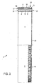
- the stator ring 2 is ring-shaped and forms part of a ring generator with an internal rotor.
- the stator ring 2 has an inner support ring 4, a central support ring 6 and an outer support ring 8.
- An activated cooling section 10 is provided between the inner and outer support rings 4, 6 and a passive cooling section 12 is provided between the middle and outer support rings 6, 8.
- the stator ring 2 as shown, including the inner, middle and outer support rings 4, 6, 8 and active and passive cooling section 10, 12, is cast in one piece, using aluminum as the material.
- the inner, middle and outer support ring 4, 6, 8 ensure stability and rigidity due to their essentially solid design.
- a corresponding laminated core carrying stator windings and having a good magnetic conductivity must be arranged on the inside of the inner support ring 4. Due to its attachment to the inner support ring 4, the laminated core can be firmly carried. Within this laminated core, an internal rotor is then intended to be rotatably mounted relative to the stator. Heat from the laminated core can be given off directly to the surrounding air, but will mainly give off heat to the active cooling section 10 and the passive cooling section 12 via the support ring 4.
- the active cooling section then has a multiplicity of active cooling channels 14 for emitting heat, which are essentially triangular in shape in the active cooling section 10 between the inner and middle support rings 4, 6. Further heat can be emitted via the passive cooling channels 16, which are approximately square or trapezoidal in cross section.
- the stator ring 2 has an outer diameter of approximately 5 m.
- the axial extent is about 90 cm.
- the passive cooling channels 16 each have a radially outward opening, so that in the rear view according to FIG Fig. 2 only the active cooling channels 14 can be seen.
- the cut area shows the shape of the active and passive cooling channels 14, 16 in an axial section.
- the active cooling channels run essentially axially from an inlet area 22 to an outlet area 24.
- the passive cooling channel 14 runs from an inflow opening 17 to the outflow opening 18.
- the passive cooling channel 16 also runs essentially in the axial direction, the outflow opening being directed radially outward is.
- the inlet area 22 of the active cooling duct 14 is located on the side of the stator ring 2 opposite the inflow opening 17 of the passive cooling duct 16.
- the stator ring 2 is accordingly also prepared for an active air flow through the active cooling ducts 14 to essentially result in a passive air flow through the passive cooling channels 16 is directed opposite.
- the active cooling channels 14 are essentially triangular in cross-section, whereby they are arranged alternately with different orientations, so that two adjacent active cooling channels 14 together take on the shape of a parallelogram in cross-section.
- a boundary wall is arranged between two active cooling channels, two boundary walls 26 of an active cooling channel 14 always being inclined towards one another.
- the boundary walls 26 thus divide the active cooling channels 14 against one another and thus simultaneously serve as cooling fins. They also lead to a stable arrangement, in particular a stable connection of the inner support ring 4 with the central support ring 6 due to the mutually inclined arrangement.
- the cooling fins 28 thus increase the cooling surface in the active cooling channel 14 without significantly impeding an air flow.
- inner support ring bores 34 are provided on the inner support ring for fastening purposes.
- middle support ring bores 36 are provided in the area of the middle support ring 6 and in the area of the passive cooling section 12 adjacent to the outer support ring 8, the stator ring 2 has outer support ring bores 38. At least some of the holes 34, 36 and 38 are threaded and can be used for fastening purposes.
- the outer support ring bores 38 serve to fasten the stator ring 2 to a stator bell.
- the central support ring bores 36 are provided at some points on the stator ring by auxiliary surfaces 35, namely three bores at four points. They are used to attach cables.
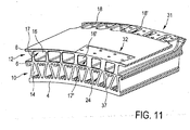
- Fig. 7 shows in a cross section how a passive cooling channel 16 is arranged between the outer support ring 8 and the central support ring 6.
- the passive cooling duct 16 extends from the inflow opening 17 to the outflow opening 18.
- An air flow can therefore flow essentially in the axial direction through the inlet opening 17 and at the end flow out through the radially outward opening 18.
- a side of the outer support ring 8 facing away from the passive cooling channel 16 is an outer side 30 of the stator ring 2. In accordance with the intended purpose, air therefore flows along both sides of the outer support ring 8, namely inside through the active cooling channel 16 and outside along the outer side 30.
- the active cooling channel 14 is formed between the middle support ring 6 and the inner support ring 4. It extends from the inlet area 22 to the outlet area 24.
- the middle support ring 6 also has blind holes 37, which are used to fasten a rain gutter.
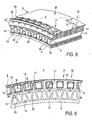
- FIG. 8 The perspective view of the Fig. 8 illustrates lee and luv side outer mounting areas 31 and 32, which are only partially shown and below with reference to FIG Fig. 12 are explained in more detail.
- Fig. 8 it can be seen how the passive cooling channels 16 open to the outside 30 through their outflow openings 18. Because the outflow openings 18 are directed radially outward, an end section 40, in which the outer supporting ring bores 38 are arranged, is formed behind the passive cooling channels 16, as seen from the intended wind direction.
- the Fig. 9 offers a direct view of the inflow openings 17 of the passive cooling channels 16. It is, as already in FIG Fig. 7 , to recognize that the passive cooling channels 16 taper slightly from the inflow opening 17. This can favor the inflow of wind into the inlet openings 17.
- the passive cooling channels can be designed as somewhat smaller passive cooling channels 16 'with correspondingly smaller inflow openings 17' in order to create somewhat more solid intermediate walls 19 'for drilling holes, in particular with threads.
- the intermediate walls 19, which have no bores, can be made somewhat narrower in order to create more space for a larger passive cooling channel 16.
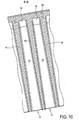
- the sectional view according to Fig. 10 offers a view of cut-open passive cooling channels 16.
- the tapering of the passive cooling channels from the inflow opening 17 to the outflow openings 18 is also illustrated again. Accordingly, the thickness of the partition walls 18 increases in the same direction.
- the external fastening areas 31 and 32 are each provided at two opposite points on the stator ring 2, that is to say offset by 180 °, as shown in FIG Fig. 1 can be recognized by the 2 by 3 somewhat reduced inflow openings 17 'in the 12 o'clock and 6 o'clock positions.
- a top view of one point is in the Fig. 12 is shown, according to which the leeward outer fastening area 31 has eight leeward holes 41, whereas the windward outer fastening area 32 has eight windward holes 42.
- the stator bell 100 of the 13 to 15 comprises a machine carrier fastening 102, a stator ring fastening 104 and an axle journal fastening 106.
- the machine carrier fastening 102, the stator ring fastening 104 and the axle journal fastening 102 are each designed as a circular fastening flange, each with one or two circumferential perforated rings.
- Six support sections 108 extend from the machine support attachment 102 approximately in a star shape to the stator ring attachment 104.
- the support sections 108 are designed as support arms 108 in order to absorb the weight of a stator attached to the stator ring attachment 104 and to be able to transmit it to a machine support via the machine support attachment 102.
- the areas between the support sections 108 are each spanned by sheet-like sections, with fan openings 110 being provided in each case. In some support sections 108 are also Auxiliary openings 112 are formed.
- axle pin fastening 106 there is an opening in the area of the axle pin fastening 106, which, however, is closed by an axle pin being fastened as intended.
- the entire stator bell 100 can thus be closed.
- a pressure space can be formed between this stator and rotor on the one hand and the stator bell 100 on the other hand and pressure can be applied to it.
- the air can then escape through openings in the rotor-stator arrangement, such as for example the air gap, and in the process leads to an air flow in the relevant, open areas.
- Fig. 16 shows the stator bell 100 together with a stator ring 2 *, which is fastened to the stator ring fastening 104 on the stator bell 100.
- a blower 114 is arranged in each blower opening 110 and, together with a blower cover 116, covers and closes the blower opening 110.
- blowers 114 By starting up one or more of the blowers 114, air is blown into the space enclosed or covered by the stator bell 100.
- the air can escape through openings in the generator, of which the stator ring 2 * forms part, and provide cooling.
- the auxiliary openings 112 are also closed with a cover, which in the Fig. 16 but is not shown in detail.
- fans 114 could also operate to draw air out of the space covered by stator bell 100, according to FIG Fig. 16 essentially to the right out of the drawing level.
- air is blown into the covered space, which, when the stator bell 100 is arranged as intended, originates from a corresponding gondola and, compared to outside air from the outside of the gondola, leads to better purity and dryness.
- Fig. 17 illustrates how the fan openings 110 can be used for maintenance or other purposes.
- the fan 114 is folded away by means of a hinge and the fan opening 110 is opened accordingly.
- the blower opening 110 opened in this way, a person can now get through the stator bell 100 through the blower opening 110 to the ring generator arranged behind it.
- a different movement mechanism can be provided for the fan 114 instead of a hinge for folding.
- a quick release fastener can also be used in a simple manner to open a blower opening 110. For this purpose, such a quick-action lock can be released in a few simple steps and the corresponding blower 114 can be removed.
- Fig. 18 explains schematically the overall concept according to the invention using an exemplary embodiment.
- Fig. 18 shows a side sectional view of a section of a nacelle 250 with a rotor 252 with rotor blades 254, a ring generator 200 with a rotor 201 and a stator 203 with a stator ring 202 and a laminated core 205 with stator windings 207, which are only indicated schematically.
- An air gap 209 is arranged between the stator 203 and the rotor 201.
- the stator ring 202 has an inner support ring 204, a central support ring 206 and an outer support ring 208.
- Passive cooling channels 216 are provided between the inner and outer support rings 206, 208, which form a passive cooling section 212.
- Active cooling channels 214 are arranged between the inner support ring 204 and the central support ring 206 and form an active cooling section 210.
- a stator bell 260 is fastened in the region of the central support ring 206 and a separating section 262 is provided following the magnetically active part of the rotor 201.
- Blowers 264 are arranged in the stator bell 260, which lead to overpressure in the pressure chamber 266, which is essentially arranged between the stator bell 260 and the separating section 262. Due to the pressure built up in the pressure chamber 266, air flows through the air gap 209 and the active cooling channels 214. The generator, in particular the stator, is thus cooled by the air flow 270 through the air gap 209 and the active cooling channels 214.
- the ring generator 200 up to and including the active cooling section 210 is thus arranged within the nacelle 250.
- the probe cover 251 * is lowered in one area and thus at the same height as the central support ring 206.
- the hub cover can be at the level of the outer support ring 208, as in FIG Fig. 18 is shown by reference numeral 251 **.
- the Fig. 18 so far shows a snapshot. It should be noted that on the stator ring 202 in the area of the middle support ring 206 on the side towards the hub cover 251 *, a rain gutter can be installed in order to prevent the entry of rain water in the area and thus to protect the elements of the ring generator 200 arranged inside the nacelle from rain water,
- the wind then passes from the area of the lower-drawn hub cladding 251 * into the area of the inflow openings 217 and to the passive and thus outer cooling section 212 and can flow there through the inflow openings 217 into the passive cooling channels 216 and cool the stator ring 202 in this area.
- blower 264 results in an active cooling flow 270 that flows through the air gap 209 and the active cooling channels 214.
- the wind leads to a passive cooling flow 272 that flows through the passive cooling channels 216.
- the active cooling flow 270 is opposite to the direction of the passive cooling flow 272.
- the fan (s) 264 presses air from the interior of the nacelle 253 through the stator bell 260 into the pressure chamber 266 and from there through the air gap 209 and the active cooling channels 214 towards the outside towards the rotor hub 256 and thus against the wind.
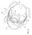
- the representations according to the 19 to 22 schematically show a nacelle 250.
- a tower, rotor blades and any nacelle structures such as an anemometer or the like are not shown or are only shown in the beginning.
- the perspective according to Fig. 19 diagonally from the front towards the nacelle 250 essentially shows the nacelle cover 251 and the hub cover 251 * and 251 **.
- a part of the rim of the outlet openings 218 and inlet openings 217 of the passive cooling section 212 can be seen.
- Fig. 19 diagonally from the front towards the nacelle 250 essentially shows the nacelle cover 251 and the hub cover 251 * and 251 **.
- the wind thus comes as intended from the right into the plane of the drawing, flows along the hub cladding 251 into the inflow openings 217 through passive cooling channels in the passive cooling section 212 and leaves the passive cooling section 212 again in the area of the outflow openings 218.
- the wind flows as intended in an axial direction Direction into the inflow openings 217, while he leaves the outflow opening 218 at least partially directed outwards in the radial direction.
- rotor blade extensions 274 can be seen on the hub cover 251 * or 251 **.
- Nearby is - in Fig. 19 , in particular in the rotor shoulder 274 shown on the left, a transition edge 276 between the higher area of the hub cover 251 ** and the lower area of the hub cover 251 * can be seen.
- the higher hub cover area 251 ** is approximately aligned with the outer support ring 208 and thus covers the inflow openings 217.
- the lower area of the hub cover 251 * is approximately aligned with the middle support ring 206, so that the inflow openings 217 can be seen in the area in question and also from Wind can be reached.
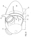
- nacelle 250 From the frontal view of the nacelle 250 according to Fig. 20 essentially the hub cover 251 * or 251 ** and the inflow openings 217 can be seen.
- the perspective according to Fig. 20 corresponds to the intended inflow direction by the wind.
- the windward outer fastening area 232 is arranged in the 12 o'clock position.
- nacelle-side rotor blade sections 278 can sweep over the area of the passive cooling section 212 and thereby the inflow openings 217 and outflow openings 218.
- Ring generator of a wind power plant with a stator with a circumferential stator ring for receiving a laminated core with stator windings and a rotor rotatably mounted about an axis of rotation relative to the stator, the ring generator being designed as an inner rotor and the stator ring having cooling channels for cooling the stator by an air stream.
- Ring generator according to embodiment 1, characterized in that at least some cooling channels for active cooling by a forced air flow and / or some cooling channels are prepared for passive cooling, in particular by the wind.
- Ring generator according to one of the preceding embodiments, further comprising a stator bell connected to the stator, in particular stator ring, for creating a pressure chamber with an overpressure or underpressure for providing an active air flow through and / or along the stator and / or rotor for cooling the ring generator.
- Ring generator characterized in that the stator ring has an inner ring section for active cooling and an outer ring section for passive cooling with respect to the axis of rotation, and that the stator bell is fastened to the stator ring in such a way that only the inner ring section is flown by the active cooling air flow becomes.
- Ring generator according to embodiment 3 or 4, characterized in that the stator bell is prepared to carry the stator ring.
- Ring generator according to one of the embodiments 3 to 5, characterized in that at least one blower opening with a blower is provided in the stator bell.
- Ring generator according to one of the preceding embodiments, characterized in that some or all of the cooling channels extend axially with respect to the axis of rotation.
- Ring generator according to one of the preceding embodiments, characterized in that a plurality of cooling channels are arranged concentrically around the axis of rotation and form at least one annular cooling area.
- stator ring based on the axis of rotation in the radial direction, has an inner and an outer and optionally a central, stabilizing support ring, an annular cooling region being formed at least between two support rings.
- Ring generator characterized in that the middle, stabilizing support ring is provided and that the or a stator bell is attached to the middle, stabilizing support ring and thereby the stator ring and thus the stator is carried by the stator bell.
- Ring generator according to embodiment 9 or 10, characterized in that adjacent cooling channels of a cooling area are delimited from one another by boundary walls and the boundary walls form connecting webs between two adjacent stabilizing support rings and / or two adjacent support rings are connected to one another by cooling fins.
- Ring generator according to one of the preceding embodiments, characterized in that at least one, preferably all, of the cooling channels of at least one cooling area have a triangular shape in axial cross section and / or two adjacent cooling channels each form the shape of a parallelogram in axial cross section and / or the cooling channels at least one Have a cooling fin facing the inside of the cooling channel.
- stator ring is segmented, in particular composed of two, three, four or more essentially symmetrical circular segments.
- stator ring is made of aluminum and / or an aluminum alloy at least in the region of the cooling channels and / or is cast from a material.
- Ring generator according to one of the preceding embodiments, characterized in that passive cooling channels are provided, each with an inflow opening pointing in the axial direction and an at least partially radially outward opening.
- Ring generator characterized in that the outflow opening is provided as a suction opening, so that a wind which flows axially from the outside of the stator ring generates a suction effect at the outflow opening and / or to favor a suction effect on the outflow opening of the stator ring in the axial direction in the region of the Outflow opening has a curved surface.
Landscapes
- Engineering & Computer Science (AREA)
- Power Engineering (AREA)
- Life Sciences & Earth Sciences (AREA)
- Sustainable Energy (AREA)
- Sustainable Development (AREA)
- General Engineering & Computer Science (AREA)
- Mechanical Engineering (AREA)
- Chemical & Material Sciences (AREA)
- Combustion & Propulsion (AREA)
- Thermal Sciences (AREA)
- Physics & Mathematics (AREA)
- Motor Or Generator Cooling System (AREA)
- Wind Motors (AREA)
- Saccharide Compounds (AREA)
- Nitrogen Condensed Heterocyclic Rings (AREA)
- Connection Of Motors, Electrical Generators, Mechanical Devices, And The Like (AREA)
Priority Applications (3)
| Application Number | Priority Date | Filing Date | Title |
|---|---|---|---|
| SI200930959T SI2351191T1 (sl) | 2008-10-08 | 2009-09-29 | Obročasti generator |
| PL09737382T PL2351191T3 (pl) | 2008-10-08 | 2009-09-29 | Generator pierścieniowy |
| CY20141100611T CY1115562T1 (el) | 2008-10-08 | 2014-08-06 | Δακτυλιοειδης γεννητρια |
Applications Claiming Priority (2)
| Application Number | Priority Date | Filing Date | Title |
|---|---|---|---|
| DE102008050848A DE102008050848A1 (de) | 2008-10-08 | 2008-10-08 | Ringgenerator |
| PCT/EP2009/062567 WO2010040659A2 (de) | 2008-10-08 | 2009-09-29 | Ringgenerator |
Publications (3)
| Publication Number | Publication Date |
|---|---|
| EP2351191A2 EP2351191A2 (de) | 2011-08-03 |
| EP2351191B1 EP2351191B1 (de) | 2014-05-21 |
| EP2351191B2 true EP2351191B2 (de) | 2020-05-13 |
Family
ID=41818782
Family Applications (1)
| Application Number | Title | Priority Date | Filing Date |
|---|---|---|---|
| EP09737382.3A Active EP2351191B2 (de) | 2008-10-08 | 2009-09-29 | Ringgenerator |
Country Status (21)
| Country | Link |
|---|---|
| US (2) | US20110260467A1 (pl) |
| EP (1) | EP2351191B2 (pl) |
| JP (2) | JP5453439B2 (pl) |
| KR (1) | KR101484917B1 (pl) |
| CN (1) | CN102246395B (pl) |
| AR (2) | AR073943A1 (pl) |
| AU (1) | AU2009301208B2 (pl) |
| BR (1) | BRPI0920394B1 (pl) |
| CA (1) | CA2739500C (pl) |
| CL (1) | CL2011000773A1 (pl) |
| CY (1) | CY1115562T1 (pl) |
| DE (1) | DE102008050848A1 (pl) |
| DK (1) | DK2351191T4 (pl) |
| ES (1) | ES2488816T3 (pl) |
| HR (1) | HRP20140683T1 (pl) |
| MX (1) | MX2011003642A (pl) |
| PL (1) | PL2351191T3 (pl) |
| PT (1) | PT2351191E (pl) |
| RU (1) | RU2506682C2 (pl) |
| SI (1) | SI2351191T1 (pl) |
| WO (1) | WO2010040659A2 (pl) |
Families Citing this family (39)
| Publication number | Priority date | Publication date | Assignee | Title |
|---|---|---|---|---|
| DE102008050848A1 (de) | 2008-10-08 | 2010-04-15 | Wobben, Aloys | Ringgenerator |
| PT2636131T (pt) | 2010-11-04 | 2020-04-24 | Wobben Properties Gmbh | Instalação de energia eólica com gerador síncrono bem como gerador síncrono de rotação lenta |
| EP2512007B1 (en) * | 2011-04-15 | 2019-06-05 | Siemens Gamesa Renewable Energy A/S | Access means for an electrical machine |
| GB2494925B (en) * | 2011-09-26 | 2013-09-18 | Sway Turbine As | Air cooling of wind turbine generator |
| EP2587052A1 (en) | 2011-10-25 | 2013-05-01 | Ewt Ip B.V. | Wind turbine with cooling system |
| WO2013111259A1 (ja) * | 2012-01-23 | 2013-08-01 | 株式会社日立製作所 | 風力発電設備 |
| DE102012208550A1 (de) * | 2012-05-22 | 2013-11-28 | Wobben Properties Gmbh | Generator einer getriebelosen Windenergieanlage |
| DE102012208547A1 (de) | 2012-05-22 | 2013-11-28 | Wobben Properties Gmbh | Synchrongenerator einer getriebelosen Windenergieanlage |
| DE102012208549A1 (de) * | 2012-05-22 | 2013-11-28 | Wobben Properties Gmbh | Optimierter Synchrongenerator einer getriebelosen Windenergieanlage |
| EP2736154A1 (en) * | 2012-11-21 | 2014-05-28 | Siemens Aktiengesellschaft | Dual stator permanent magnet generator for a wind turbine |
| JP2014140288A (ja) * | 2012-12-20 | 2014-07-31 | Yaskawa Electric Corp | 回転電機および回転電機の筐体 |
| EP2922179A1 (de) * | 2014-03-17 | 2015-09-23 | Siemens Aktiengesellschaft | Rotor einer rotierenden elektrischen Maschine |
| EP2924847A1 (de) * | 2014-03-28 | 2015-09-30 | Siemens Aktiengesellschaft | Zusammengesetzte elektrische Maschine |
| EP2993766A1 (de) * | 2014-09-08 | 2016-03-09 | Siemens Aktiengesellschaft | Verbesserte Kühlung eines Ringmotors |
| CN104882992A (zh) * | 2015-06-10 | 2015-09-02 | 常熟市第二特种电机有限公司 | 新型耐高温电机机壳 |
| DE102015210662A1 (de) * | 2015-06-11 | 2016-12-15 | Wobben Properties Gmbh | Statorring für einen elektrischen Generator, sowie Generator und Windenergieanlage mit selbigem |
| DE102015212452A1 (de) * | 2015-07-02 | 2017-01-05 | Wobben Properties Gmbh | Trägerelement, insbesondere Statorträger-Element und/oder Läuferträger-Element, System von Trägerelementen, Generatorträger, Generator, Generator-Tragsystem, Gondel einer Windenergieanlage, Windenergieanlage und Verfahren zur Montage eines Generator-Tragsystems |
| DE102015212453A1 (de) * | 2015-07-02 | 2017-01-05 | Wobben Properties Gmbh | Trägerelement, insbesondere Statorträger-Element und/oder Läuferträger-Element, System von Trägerelementen, Generatorträger, Generator, Generator-Tragsystem, Gondel einer Windenergieanlage, Windenergieanlage und Verfahren zur Montage eines Generator-Tragsystems |
| DE102015213514A1 (de) * | 2015-07-17 | 2017-01-19 | Wobben Properties Gmbh | Statorring, Generator, sowie Windenergieanlage mit selbigem |
| EP3226383A1 (en) | 2016-03-30 | 2017-10-04 | Siemens Aktiengesellschaft | Stator assembly for an electric generator with accommodation space |
| DE102016208051A1 (de) * | 2016-05-10 | 2017-11-16 | Wobben Properties Gmbh | Windenergieanlagen-Rotorblatt, und Windenergieanlage mit selbigem |
| DE102016108712A1 (de) | 2016-05-11 | 2017-11-16 | Wobben Properties Gmbh | Synchrongenerator einer getriebelosen Windenergieanlage sowie Verfahren zum Herstellen eines Synchrongenerators und Verwendung von Formspulen |
| RU169096U1 (ru) * | 2016-09-30 | 2017-03-03 | Федеральное государственное бюджетное образовательное учреждение высшего образования "Московский государственный технологический университет "СТАНКИН" (ФГБОУ ВО "МГТУ "СТАНКИН") | Охлаждаемый статор электрической машины |
| CN106401872A (zh) * | 2016-10-28 | 2017-02-15 | 陈晓东 | 具有环式电机的环罩风力发电机 |
| DE102016125218A1 (de) * | 2016-12-21 | 2018-06-21 | Wobben Properties Gmbh | Statorträger für einen Stator eines Windenergieanlagengenerators, sowie Stator, Generator und Windenergieanlage mit selbigem |
| CN106849467A (zh) * | 2016-12-30 | 2017-06-13 | 山东空能磁悬浮技术有限公司 | 一种制冷压缩机设备冷却结构 |
| DE102017119530A1 (de) * | 2017-08-25 | 2019-02-28 | Wobben Properties Gmbh | Generatorläufer und Generatorstator sowie Generator und Windenergieanlage damit und Verfahren zum Transportieren eines Generators |
| CN108843525B (zh) * | 2018-06-28 | 2020-07-28 | 十堰善新新能源科技有限公司 | 一种风力发电机组内壁散热装置 |
| CN109474113B (zh) * | 2018-09-06 | 2020-06-23 | 新疆金风科技股份有限公司 | 电机及风力发电机组 |
| CN109412339B (zh) * | 2018-09-06 | 2020-04-28 | 新疆金风科技股份有限公司 | 电机及风力发电机组 |
| RU2713452C1 (ru) * | 2019-02-06 | 2020-02-05 | Владимир Анатольевич Петров | Закрытая электрическая машина |
| RU2709622C1 (ru) * | 2019-02-06 | 2019-12-19 | Владимир Анатольевич Петров | Закрытая электрическая машина с внутренним неподвижным якорем |
| CN111864991B (zh) | 2019-04-30 | 2024-02-23 | 金风科技股份有限公司 | 冷却系统、电机及风力发电机组 |
| DE102019125467B4 (de) * | 2019-09-23 | 2022-12-29 | Christian Schrumpf | Flugwindkraftwerk |
| EP3809561A1 (en) * | 2019-10-18 | 2021-04-21 | Siemens Gamesa Renewable Energy A/S | Support structure for a generator of a wind turbine |
| DE102021107905A1 (de) * | 2021-03-29 | 2022-09-29 | Wobben Properties Gmbh | Luftkühlvorrichtung, Generator, Luftführungsvorrichtung, Windenergieanlage und Verfahren zur Herstellung eines Generators und einer Windenergieanlage |
| EP4102682A1 (en) * | 2021-06-09 | 2022-12-14 | Siemens Gamesa Renewable Energy A/S | Generator, wind turbine and method for cooling a direct drive generator of a wind turbine |
| EP4124752B1 (en) * | 2021-07-28 | 2025-04-30 | Siemens Gamesa Renewable Energy A/S | Wind turbine canopy with cooling fluid outlet |
| EP4266556A1 (en) * | 2022-04-22 | 2023-10-25 | Siemens Gamesa Renewable Energy A/S | Cooling circuit for an electric generator |
Citations (3)
| Publication number | Priority date | Publication date | Assignee | Title |
|---|---|---|---|---|
| SU1638769A1 (ru) † | 1989-04-24 | 1991-03-30 | Научно-исследовательский, проектно-конструкторский и технологический институт тяжелого электромашиностроения Харьковского завода "Электротяжмаш" им.В.И.Ленина | Закрыта электрическа машина |
| EP1218638A1 (en) † | 1999-09-24 | 2002-07-03 | Lagerwey Windturbine B.V. | Wind power generator |
| WO2010040659A2 (de) † | 2008-10-08 | 2010-04-15 | Wobben, Aloys | Ringgenerator |
Family Cites Families (40)
| Publication number | Priority date | Publication date | Assignee | Title |
|---|---|---|---|---|
| DE243208C (pl) | ||||
| US2810348A (en) * | 1954-12-08 | 1957-10-22 | Howard T White | Motor driven pump |
| FR1233089A (fr) * | 1959-04-29 | 1960-10-12 | Comp Generale Electricite | Dispositif de refroidissement pour machine électrique tournante |
| US3684906A (en) | 1971-03-26 | 1972-08-15 | Gen Electric | Castable rotor having radially venting laminations |
| US3916231A (en) | 1973-12-26 | 1975-10-28 | Marathon Letourneau Co | Induction motor |
| JPS5496707A (en) | 1978-01-17 | 1979-07-31 | Hitachi Ltd | Alternating current generator for automobile |
| US4370095A (en) * | 1980-11-03 | 1983-01-25 | Sleeper Jr H Prescott | Compound coaxial windmill |
| JPS5865977A (ja) | 1981-10-14 | 1983-04-19 | Hitachi Ltd | 風力発電装置の冷却機構 |
| JPS58127546A (ja) | 1982-01-20 | 1983-07-29 | Toshiba Corp | 回転電機の冷却外気清浄風洞 |
| JPS59222055A (ja) * | 1983-05-30 | 1984-12-13 | Fuji Electric Co Ltd | バルブ水車発電機 |
| US4631433A (en) * | 1985-05-06 | 1986-12-23 | General Electric Company | Plastic end shield with thermal barrier for dynamoelectric machines |
| DE4325372A1 (de) | 1993-07-23 | 1994-02-24 | Jaehnke Klaus Peter | Entlüftungskopf zu einem durch den Wind beweglichen Dachentlüfter ausgebildet |
| DE4331243A1 (de) | 1993-09-15 | 1995-03-16 | Abb Management Ag | Luftgekühlte rotierende elektrische Maschine |
| DE4431361A1 (de) | 1994-09-02 | 1996-03-07 | Jaehnke Klaus Peter | Windkraftmaschine |
| DE19608286B4 (de) * | 1996-02-23 | 2004-02-12 | Siemens Ag | Belüftungssystem für den Ringmotor einer Rohrmühle |
| DE19636591C2 (de) * | 1996-09-10 | 1999-12-09 | Friedrich Klinger | Synchrongenerator für einen getriebelosen Windenergiekonverter |
| JP2966799B2 (ja) * | 1996-11-07 | 1999-10-25 | ファナック株式会社 | 空冷式モータ |
| ES2156706B1 (es) * | 1999-02-09 | 2002-02-16 | Torres Martinez M | Perfeccionamientos en la estructura de aerogeneradores. |
| ATE250721T1 (de) | 1999-07-14 | 2003-10-15 | Aloys Wobben | Windenergieanlage mit einem geschlossenen kühlkreislauf |
| FR2797921B1 (fr) * | 1999-09-01 | 2001-09-28 | Alstom | Nacelle d'eolienne constituee par la carcasse d'un generateur electrique |
| US6278197B1 (en) | 2000-02-05 | 2001-08-21 | Kari Appa | Contra-rotating wind turbine system |
| JP3989693B2 (ja) * | 2000-04-28 | 2007-10-10 | 三菱電機株式会社 | 風力発電装置 |
| US6483199B2 (en) * | 2000-04-28 | 2002-11-19 | Mitsubishi Denki Kabushiki Kaisha | Wind power generating device |
| FR2810374B1 (fr) | 2000-06-19 | 2004-09-03 | Jeumont Ind | Dispositif de production de courant electrique a partir d'energie eolienne |
| SE525387C2 (sv) * | 2002-01-10 | 2005-02-08 | Swedish Vertical Wind Ab | Vertikalaxlat vindkraftaggregat och användning av detsamma |
| ES2206028B1 (es) | 2002-06-13 | 2005-03-01 | Manuel Torres Martinez | Perfeccionamientos en los aerogeneradores de produccion electrica. |
| ITMI20021439A1 (it) | 2002-06-28 | 2003-12-29 | High Technology Invest Bv | Impianto di generazione eolica ad alto rendimento energetico |
| DE10233947A1 (de) * | 2002-07-25 | 2004-02-12 | Siemens Ag | Windkraftanlage |
| DE10246690A1 (de) * | 2002-10-07 | 2004-04-22 | Siemens Ag | Belüftungssystem für Generatoren in Windkraftanlagen |
| ITTO20020908A1 (it) | 2002-10-17 | 2004-04-18 | Lorenzo Battisti | Sistema antighiaccio per impianti eolici. |
| JP2004260902A (ja) * | 2003-02-25 | 2004-09-16 | Kokusan Denki Co Ltd | 磁石発電機 |
| US7431567B1 (en) * | 2003-05-30 | 2008-10-07 | Northern Power Systems Inc. | Wind turbine having a direct-drive drivetrain |
| DE102004018758A1 (de) * | 2004-04-16 | 2005-11-03 | Klinger, Friedrich, Prof. Dr.-Ing. | Turmkopf einer Windenergieanlage |
| US7154193B2 (en) * | 2004-09-27 | 2006-12-26 | General Electric Company | Electrical machine with double-sided stator |
| DE102004064007B4 (de) * | 2004-09-24 | 2009-08-20 | Aloys Wobben | Windenergieanlage mit einer Generatorkühlung |
| US7548008B2 (en) * | 2004-09-27 | 2009-06-16 | General Electric Company | Electrical machine with double-sided lamination stack |
| US7427814B2 (en) * | 2006-03-22 | 2008-09-23 | General Electric Company | Wind turbine generators having wind assisted cooling systems and cooling methods |
| DE102006054807A1 (de) * | 2006-11-21 | 2008-06-05 | Siemens Ag | Elektromotor mit Schnellverschlusslüftereinheit |
| JP5050538B2 (ja) * | 2007-01-29 | 2012-10-17 | 株式会社明電舎 | モータの冷却構造 |
| ES2343447B1 (es) * | 2007-04-26 | 2011-05-20 | M.Torres Olvega Industrial, S.L. | Aerogenerador de alta produccion electrica. |
-
2008
- 2008-10-08 DE DE102008050848A patent/DE102008050848A1/de not_active Ceased
-
2009
- 2009-09-29 MX MX2011003642A patent/MX2011003642A/es active IP Right Grant
- 2009-09-29 JP JP2011530452A patent/JP5453439B2/ja not_active Expired - Fee Related
- 2009-09-29 US US13/123,221 patent/US20110260467A1/en not_active Abandoned
- 2009-09-29 HR HRP20140683AT patent/HRP20140683T1/hr unknown
- 2009-09-29 SI SI200930959T patent/SI2351191T1/sl unknown
- 2009-09-29 DK DK09737382.3T patent/DK2351191T4/da active
- 2009-09-29 WO PCT/EP2009/062567 patent/WO2010040659A2/de not_active Ceased
- 2009-09-29 PT PT97373823T patent/PT2351191E/pt unknown
- 2009-09-29 AU AU2009301208A patent/AU2009301208B2/en not_active Ceased
- 2009-09-29 EP EP09737382.3A patent/EP2351191B2/de active Active
- 2009-09-29 BR BRPI0920394A patent/BRPI0920394B1/pt not_active IP Right Cessation
- 2009-09-29 CA CA2739500A patent/CA2739500C/en not_active Expired - Fee Related
- 2009-09-29 CN CN200980149888.2A patent/CN102246395B/zh active Active
- 2009-09-29 ES ES09737382.3T patent/ES2488816T3/es active Active
- 2009-09-29 KR KR1020117010230A patent/KR101484917B1/ko not_active Expired - Fee Related
- 2009-09-29 PL PL09737382T patent/PL2351191T3/pl unknown
- 2009-09-29 RU RU2011118438/07A patent/RU2506682C2/ru not_active IP Right Cessation
- 2009-10-08 AR ARP090103866A patent/AR073943A1/es not_active Application Discontinuation
-
2011
- 2011-04-07 CL CL2011000773A patent/CL2011000773A1/es unknown
-
2013
- 2013-08-01 AR ARP130102742A patent/AR091965A2/es unknown
- 2013-12-24 JP JP2013265020A patent/JP5833622B2/ja not_active Expired - Fee Related
-
2014
- 2014-08-06 CY CY20141100611T patent/CY1115562T1/el unknown
-
2015
- 2015-04-08 US US14/681,851 patent/US9631607B2/en active Active
Patent Citations (4)
| Publication number | Priority date | Publication date | Assignee | Title |
|---|---|---|---|---|
| SU1638769A1 (ru) † | 1989-04-24 | 1991-03-30 | Научно-исследовательский, проектно-конструкторский и технологический институт тяжелого электромашиностроения Харьковского завода "Электротяжмаш" им.В.И.Ленина | Закрыта электрическа машина |
| EP1218638A1 (en) † | 1999-09-24 | 2002-07-03 | Lagerwey Windturbine B.V. | Wind power generator |
| WO2010040659A2 (de) † | 2008-10-08 | 2010-04-15 | Wobben, Aloys | Ringgenerator |
| DE102008050848A1 (de) † | 2008-10-08 | 2010-04-15 | Wobben, Aloys | Ringgenerator |
Also Published As
Similar Documents
| Publication | Publication Date | Title |
|---|---|---|
| EP2351191B2 (de) | Ringgenerator | |
| EP1794450B1 (de) | Windenergieanlage mit einer generatorkühlung | |
| EP1859164B1 (de) | Verfahren und vorrichtung zur nutzung der windenergie | |
| DE102011016141B4 (de) | Windturbine mit einem Düsenkörper | |
| DE19957141B4 (de) | Windkraftanlage mit Vertikalrotor und Frontalanströmung | |
| EP2984338B1 (de) | Rotorblatt einer windenergieanlage | |
| EP1200733A1 (de) | Windenergieanlage mit einem geschlossenen kühlkreislauf | |
| DE10000370A1 (de) | Windenergieanlage mit einem geschlossenen Kühlkreislauf | |
| DE102012208550A1 (de) | Generator einer getriebelosen Windenergieanlage | |
| WO2008148876A2 (de) | Windkraftturm mit passiver kühlvorrichtung | |
| US9657719B2 (en) | Ventilation arrangement | |
| EP3317952B1 (de) | Trägerelement, insbesondere statorträger-element und/oder läuferträger-element, system von trägerelementen, generatorträger, generator, generator-tragsystem, gondel einer windenergieanlage, windenergieanlage und verfahren zur montage eines generator-tragsystems | |
| DE102016125218A1 (de) | Statorträger für einen Stator eines Windenergieanlagengenerators, sowie Stator, Generator und Windenergieanlage mit selbigem | |
| DE102012101070A1 (de) | Rotorblatt für eine Windkraftanlage | |
| DE112017004377B4 (de) | Windturbinenanlage | |
| WO2013171320A1 (de) | Windkraftmaschine mit drehachse im wesentlichen rechtwinklig zur windrichtung | |
| EP3796523A1 (de) | Statorring für einen elektrischen generator und elektrischer generator mit einem solchen statorring | |
| DE102012107137A1 (de) | Winkelige Blattwurzel | |
| EP4361435A1 (de) | Windkraftanlage mit vertikaler achse | |
| DE112014000368T5 (de) | Windturbinengeneratorsystem | |
| DE102018202691A1 (de) | Stromgeneratoranordnung mit Kühlsystem | |
| DE102016112876A1 (de) | Durchströmwindkraftanlage | |
| AT523838A4 (de) | Windkraftanlage | |
| EP4306799B1 (de) | Labyrinthdichtungsvorrichtung für einen kühlungsluftdurchgang eines kühlungssystems eines generators einer windenergieanlage | |
| DE202013102147U1 (de) | Windrad |
Legal Events
| Date | Code | Title | Description |
|---|---|---|---|
| PUAI | Public reference made under article 153(3) epc to a published international application that has entered the european phase |
Free format text: ORIGINAL CODE: 0009012 |
|
| 17P | Request for examination filed |
Effective date: 20110509 |
|
| AK | Designated contracting states |
Kind code of ref document: A2 Designated state(s): AT BE BG CH CY CZ DE DK EE ES FI FR GB GR HR HU IE IS IT LI LT LU LV MC MK MT NL NO PL PT RO SE SI SK SM TR |
|
| AX | Request for extension of the european patent |
Extension state: BA RS |
|
| RAX | Requested extension states of the european patent have changed |
Extension state: BA Payment date: 20110509 Extension state: RS Payment date: 20110509 |
|
| 17Q | First examination report despatched |
Effective date: 20130523 |
|
| REG | Reference to a national code |
Ref country code: DE Ref legal event code: R079 Ref document number: 502009009427 Country of ref document: DE Free format text: PREVIOUS MAIN CLASS: H02K0005040000 Ipc: F04D0029580000 |
|
| RIC1 | Information provided on ipc code assigned before grant |
Ipc: H02K 7/18 20060101ALI20130822BHEP Ipc: H02K 5/20 20060101ALI20130822BHEP Ipc: H02K 9/04 20060101ALI20130822BHEP Ipc: F03D 9/00 20060101ALI20130822BHEP Ipc: F04D 29/58 20060101AFI20130822BHEP |
|
| GRAP | Despatch of communication of intention to grant a patent |
Free format text: ORIGINAL CODE: EPIDOSNIGR1 |
|
| INTG | Intention to grant announced |
Effective date: 20140102 |
|
| RAP1 | Party data changed (applicant data changed or rights of an application transferred) |
Owner name: WOBBEN PROPERTIES GMBH |
|
| GRAS | Grant fee paid |
Free format text: ORIGINAL CODE: EPIDOSNIGR3 |
|
| GRAA | (expected) grant |
Free format text: ORIGINAL CODE: 0009210 |
|
| AK | Designated contracting states |
Kind code of ref document: B1 Designated state(s): AT BE BG CH CY CZ DE DK EE ES FI FR GB GR HR HU IE IS IT LI LT LU LV MC MK MT NL NO PL PT RO SE SI SK SM TR |
|
| AX | Request for extension of the european patent |
Extension state: BA RS |
|
| REG | Reference to a national code |
Ref country code: GB Ref legal event code: FG4D Free format text: NOT ENGLISH |
|
| RIN1 | Information on inventor provided before grant (corrected) |
Inventor name: GUDEWER, WILKO |
|
| REG | Reference to a national code |
Ref country code: CH Ref legal event code: EP Ref country code: CH Ref legal event code: NV Representative=s name: WEINMANN ZIMMERLI, CH |
|
| REG | Reference to a national code |
Ref country code: AT Ref legal event code: REF Ref document number: 669747 Country of ref document: AT Kind code of ref document: T Effective date: 20140615 |
|
| REG | Reference to a national code |
Ref country code: IE Ref legal event code: FG4D Free format text: LANGUAGE OF EP DOCUMENT: GERMAN |
|
| REG | Reference to a national code |
Ref country code: DE Ref legal event code: R096 Ref document number: 502009009427 Country of ref document: DE Effective date: 20140703 |
|
| REG | Reference to a national code |
Ref country code: HR Ref legal event code: TUEP Ref document number: P20140683 Country of ref document: HR |
|
| REG | Reference to a national code |
Ref country code: PT Ref legal event code: SC4A Free format text: AVAILABILITY OF NATIONAL TRANSLATION Effective date: 20140709 |
|
| REG | Reference to a national code |
Ref country code: DK Ref legal event code: T3 Effective date: 20140814 |
|
| REG | Reference to a national code |
Ref country code: RO Ref legal event code: EPE |
|
| REG | Reference to a national code |
Ref country code: SE Ref legal event code: TRGR |
|
| REG | Reference to a national code |
Ref country code: ES Ref legal event code: FG2A Ref document number: 2488816 Country of ref document: ES Kind code of ref document: T3 Effective date: 20140829 |
|
| REG | Reference to a national code |
Ref country code: NL Ref legal event code: T3 |
|
| REG | Reference to a national code |
Ref country code: SK Ref legal event code: T3 Ref document number: E 16668 Country of ref document: SK |
|
| REG | Reference to a national code |
Ref country code: NO Ref legal event code: T2 Effective date: 20140521 |
|
| REG | Reference to a national code |
Ref country code: EE Ref legal event code: FG4A Ref document number: E009578 Country of ref document: EE Effective date: 20140808 |
|
| REG | Reference to a national code |
Ref country code: GR Ref legal event code: EP Ref document number: 20140401522 Country of ref document: GR Effective date: 20140901 |
|
| REG | Reference to a national code |
Ref country code: HR Ref legal event code: T1PR Ref document number: P20140683 Country of ref document: HR |
|
| REG | Reference to a national code |
Ref country code: PL Ref legal event code: T3 |
|
| REG | Reference to a national code |
Ref country code: DE Ref legal event code: R026 Ref document number: 502009009427 Country of ref document: DE |
|
| PLBI | Opposition filed |
Free format text: ORIGINAL CODE: 0009260 |
|
| 26 | Opposition filed |
Opponent name: SIEMENS AKTIENGESELLSCHAFT Effective date: 20150216 |
|
| PLAX | Notice of opposition and request to file observation + time limit sent |
Free format text: ORIGINAL CODE: EPIDOSNOBS2 |
|
| REG | Reference to a national code |
Ref country code: DE Ref legal event code: R026 Ref document number: 502009009427 Country of ref document: DE Effective date: 20150216 |
|
| PLAF | Information modified related to communication of a notice of opposition and request to file observations + time limit |
Free format text: ORIGINAL CODE: EPIDOSCOBS2 |
|
| REG | Reference to a national code |
Ref country code: HU Ref legal event code: AG4A Ref document number: E023369 Country of ref document: HU |
|
| REG | Reference to a national code |
Ref country code: FR Ref legal event code: PLFP Year of fee payment: 7 |
|
| PLBB | Reply of patent proprietor to notice(s) of opposition received |
Free format text: ORIGINAL CODE: EPIDOSNOBS3 |
|
| RAP2 | Party data changed (patent owner data changed or rights of a patent transferred) |
Owner name: WOBBEN PROPERTIES GMBH |
|
| PG25 | Lapsed in a contracting state [announced via postgrant information from national office to epo] |
Ref country code: SM Free format text: LAPSE BECAUSE OF FAILURE TO SUBMIT A TRANSLATION OF THE DESCRIPTION OR TO PAY THE FEE WITHIN THE PRESCRIBED TIME-LIMIT Effective date: 20140521 |
|
| REG | Reference to a national code |
Ref country code: FR Ref legal event code: PLFP Year of fee payment: 8 |
|
| APAH | Appeal reference modified |
Free format text: ORIGINAL CODE: EPIDOSCREFNO |
|
| APBM | Appeal reference recorded |
Free format text: ORIGINAL CODE: EPIDOSNREFNO |
|
| APBP | Date of receipt of notice of appeal recorded |
Free format text: ORIGINAL CODE: EPIDOSNNOA2O |
|
| APBM | Appeal reference recorded |
Free format text: ORIGINAL CODE: EPIDOSNREFNO |
|
| APBP | Date of receipt of notice of appeal recorded |
Free format text: ORIGINAL CODE: EPIDOSNNOA2O |
|
| APBQ | Date of receipt of statement of grounds of appeal recorded |
Free format text: ORIGINAL CODE: EPIDOSNNOA3O |
|
| REG | Reference to a national code |
Ref country code: HR Ref legal event code: ODRP Ref document number: P20140683 Country of ref document: HR Payment date: 20170918 Year of fee payment: 9 |
|
| REG | Reference to a national code |
Ref country code: FR Ref legal event code: PLFP Year of fee payment: 9 |
|
| PGFP | Annual fee paid to national office [announced via postgrant information from national office to epo] |
Ref country code: RO Payment date: 20170921 Year of fee payment: 9 Ref country code: CZ Payment date: 20170918 Year of fee payment: 9 Ref country code: EE Payment date: 20170929 Year of fee payment: 9 Ref country code: LU Payment date: 20170925 Year of fee payment: 9 Ref country code: HR Payment date: 20170918 Year of fee payment: 9 Ref country code: MC Payment date: 20170921 Year of fee payment: 9 Ref country code: FI Payment date: 20170920 Year of fee payment: 9 Ref country code: CH Payment date: 20170925 Year of fee payment: 9 Ref country code: SK Payment date: 20170919 Year of fee payment: 9 Ref country code: GR Payment date: 20170919 Year of fee payment: 9 Ref country code: LT Payment date: 20170915 Year of fee payment: 9 Ref country code: NO Payment date: 20170921 Year of fee payment: 9 Ref country code: IT Payment date: 20170926 Year of fee payment: 9 |
|
| PLAB | Opposition data, opponent's data or that of the opponent's representative modified |
Free format text: ORIGINAL CODE: 0009299OPPO |
|
| PGFP | Annual fee paid to national office [announced via postgrant information from national office to epo] |
Ref country code: BG Payment date: 20170920 Year of fee payment: 9 Ref country code: HU Payment date: 20170919 Year of fee payment: 9 Ref country code: PL Payment date: 20170821 Year of fee payment: 9 Ref country code: LV Payment date: 20170922 Year of fee payment: 9 Ref country code: SI Payment date: 20170920 Year of fee payment: 9 Ref country code: IE Payment date: 20170921 Year of fee payment: 9 Ref country code: IS Payment date: 20170920 Year of fee payment: 9 Ref country code: BE Payment date: 20170925 Year of fee payment: 9 Ref country code: TR Payment date: 20170920 Year of fee payment: 9 |
|
| R26 | Opposition filed (corrected) |
Opponent name: SIEMENS AKTIENGESELLSCHAFT Effective date: 20150216 |
|
| PGFP | Annual fee paid to national office [announced via postgrant information from national office to epo] |
Ref country code: CY Payment date: 20170922 Year of fee payment: 9 |
|
| PGFP | Annual fee paid to national office [announced via postgrant information from national office to epo] |
Ref country code: MK Payment date: 20170919 Year of fee payment: 9 |
|
| REG | Reference to a national code |
Ref country code: FR Ref legal event code: PLFP Year of fee payment: 10 |
|
| PGFP | Annual fee paid to national office [announced via postgrant information from national office to epo] |
Ref country code: MT Payment date: 20170928 Year of fee payment: 9 |
|
| REG | Reference to a national code |
Ref country code: HR Ref legal event code: PBON Ref document number: P20140683 Country of ref document: HR Effective date: 20180929 |
|
| REG | Reference to a national code |
Ref country code: EE Ref legal event code: MM4A Ref document number: E009578 Country of ref document: EE Effective date: 20180930 |
|
| REG | Reference to a national code |
Ref country code: LT Ref legal event code: MM4D Effective date: 20180929 |
|
| REG | Reference to a national code |
Ref country code: NO Ref legal event code: MMEP |
|
| PG25 | Lapsed in a contracting state [announced via postgrant information from national office to epo] |
Ref country code: RO Free format text: LAPSE BECAUSE OF NON-PAYMENT OF DUE FEES Effective date: 20180929 Ref country code: IS Free format text: LAPSE BECAUSE OF FAILURE TO SUBMIT A TRANSLATION OF THE DESCRIPTION OR TO PAY THE FEE WITHIN THE PRESCRIBED TIME-LIMIT Effective date: 20190331 Ref country code: CZ Free format text: LAPSE BECAUSE OF NON-PAYMENT OF DUE FEES Effective date: 20180929 Ref country code: LV Free format text: LAPSE BECAUSE OF NON-PAYMENT OF DUE FEES Effective date: 20180929 Ref country code: MC Free format text: LAPSE BECAUSE OF NON-PAYMENT OF DUE FEES Effective date: 20181001 Ref country code: FI Free format text: LAPSE BECAUSE OF NON-PAYMENT OF DUE FEES Effective date: 20180929 Ref country code: CY Free format text: LAPSE BECAUSE OF NON-PAYMENT OF DUE FEES Effective date: 20180929 |
|
| REG | Reference to a national code |
Ref country code: CH Ref legal event code: PL |
|
| REG | Reference to a national code |
Ref country code: SK Ref legal event code: MM4A Ref document number: E 16668 Country of ref document: SK Effective date: 20180929 |
|
| REG | Reference to a national code |
Ref country code: BE Ref legal event code: MM Effective date: 20180930 |
|
| REG | Reference to a national code |
Ref country code: IE Ref legal event code: MM4A |
|
| PG25 | Lapsed in a contracting state [announced via postgrant information from national office to epo] |
Ref country code: LU Free format text: LAPSE BECAUSE OF NON-PAYMENT OF DUE FEES Effective date: 20180929 |
|
| REG | Reference to a national code |
Ref country code: SI Ref legal event code: KO00 Effective date: 20190508 |
|
| PG25 | Lapsed in a contracting state [announced via postgrant information from national office to epo] |
Ref country code: IT Free format text: LAPSE BECAUSE OF NON-PAYMENT OF DUE FEES Effective date: 20180929 Ref country code: NO Free format text: LAPSE BECAUSE OF NON-PAYMENT OF DUE FEES Effective date: 20180930 Ref country code: LT Free format text: LAPSE BECAUSE OF NON-PAYMENT OF DUE FEES Effective date: 20180929 Ref country code: IE Free format text: LAPSE BECAUSE OF NON-PAYMENT OF DUE FEES Effective date: 20180929 |
|
| PG25 | Lapsed in a contracting state [announced via postgrant information from national office to epo] |
Ref country code: SI Free format text: LAPSE BECAUSE OF NON-PAYMENT OF DUE FEES Effective date: 20180930 Ref country code: CH Free format text: LAPSE BECAUSE OF NON-PAYMENT OF DUE FEES Effective date: 20180930 Ref country code: LI Free format text: LAPSE BECAUSE OF NON-PAYMENT OF DUE FEES Effective date: 20180930 Ref country code: BG Free format text: LAPSE BECAUSE OF NON-PAYMENT OF DUE FEES Effective date: 20190430 Ref country code: HR Free format text: LAPSE BECAUSE OF NON-PAYMENT OF DUE FEES Effective date: 20180929 Ref country code: HU Free format text: LAPSE BECAUSE OF NON-PAYMENT OF DUE FEES Effective date: 20180930 Ref country code: GR Free format text: LAPSE BECAUSE OF NON-PAYMENT OF DUE FEES Effective date: 20190402 Ref country code: EE Free format text: LAPSE BECAUSE OF NON-PAYMENT OF DUE FEES Effective date: 20180930 Ref country code: BE Free format text: LAPSE BECAUSE OF NON-PAYMENT OF DUE FEES Effective date: 20180930 Ref country code: SK Free format text: LAPSE BECAUSE OF NON-PAYMENT OF DUE FEES Effective date: 20180929 |
|
| PGFP | Annual fee paid to national office [announced via postgrant information from national office to epo] |
Ref country code: SE Payment date: 20190924 Year of fee payment: 11 Ref country code: PT Payment date: 20190919 Year of fee payment: 11 |
|
| PGFP | Annual fee paid to national office [announced via postgrant information from national office to epo] |
Ref country code: AT Payment date: 20190918 Year of fee payment: 11 |
|
| APBU | Appeal procedure closed |
Free format text: ORIGINAL CODE: EPIDOSNNOA9O |
|
| PGFP | Annual fee paid to national office [announced via postgrant information from national office to epo] |
Ref country code: ES Payment date: 20191023 Year of fee payment: 11 |
|
| PUAH | Patent maintained in amended form |
Free format text: ORIGINAL CODE: 0009272 |
|
| STAA | Information on the status of an ep patent application or granted ep patent |
Free format text: STATUS: PATENT MAINTAINED AS AMENDED |
|
| PG25 | Lapsed in a contracting state [announced via postgrant information from national office to epo] |
Ref country code: PL Free format text: LAPSE BECAUSE OF NON-PAYMENT OF DUE FEES Effective date: 20180929 |
|
| 27A | Patent maintained in amended form |
Effective date: 20200513 |
|
| AK | Designated contracting states |
Kind code of ref document: B2 Designated state(s): AT BE BG CH CY CZ DE DK EE ES FI FR GB GR HR HU IE IS IT LI LT LU LV MC MK MT NL NO PL PT RO SE SI SK SM TR |
|
| AX | Request for extension of the european patent |
Extension state: BA RS |
|
| REG | Reference to a national code |
Ref country code: DE Ref legal event code: R102 Ref document number: 502009009427 Country of ref document: DE |
|
| REG | Reference to a national code |
Ref country code: NL Ref legal event code: FP |
|
| REG | Reference to a national code |
Ref country code: DK Ref legal event code: T4 Effective date: 20200806 |
|
| PG25 | Lapsed in a contracting state [announced via postgrant information from national office to epo] |
Ref country code: MT Free format text: LAPSE BECAUSE OF NON-PAYMENT OF DUE FEES Effective date: 20180929 |
|
| REG | Reference to a national code |
Ref country code: SE Ref legal event code: NAV |
|
| PG25 | Lapsed in a contracting state [announced via postgrant information from national office to epo] |
Ref country code: PT Free format text: LAPSE BECAUSE OF FAILURE TO SUBMIT A TRANSLATION OF THE DESCRIPTION OR TO PAY THE FEE WITHIN THE PRESCRIBED TIME-LIMIT Effective date: 20200923 Ref country code: GR Free format text: LAPSE BECAUSE OF FAILURE TO SUBMIT A TRANSLATION OF THE DESCRIPTION OR TO PAY THE FEE WITHIN THE PRESCRIBED TIME-LIMIT Effective date: 20200814 |
|
| PGFP | Annual fee paid to national office [announced via postgrant information from national office to epo] |
Ref country code: NL Payment date: 20200921 Year of fee payment: 12 Ref country code: DK Payment date: 20200922 Year of fee payment: 12 |
|
| PG25 | Lapsed in a contracting state [announced via postgrant information from national office to epo] |
Ref country code: ES Free format text: LAPSE BECAUSE OF FAILURE TO SUBMIT A TRANSLATION OF THE DESCRIPTION OR TO PAY THE FEE WITHIN THE PRESCRIBED TIME-LIMIT Effective date: 20200513 |
|
| REG | Reference to a national code |
Ref country code: AT Ref legal event code: MM01 Ref document number: 669747 Country of ref document: AT Kind code of ref document: T Effective date: 20200929 |
|
| PG25 | Lapsed in a contracting state [announced via postgrant information from national office to epo] |
Ref country code: AT Free format text: LAPSE BECAUSE OF NON-PAYMENT OF DUE FEES Effective date: 20200929 |
|
| REG | Reference to a national code |
Ref country code: DK Ref legal event code: EBP Effective date: 20210930 |
|
| REG | Reference to a national code |
Ref country code: NL Ref legal event code: MM Effective date: 20211001 |
|
| PG25 | Lapsed in a contracting state [announced via postgrant information from national office to epo] |
Ref country code: TR Free format text: LAPSE BECAUSE OF NON-PAYMENT OF DUE FEES Effective date: 20180929 Ref country code: SE Free format text: LAPSE BECAUSE OF NON-PAYMENT OF DUE FEES Effective date: 20200929 Ref country code: NL Free format text: LAPSE BECAUSE OF NON-PAYMENT OF DUE FEES Effective date: 20211001 |
|
| PG25 | Lapsed in a contracting state [announced via postgrant information from national office to epo] |
Ref country code: DK Free format text: LAPSE BECAUSE OF NON-PAYMENT OF DUE FEES Effective date: 20210930 |
|
| PGFP | Annual fee paid to national office [announced via postgrant information from national office to epo] |
Ref country code: GB Payment date: 20250923 Year of fee payment: 17 |
|
| PGFP | Annual fee paid to national office [announced via postgrant information from national office to epo] |
Ref country code: FR Payment date: 20250924 Year of fee payment: 17 |
|
| PGFP | Annual fee paid to national office [announced via postgrant information from national office to epo] |
Ref country code: DE Payment date: 20251007 Year of fee payment: 17 |