EP2351602A2 - Appareil de regulation du poids pour machine d'entraînement au poids - Google Patents
Appareil de regulation du poids pour machine d'entraînement au poids Download PDFInfo
- Publication number
- EP2351602A2 EP2351602A2 EP09822230A EP09822230A EP2351602A2 EP 2351602 A2 EP2351602 A2 EP 2351602A2 EP 09822230 A EP09822230 A EP 09822230A EP 09822230 A EP09822230 A EP 09822230A EP 2351602 A2 EP2351602 A2 EP 2351602A2
- Authority
- EP
- European Patent Office
- Prior art keywords
- locking
- recess
- control apparatus
- plate member
- stopper
- Prior art date
- Legal status (The legal status is an assumption and is not a legal conclusion. Google has not performed a legal analysis and makes no representation as to the accuracy of the status listed.)
- Granted
Links
Images





Classifications
-
- A—HUMAN NECESSITIES
- A63—SPORTS; GAMES; AMUSEMENTS
- A63B—APPARATUS FOR PHYSICAL TRAINING, GYMNASTICS, SWIMMING, CLIMBING, OR FENCING; BALL GAMES; TRAINING EQUIPMENT
- A63B21/00—Exercising apparatus for developing or strengthening the muscles or joints of the body by working against a counterforce, with or without measuring devices
- A63B21/06—User-manipulated weights
- A63B21/062—User-manipulated weights including guide for vertical or non-vertical weights or array of weights to move against gravity forces
-
- A—HUMAN NECESSITIES
- A63—SPORTS; GAMES; AMUSEMENTS
- A63B—APPARATUS FOR PHYSICAL TRAINING, GYMNASTICS, SWIMMING, CLIMBING, OR FENCING; BALL GAMES; TRAINING EQUIPMENT
- A63B21/00—Exercising apparatus for developing or strengthening the muscles or joints of the body by working against a counterforce, with or without measuring devices
- A63B21/06—User-manipulated weights
- A63B21/062—User-manipulated weights including guide for vertical or non-vertical weights or array of weights to move against gravity forces
- A63B21/0626—User-manipulated weights including guide for vertical or non-vertical weights or array of weights to move against gravity forces with substantially vertical guiding means
- A63B21/0628—User-manipulated weights including guide for vertical or non-vertical weights or array of weights to move against gravity forces with substantially vertical guiding means for vertical array of weights
-
- A—HUMAN NECESSITIES
- A63—SPORTS; GAMES; AMUSEMENTS
- A63B—APPARATUS FOR PHYSICAL TRAINING, GYMNASTICS, SWIMMING, CLIMBING, OR FENCING; BALL GAMES; TRAINING EQUIPMENT
- A63B21/00—Exercising apparatus for developing or strengthening the muscles or joints of the body by working against a counterforce, with or without measuring devices
- A63B21/06—User-manipulated weights
-
- A—HUMAN NECESSITIES
- A63—SPORTS; GAMES; AMUSEMENTS
- A63B—APPARATUS FOR PHYSICAL TRAINING, GYMNASTICS, SWIMMING, CLIMBING, OR FENCING; BALL GAMES; TRAINING EQUIPMENT
- A63B21/00—Exercising apparatus for developing or strengthening the muscles or joints of the body by working against a counterforce, with or without measuring devices
- A63B21/06—User-manipulated weights
- A63B21/062—User-manipulated weights including guide for vertical or non-vertical weights or array of weights to move against gravity forces
- A63B21/0626—User-manipulated weights including guide for vertical or non-vertical weights or array of weights to move against gravity forces with substantially vertical guiding means
- A63B21/0628—User-manipulated weights including guide for vertical or non-vertical weights or array of weights to move against gravity forces with substantially vertical guiding means for vertical array of weights
- A63B21/063—Weight selecting means
Definitions
- the present invention relates to a weight control apparatus for a weight training machine. More particularly, the present invention relates to a weight control apparatus for a weight training machine capable of allowing a user to conveniently adjust the weight of stacks of the weight training machine suitably for the user.
- a weight training machine includes a plurality of stacks which are selectively engaged with a wire assembly coupled with a handle in such a manner that a user can take exercise by properly setting the stacks suitably for the user.
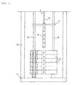
- a conventional weight training machine includes pulleys 12 installed at an upper portion of a support 10 having a base 11 and a wire 13 connected to a holder 14 such that the wire 13 can be wound around the pulleys 12.
- a fixing rod 15 having a plurality of holes extends downward from the holder 14.
- a pair of guides 16 are standing upright at the center area of the support 10 such that the holder 14 can move up and down while being guided by the guides 16.
- a plurality of stacks 17 having insertion holes corresponding to the fixing rod 15 are fitted with the guides 16 such that the stacks 17 can move up and down.
- a hole is formed at one side of each stack 17 corresponding to the holes of the fixing rod 15.
- the fixing rod 15 installed under the holder 14 is vertically inserted into the insertion holes formed at the center of the stacks 17 and a user sets the weight of the stacks 19 by coupling one of the stacks 17 with the fixing rod 15.
- Applicant of the present invention has filed Korean Patent Registration No. 10-0425814 entitled "weight control apparatus for a weight training machine”.
- FIG. 3 shows the weight control apparatus of the weight training machine.
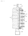
- a pair of guides 420 are mounted on the upper part of a base 410 to which a support (not shown) is mounted and a plate 210 is mounted to the guides 420 such that the plate 210 can slidably move up and down.
- a fixing device 100 having a plurality of fixing pins 130 is mounted in the downward direction at one end of the plate 210.
- a plurality of stacks 310 are mounted to the guides 420 installed on the base 410.
- Each of the stacks 310 is formed in the shape of a brick with a depressed side.
- Each of the stacks 310 is provided at either end thereof with a bearing (not shown).
- an insertion hole 311 is formed and the fixing pin 130 of the fixing device 100 is inserted into the insertion hole 311, which will be described below.
- the fixing device 100 mounted to the one end of the plate 210 is placed at the depressed part of the stack 310.
- the fixing device 100 includes a body 110 having a hollow rectangular shape.
- a locking member 120 provided lengthwise thereof with a plurality of hooks 121 is installed in the body 110.
- the locking member 120 is provided at the upper portion or the lower portion thereof with a spring 122 so that the locking member 120 is moved up and down due to elasticity of the spring 122 and engaged with the fixing pin 130, which will be described below.
- a plurality of fixing pins 130 are inserted into the body 110 of the fixing device 100 from the front portion to the rear portion of the body 110 of the fixing device 100.
- a push button 140 is provided at one end of the fixing pin 140 and a spring 150 is installed between the push button 140 and an outer surface of the body 110 of the fixing device 100 to support the fixing pin 130.
- Guide protrusions are provided lengthwise along the fixing pin 130 and a locking protrusion 131 is provided in the fixing pin 130 to allow the fixing pin 130 to engage with the hook 121 of the locking member 120.
- a stopper is provided at the end of the guide protrusion.
- the fixing pin having the cylindrical structure is inserted into the circular hole of the stack, so that the stack is shaken to the left or right when the stack is moved up and down.
- the thickness of the body of the fixing device is too thick, so the body may protrude in the front direction beyond the stack.
- the volume of the apparatus maybe increased, the external appearance of the apparatus may be deteriorated, and the manufacturing cost may be increased.
- the present invention is the improvement of the Korean Patent Registration No. 10-0425814 and an object of the present invention is to provide a weight control apparatus of a weight training machine, in which a fixing pin inserted into the stack has a plate shape so that the stacks are not shaken to the left or right, a locking member is improved to precisely perform the locking and release operation between a locking protrusion of the fixing pin and the locking member, the locking member is prevented from being deformed or subject to friction to improve the convenience and durability, another button is not operated when one button has been operated to ensure the safety, and the volume of the apparatus is reduced so that the apparatus has the compact structure.
- the weight control apparatus includes a plurality of stacks which are fitted to a pair of guides standing upright between supports on a base such that the stacks slidably move up and down, and which have rectangular locking holes; a body arranged on a front surface of the base, in which the body has a plurality of insertion holes corresponding to the locking holes of the stacks and is provided at an upper portion thereof with a holder; and a cover arranged on the front surface of the body and having a plurality of locking pin members inserted into the insertion holes.
- Each locking pin member includes a rectangular stopper having a recess inwardly recessed, protrusions protruding from both sides of the recess, and locking protrusions protruding from both sides of the stopper; a shaft pin connected to a front end of the stopper; a button arranged on a front end of the shaft pin; and a conical coil spring arranged between the button and the shaft pin.
- the stack is not shaken to the left or right when the stack is moved up and down so the user can take exercise smoothly.
- the locking and releasing operation of the stopper can be precisely performed. Further, the user can smoothlypush the button and abrasion of the locking member can be minimized.
- the volume of the apparatus can be reduced, the aesthetic appearance of the apparatus can be improved and the manufacturing cost of the apparatus can be reduced.
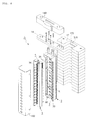
- FIG. 4 is an explodedperspective view showing a weight control apparatus of a weight training machine according to the present invention.
- the weight control apparatus A of the weight training machine includes a base 11, supports 10 installed on the base 11, a pair of guides 16 vertically disposed between the supports 10, a plurality of stacks having rectangular fixing holes 170 and installed to the guides 16 to slidably move up and down, a body 2 installed at a front surface of the base, formed with a plurality of insertion holes 20 corresponding to the fixing holes 170 of the stacks 17 and provided at an upper portion thereof with a holder 14, and a cover 4 installed at a front surface of the body 2 and provided with a plurality of fixing pin members 5 inserted into the insertion holes 20.
- the stacks 17 are weights having the rectangular brick shape and a recess 172 is formed at the center of each stack 17.
- the fixing hole 170 is formed in the recess 172.
- the fixing hole 170 has a rectangular shape identical to the shape of the fixing fin member 5.
- the holder 14 is provided at the upper portion of the body 2 and a holder case 142 is provided at an outer portion of the holder 14.
- the body 2 is installed in the recess 172 of the stacks 17 and moves up and down together with the stacks 17 when a user pushes a button 54.
- the insertion holes 20 are provided lengthwise along the body 2 in correspondence with the fixing holes 170 of the stacks 17.
- the insertion holes 20 have the rectangular shape identical to the shape of the fixing holes 170.
- a plurality of rolling grooves 23 are formed at both sides of the insertion holes 20 of the body 2.
- Rolling units 36 are installed in the rolling grooves 23 in such a manner that the rolling units 36 can make contact with a plate member 32 of the locking member 3 and a plate member 60 of the safety guide 6.
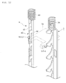
- FIG. 5 is a perspective view showing the fixing pin member of FIG. 4 .
- the fixing pin member 5 includes a rectangular stopper 51 provided at both upper side ends thereof with locking protrusions 515-1 and 515-2 opposite to each other, a shaft pin 52 connected to the upper end of the stopper 51, a button 54 installed at an upper end of the shaft pin 52, and a conical coil spring 53 installed between the button 54 and the shaft pin 52.
- the stopper 51 is made from a metal and inserted into the insertion hole 20 of the body 2 and the fixing hole 170 of the stack 17 to allow the user to set the weight of the stacks 17.
- a recess 512 is formed at the upper end of the stopper 51, so that protrusions 514 are formed at both upper side ends of the stopper 51.
- One end of the shaft pin 52 is screw-coupled into the bottom of the recess 512 and the locking protrusions 515-1 and 515-2 are provided at both upper side ends of the stopper 51.
- the conical coil spring 53 has a diameter which is gradually reduced from a bottom to a top thereof.
- the conical coil spring 53 is flattened in a spiral shape, so that the volume of the conical coil spring 53 can be minimized.
- the length of the shaft pin 52 can be shortened, so that the volume of the weight control apparatus according to the present invention can be reduced.
- FIG. 6 is a perspective view showing the locking member and the safety guide of FIG. 4 .
- the locking member 3 and the safety guide 6 are installed in the body 2 such that the locking protrusions 515-1 and 515-2 of the fixing pin member 5 can be coupled with or decoupled from the locking member 3 and the safety guide 6.
- the locking member 3 includes the plate member 32 having a predetermined length and provided at an upper portion thereof with a spring 39 and a locking protrusion 34 having a saw-tooth shape and provided at one side of the plate member 32.
- the plate member 32 is a metal plate vertically installed corresponding to the rolling groove 23 formed at one side of the insertion holes 20 of the body 2.
- the spring 39 is fitted with the upper end portion of the plate member 32 so that the plate member 32 can be elastically coupled with the upper surface of the body 2 and a plurality of elongated holes 322 are formed at the middle part of the plate member 32.
- Alower endof theplatemember 32 protrudes to the outside through a perforation hole (not shown) formed at the lower end of the body 2 and is attached to a reset button 33 (see, FIGS. 4 , 6 , and 7 ).
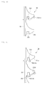
- the locking protrusion 34 includes a protrusion 35 formed at a front lower end thereof with a first inclined surface 351, a recess 352 adjacent to a lower portion of the first inclined surface 351 of the protrusion 35, and an arc-shape groove 354 formed at a lower portion of the recess 352.
- the protrusion 35 When viewed in a side view, the protrusion 35 has a trapezoidal shape and the first inclined surface 351 is inclined downward. In particular, a region between the first inclined surface 351 and the recess 352 is horizontally incised, so that an incised surface 357 is formed.
- the recess 352 is recessed at the end of the incised surface 357 and the locking protrusion 515-1 of the stopper 51 is inserted into the recess 352.
- the arc-shape groove 354 is formed next to the recess 352 at the lower portion of the recess 352. Preferably, a start point of the arc-shape groove 354 is in line with the incised surface 357.
- the safety guide 6 will be further described later in detail.
- FIG. 7 is a longitudinal sectional view showing a coupling state between the fixing plate member and the body.
- a shaft pin member 37 is inserted into the elongated hole 322 formed in the plate member 32 so that the plate member 32 can move up and down.
- the shaft pin member 37 includes a bushing 372 inserted into the elongated hole 322 and a bolt 374 screw-coupled into a screw hole 376 of the body 2 by passing through the bushing 372.
- the rolling unit 36 is installed between the plate member 32 of the locking member 3 and the inner surface of the body 2.
- the rolling unit 36 includes a cylindrical roller, such as a needle bearing.
- the rolling unit 36 is inserted into the rolling groove 23 formed in the body 23 to facilitate the movement of the plate member 32.
- the rolling groove 23 has a width sufficient to receive two rolling units 36 therein.
- a margin space 230 is formed in the rolling groove 23 when the two rolling units 36 are accommodated in the rolling groove 23.
- the rolling units 36 may roll in the rolling groove 23 due to the margin space 230 so that the plate member 32 can smoothly move up and down.
- the reset button 33 is attached to the lower end of the locking member 3, which protrudes out of the body 2.
- the reset button 33 Upon emergency or A/S, the reset button 33 resets the weight control apparatus by releasing the locking state of the fixing pin member 5. If the user pushes up the reset button 33 by using a finger, the locking member 3 is pushed upward, so that all stoppers 51 are released, thereby initializing the weight control apparatus.
- the locking protrusion 515-1 of the stopper 51 is separated from the recess 352 due to the elasticity of the conical coil spring 53 and the stopper 51 is released from the fixing hole 170 of the stack 17 so that the button 54 returns to its initial position.
- the safety guide 6 is installed in the body 2 in opposition to the locking member 3.
- the safety guide 6 includes a plate member 60 having a predetermined length and provided at an upper end thereof with a safety spring 69, a plurality of locking protrusions 62 and apluralityof recesses 63.
- the locking protrusions 62 and the recesses 63 are alternately formed with the regular interval at one side of the plate member 60.
- the locking protrusions 62 have vertical surfaces 622 and the recesses 63 are formed below the vertical surfaces 622.
- the locking protrusions 62 have substantially reverse-L shapes.
- the plate member 60 is a metal plate vertically installed corresponding to the rolling groove 23 formed at one side of the insertion holes 20 of the body 2.
- the safety spring 69 is fitted with the upper end of the plate member 60 to allow the plate member 60 to be elastically coupled with the upper surface of the body and a plurality of elongated holes 604 having a predetermined length are formed at the middle of the plate member 60.
- the lower end of the plate member 60 protrudes to the outside through a perforation hole (not shown) formed at the lower end of the body 2 and a locking button 61 (see, FIG. 4 ) is attached to the lower end of the plate member 60.
- the shaft pin member 37 is inserted into the elongated hole 604 of the safety guide 6 to guide the up-down movement of the plate member 60.
- FIG. 8 is a transverse sectional view showing a coupling state between the locking member and the body.
- the cover 4 covers the front surface of the body 2.
- the cover 4 is installed at the front surface of the body 2 and provided with a plurality of fixing pin members 5 inserted into the insertion holes 20.
- a front surface of the cover 4 is depressed inward so that a recess 42 is formed lengthwise along the cover 4.
- a plurality of holes are formed in the recess 42 and the shaft pins 52 of the fixing pin members 5 are inserted into the holes.
- the recess 42 has a shape corresponding to the shape of the recess 512 of the stopper 51.
- Anti-vibration pads 44 are installed at both sides of the recess 42 to make contact with the locking protrusion 514 of the stopper 51.
- the anti-vibration pads 44 are made from a silicon material.
- a lid 100 is mounted on the cover 4.
- a pair of guides 16 are vertically installed between the supports 10 mounted on the base 11, and a plurality of stacks 17 are fitted with the guides 16.
- the body 2 is accommodated in the recess 172 of the body 2 of the stack 17 and the cover 4 is mounted on the front surface of the body 2.
- a plurality of fixing pin members 5 are installed lengthwise along the cover 4.
- the stoppers 51 are inserted into the insertion holes 20 of the body 2.
- the body 2 lies down on the ground or a working table (not shown) is disposed at the rear surface of the body 2 such that the stoppers 51 are prevented from being separated from the body 2.
- the cover 4 is coupled with the front surface of the body 2 so that the recess 42 of the cover 4 is accommodated in the recess 512 of the stopper 51.
- the conical coil spring 53 is fitted with the shaft pin 52 provided at the front end thereof with the button 54, and the rear end of the shaft pin 52 is inserted into the hole of the cover 4 to screw couple the rear end of the shaft pin 52 with the stopper 51.
- the lower end portion of the conical coil spring 53 having a large diameter is supported by the cover 4 and the upper end portion of the conical coil spring 53 having a small diameter is supported by the button 54. Therefore, the stopper 51 is biased outward due to the elastic force of the conical coil spring 53, so that all buttons 54 of the fixing pin members 5 may protrude.
- the locking member 3 is longitudinally installed at one side of the insertion holes 20 such that the locking protrusions 515-1 and 515-2 provided at both sides of the stopper 51 of the fixing pin member 5 are coupled with the locking member 3 and the safety guide 6 is longitudinally installed at the other side of the insertion holes 20.
- FIG. 9 is a sectional view showing a locking state between the locking member and the fixing pin member in the weight control apparatus of the weight training machine according to the present invention.
- the stopper 51 moves forward so that the stopper 51 is inserted into the fixing hole 170 of the stack 17 by passing through the insertion hole 20 of the body 2.
- FIG. 10 is a view showing an operational state of the fixing pin member in the weight control apparatus of the weight training machine according to the present invention.
- the locking protrusion 515-1 of the fixing pin member 5 moves down along the first inclined surface 351 of the locking protrusion 34 so that the plate member 32 is pushed upward.
- the stacks 17 set by the user are moved up together with the body 2, so that the user can take exercise.
- FIG. 11 is a view showing an operational state of the fixing pin member when the user changes the setting of stacks in the weight control apparatus of the weight training machine according to the present invention.
- the stopper 51 moves forward so that the stopper 51 is inserted into the fixing hole 170 of the stack 17 by passing through the insertion hole 20 of the body 2.
- the locking protrusion 515-1b of another fixing pin member 5 moves down along the inclined surface 3 51b of the locking protrusion 34 while pushing up the plate member 32 and further moves along the second inclined surface 353.
- the lockingprotrusion 515-1b of the stopper 51 is more deeply inserted, so that the locking protrusion 34 is further moved up and down. Therefore, the locking protrusion 515-1a of the stopper 51 is separated from the recess 352.
- the previous stopper 51 moves back due to the elastic force of the conical coil spring 53 installed on the previous stopper 51, so that the locking state is released.
- FIGS. 12 to 14 are views showing a locking state between the safety guide and the fixing pin member in the weight control apparatus of the weight training machine according to the present invention.
- the function of the safety guide 6 may be easily understood with reference to FIGS. 12 to 14 .
- the locking button 61 provided at the lower end of the safety guide 6 makes contact with the base 11, so that the safety guide 6 has been moved up. Therefore, the safety spring 69 provided at the upper portion of the safety guide 6 is compressed.
- the locking button 61 of the safety guide 6 is spaced apart from the base 11, so that the safety spring 69 is expanded due to the elasticity.
- the safety guide 6 moves down so that the lockingprotrusion 515-2 of the stopper 51 is inserted into the recess 64.
- the locking protrusion 515-2b of the stopper 51b which corresponds to the button 54 that is not pressed, makes contact with the vertical surface 622 of the locking protrusion 62 of the safety guide 6, so the stopper 51b may not be operated even if other buttons are pressed.
- buttons are unnecessarily pressed when the user takes exercise, other stoppers may not be operated, so that the user may safety take exercise.
- the locking button 61 of the safety guide 6 makes contact with the base 11, so that the safety guide 6 moves up and the safety spring 69 provided at the upper portion of the safety guide 6 is compressed.
- the locking protrusion 515-2 of the stopper 51 is separated from the recess 54.
Landscapes
- Health & Medical Sciences (AREA)
- Life Sciences & Earth Sciences (AREA)
- Biophysics (AREA)
- Orthopedic Medicine & Surgery (AREA)
- General Health & Medical Sciences (AREA)
- Physical Education & Sports Medicine (AREA)
- Rehabilitation Tools (AREA)
- Portable Nailing Machines And Staplers (AREA)
- Braking Arrangements (AREA)
- Percussion Or Vibration Massage (AREA)
- Instructional Devices (AREA)
- Toys (AREA)
Applications Claiming Priority (2)
| Application Number | Priority Date | Filing Date | Title |
|---|---|---|---|
| KR1020080104022A KR101078332B1 (ko) | 2008-10-23 | 2008-10-23 | 웨이트트레이닝 기구의 중량조절장치 |
| PCT/KR2009/006147 WO2010047554A2 (fr) | 2008-10-23 | 2009-10-23 | Appareil de regulation du poids pour machine d'entraînement au poids |
Publications (3)
| Publication Number | Publication Date |
|---|---|
| EP2351602A2 true EP2351602A2 (fr) | 2011-08-03 |
| EP2351602A4 EP2351602A4 (fr) | 2014-03-12 |
| EP2351602B1 EP2351602B1 (fr) | 2017-07-12 |
Family
ID=42119853
Family Applications (1)
| Application Number | Title | Priority Date | Filing Date |
|---|---|---|---|
| EP09822230.0A Not-in-force EP2351602B1 (fr) | 2008-10-23 | 2009-10-23 | Appareil de regulation du poids pour machine d'entraînement au poids |
Country Status (7)
| Country | Link |
|---|---|
| US (1) | US8632442B2 (fr) |
| EP (1) | EP2351602B1 (fr) |
| KR (1) | KR101078332B1 (fr) |
| CN (1) | CN102202743B (fr) |
| AU (1) | AU2009307206B2 (fr) |
| ES (1) | ES2638500T3 (fr) |
| WO (1) | WO2010047554A2 (fr) |
Families Citing this family (9)
| Publication number | Priority date | Publication date | Assignee | Title |
|---|---|---|---|---|
| KR101078332B1 (ko) * | 2008-10-23 | 2011-11-01 | 이병돈 | 웨이트트레이닝 기구의 중량조절장치 |
| US9079068B2 (en) | 2012-02-21 | 2015-07-14 | Whiterock Exercise, Inc. | Linear bearings and alignment method for weight lifting apparatus |
| US9486662B2 (en) | 2013-01-28 | 2016-11-08 | IncludeFitness, Inc. | Handle with retractable plunger |
| WO2017007054A1 (fr) * | 2015-07-06 | 2017-01-12 | 한태희 | Machine d'entraînement aux poids |
| TWI707709B (zh) * | 2019-12-12 | 2020-10-21 | 清河國際股份有限公司 | 重量訓練設備的重量片間隙調整模組 |
| CN112569538B (zh) * | 2020-12-08 | 2021-10-15 | 上海市浦东医院(复旦大学附属浦东医院) | 一种康复训练用胳膊恢复器 |
| US11911683B2 (en) * | 2021-01-18 | 2024-02-27 | Albert Sorin | Block plate apparatus system and methods of using same |
| KR102675842B1 (ko) * | 2023-09-27 | 2024-06-14 | 정영성 | 장애인용 운동기구 |
| KR102821323B1 (ko) * | 2024-10-08 | 2025-06-16 | (주)카이로스 | 각도 조절 및 잠금이 동시에 이루어질 수 있는 핸들장치 및 이를 포함하는 웨이트 운동기구 |
Family Cites Families (18)
| Publication number | Priority date | Publication date | Assignee | Title |
|---|---|---|---|---|
| US4974838A (en) * | 1989-09-27 | 1990-12-04 | Sollenberger Carl E | Exercise apparatus for performing free weight barbell exercises |
| US5556362A (en) * | 1995-03-20 | 1996-09-17 | Whipps; Allen M. | Automatic weight stack pin selector |
| US6582345B2 (en) * | 2000-02-03 | 2003-06-24 | Normand Roy | Weight holder device for weight lifting apparatus |
| KR100497316B1 (ko) | 2002-11-12 | 2005-06-28 | 이병돈 | 웨이트트레이닝 기구의 스택 고정판의 안전 및 풀림방지장치 |
| KR100425814B1 (ko) | 2002-01-28 | 2004-04-13 | 이병돈 | 웨이트트레이닝 기구의 중량조절장치 |
| KR100497315B1 (ko) | 2002-11-12 | 2005-06-28 | 이병돈 | 웨이트트레이닝 기구의 중량조절장치 |
| EP1469916A1 (fr) * | 2002-01-28 | 2004-10-27 | Lee, Byung-don | Dispositif de commande du poids pour une machine d'entrainement aux poids et procede correspondant |
| KR20040041847A (ko) | 2002-11-12 | 2004-05-20 | 이병돈 | 웨이트트레이닝 기구의 중량조절장치 및 중량조절 방법 |
| TWI259099B (en) * | 2003-11-06 | 2006-08-01 | Tanren Co Ltd | Training machine |
| US7252627B2 (en) * | 2004-02-10 | 2007-08-07 | Tuffstuff Fitness Equipment, Inc. | Therapy weight system |
| US7507191B2 (en) * | 2004-02-25 | 2009-03-24 | Kyriacos Mark Zachary | Dual rotation rotary torso exercise bench |
| KR100685669B1 (ko) * | 2004-11-26 | 2007-02-23 | 이병돈 | 웨이트트레이닝 기구용 스택 |
| US7537550B1 (en) * | 2004-12-14 | 2009-05-26 | Krull Mark A | Exercise weight stack methods and apparatus |
| US7758478B2 (en) * | 2005-03-17 | 2010-07-20 | Nautilus, Inc. | Weight selection apparatus for a weight stack |
| US20060211549A1 (en) * | 2005-03-18 | 2006-09-21 | Nohejl Russell J | Abdominal exercise and training apparatus |
| KR100549407B1 (ko) | 2005-05-26 | 2006-02-08 | 김여주 | 웨이트 운동기구 핀장치 및 웨이트 운동기구 |
| KR101020305B1 (ko) | 2008-06-03 | 2011-03-08 | 한상현 | 웨이트 머신 운동기의 중량설정 모니터링 시스템 |
| KR101078332B1 (ko) * | 2008-10-23 | 2011-11-01 | 이병돈 | 웨이트트레이닝 기구의 중량조절장치 |
-
2008
- 2008-10-23 KR KR1020080104022A patent/KR101078332B1/ko not_active Ceased
-
2009
- 2009-10-23 WO PCT/KR2009/006147 patent/WO2010047554A2/fr not_active Ceased
- 2009-10-23 AU AU2009307206A patent/AU2009307206B2/en not_active Ceased
- 2009-10-23 US US13/123,631 patent/US8632442B2/en not_active Expired - Fee Related
- 2009-10-23 ES ES09822230.0T patent/ES2638500T3/es active Active
- 2009-10-23 CN CN2009801420036A patent/CN102202743B/zh not_active Expired - Fee Related
- 2009-10-23 EP EP09822230.0A patent/EP2351602B1/fr not_active Not-in-force
Also Published As
| Publication number | Publication date |
|---|---|
| CN102202743A (zh) | 2011-09-28 |
| EP2351602B1 (fr) | 2017-07-12 |
| US8632442B2 (en) | 2014-01-21 |
| AU2009307206A1 (en) | 2010-04-29 |
| CN102202743B (zh) | 2013-11-20 |
| ES2638500T3 (es) | 2017-10-23 |
| WO2010047554A3 (fr) | 2010-08-05 |
| US20110195823A1 (en) | 2011-08-11 |
| AU2009307206B2 (en) | 2012-05-31 |
| KR20100045008A (ko) | 2010-05-03 |
| WO2010047554A2 (fr) | 2010-04-29 |
| KR101078332B1 (ko) | 2011-11-01 |
| EP2351602A4 (fr) | 2014-03-12 |
Similar Documents
| Publication | Publication Date | Title |
|---|---|---|
| EP2351602B1 (fr) | Appareil de regulation du poids pour machine d'entraînement au poids | |
| EP2111777A1 (fr) | Dispositif de couplage pour structure de cadre de berceau de bébé | |
| EP3730000B1 (fr) | Dispositif coulissant pour tiroir | |
| US7104203B2 (en) | Height adjustable device for a retractable tube assembly | |
| US5458020A (en) | Pull rod structure of a baggage cart | |
| US9407737B2 (en) | Communication terminal | |
| JP2017087762A (ja) | 車両用シートスライド装置 | |
| JP2009297177A (ja) | 折り畳み椅子を有する鞄 | |
| KR102246019B1 (ko) | 가구의 높이조절장치 | |
| JP4451257B2 (ja) | 椅子型便器の肘掛け昇降機構 | |
| WO2001097672A1 (fr) | Dispositif de reglage de longueur de tube de prolongement d'aspiration pour aspirateur | |
| EP2233117B1 (fr) | Mécanisme d'ajustement d'accoudoir de fauteuil roulant | |
| GB2584582A (en) | Baby carriage and backrest angle adjusting device thereof | |
| CN109826512B (zh) | 挂锁 | |
| JP2008290563A (ja) | シートトラック | |
| CN222615001U (zh) | 一种便于操作的后把手锁定结构 | |
| JP2022092845A (ja) | 移動机 | |
| KR101014538B1 (ko) | 헤드레스트 폴딩장치 | |
| JP3129667U (ja) | キャリーハンドル装置 | |
| JP5518691B2 (ja) | ショルダアンカ装置 | |
| JP2020120965A (ja) | キャリーバッグ | |
| JP3961303B2 (ja) | スイッチ装置 | |
| EP1438906B1 (fr) | Coulant pour parapluie avec dispositif de verrouillage | |
| JP4351076B2 (ja) | シートスライド装置 | |
| JPS6331650Y2 (fr) |
Legal Events
| Date | Code | Title | Description |
|---|---|---|---|
| PUAI | Public reference made under article 153(3) epc to a published international application that has entered the european phase |
Free format text: ORIGINAL CODE: 0009012 |
|
| 17P | Request for examination filed |
Effective date: 20110520 |
|
| AK | Designated contracting states |
Kind code of ref document: A2 Designated state(s): AT BE BG CH CY CZ DE DK EE ES FI FR GB GR HR HU IE IS IT LI LT LU LV MC MK MT NL NO PL PT RO SE SI SK SM TR |
|
| DAX | Request for extension of the european patent (deleted) | ||
| A4 | Supplementary search report drawn up and despatched |
Effective date: 20140206 |
|
| RIC1 | Information provided on ipc code assigned before grant |
Ipc: A63B 21/062 20060101AFI20140131BHEP |
|
| 17Q | First examination report despatched |
Effective date: 20160606 |
|
| GRAP | Despatch of communication of intention to grant a patent |
Free format text: ORIGINAL CODE: EPIDOSNIGR1 |
|
| STAA | Information on the status of an ep patent application or granted ep patent |
Free format text: STATUS: GRANT OF PATENT IS INTENDED |
|
| INTG | Intention to grant announced |
Effective date: 20170207 |
|
| GRAS | Grant fee paid |
Free format text: ORIGINAL CODE: EPIDOSNIGR3 |
|
| GRAA | (expected) grant |
Free format text: ORIGINAL CODE: 0009210 |
|
| STAA | Information on the status of an ep patent application or granted ep patent |
Free format text: STATUS: THE PATENT HAS BEEN GRANTED |
|
| AK | Designated contracting states |
Kind code of ref document: B1 Designated state(s): AT BE BG CH CY CZ DE DK EE ES FI FR GB GR HR HU IE IS IT LI LT LU LV MC MK MT NL NO PL PT RO SE SI SK SM TR |
|
| REG | Reference to a national code |
Ref country code: GB Ref legal event code: FG4D |
|
| REG | Reference to a national code |
Ref country code: CH Ref legal event code: EP |
|
| REG | Reference to a national code |
Ref country code: AT Ref legal event code: REF Ref document number: 907801 Country of ref document: AT Kind code of ref document: T Effective date: 20170715 |
|
| REG | Reference to a national code |
Ref country code: IE Ref legal event code: FG4D |
|
| REG | Reference to a national code |
Ref country code: DE Ref legal event code: R096 Ref document number: 602009047138 Country of ref document: DE |
|
| REG | Reference to a national code |
Ref country code: NL Ref legal event code: FP |
|
| REG | Reference to a national code |
Ref country code: ES Ref legal event code: FG2A Ref document number: 2638500 Country of ref document: ES Kind code of ref document: T3 Effective date: 20171023 |
|
| REG | Reference to a national code |
Ref country code: FR Ref legal event code: PLFP Year of fee payment: 9 |
|
| REG | Reference to a national code |
Ref country code: LT Ref legal event code: MG4D |
|
| REG | Reference to a national code |
Ref country code: AT Ref legal event code: MK05 Ref document number: 907801 Country of ref document: AT Kind code of ref document: T Effective date: 20170712 |
|
| PG25 | Lapsed in a contracting state [announced via postgrant information from national office to epo] |
Ref country code: NO Free format text: LAPSE BECAUSE OF FAILURE TO SUBMIT A TRANSLATION OF THE DESCRIPTION OR TO PAY THE FEE WITHIN THE PRESCRIBED TIME-LIMIT Effective date: 20171012 Ref country code: HR Free format text: LAPSE BECAUSE OF FAILURE TO SUBMIT A TRANSLATION OF THE DESCRIPTION OR TO PAY THE FEE WITHIN THE PRESCRIBED TIME-LIMIT Effective date: 20170712 Ref country code: LT Free format text: LAPSE BECAUSE OF FAILURE TO SUBMIT A TRANSLATION OF THE DESCRIPTION OR TO PAY THE FEE WITHIN THE PRESCRIBED TIME-LIMIT Effective date: 20170712 Ref country code: AT Free format text: LAPSE BECAUSE OF FAILURE TO SUBMIT A TRANSLATION OF THE DESCRIPTION OR TO PAY THE FEE WITHIN THE PRESCRIBED TIME-LIMIT Effective date: 20170712 Ref country code: FI Free format text: LAPSE BECAUSE OF FAILURE TO SUBMIT A TRANSLATION OF THE DESCRIPTION OR TO PAY THE FEE WITHIN THE PRESCRIBED TIME-LIMIT Effective date: 20170712 Ref country code: SE Free format text: LAPSE BECAUSE OF FAILURE TO SUBMIT A TRANSLATION OF THE DESCRIPTION OR TO PAY THE FEE WITHIN THE PRESCRIBED TIME-LIMIT Effective date: 20170712 |
|
| PG25 | Lapsed in a contracting state [announced via postgrant information from national office to epo] |
Ref country code: IS Free format text: LAPSE BECAUSE OF FAILURE TO SUBMIT A TRANSLATION OF THE DESCRIPTION OR TO PAY THE FEE WITHIN THE PRESCRIBED TIME-LIMIT Effective date: 20171112 Ref country code: LV Free format text: LAPSE BECAUSE OF FAILURE TO SUBMIT A TRANSLATION OF THE DESCRIPTION OR TO PAY THE FEE WITHIN THE PRESCRIBED TIME-LIMIT Effective date: 20170712 Ref country code: BG Free format text: LAPSE BECAUSE OF FAILURE TO SUBMIT A TRANSLATION OF THE DESCRIPTION OR TO PAY THE FEE WITHIN THE PRESCRIBED TIME-LIMIT Effective date: 20171012 Ref country code: PL Free format text: LAPSE BECAUSE OF FAILURE TO SUBMIT A TRANSLATION OF THE DESCRIPTION OR TO PAY THE FEE WITHIN THE PRESCRIBED TIME-LIMIT Effective date: 20170712 Ref country code: GR Free format text: LAPSE BECAUSE OF FAILURE TO SUBMIT A TRANSLATION OF THE DESCRIPTION OR TO PAY THE FEE WITHIN THE PRESCRIBED TIME-LIMIT Effective date: 20171013 |
|
| REG | Reference to a national code |
Ref country code: DE Ref legal event code: R097 Ref document number: 602009047138 Country of ref document: DE |
|
| PG25 | Lapsed in a contracting state [announced via postgrant information from national office to epo] |
Ref country code: CZ Free format text: LAPSE BECAUSE OF FAILURE TO SUBMIT A TRANSLATION OF THE DESCRIPTION OR TO PAY THE FEE WITHIN THE PRESCRIBED TIME-LIMIT Effective date: 20170712 Ref country code: RO Free format text: LAPSE BECAUSE OF FAILURE TO SUBMIT A TRANSLATION OF THE DESCRIPTION OR TO PAY THE FEE WITHIN THE PRESCRIBED TIME-LIMIT Effective date: 20170712 Ref country code: DK Free format text: LAPSE BECAUSE OF FAILURE TO SUBMIT A TRANSLATION OF THE DESCRIPTION OR TO PAY THE FEE WITHIN THE PRESCRIBED TIME-LIMIT Effective date: 20170712 |
|
| PLBE | No opposition filed within time limit |
Free format text: ORIGINAL CODE: 0009261 |
|
| STAA | Information on the status of an ep patent application or granted ep patent |
Free format text: STATUS: NO OPPOSITION FILED WITHIN TIME LIMIT |
|
| PG25 | Lapsed in a contracting state [announced via postgrant information from national office to epo] |
Ref country code: SK Free format text: LAPSE BECAUSE OF FAILURE TO SUBMIT A TRANSLATION OF THE DESCRIPTION OR TO PAY THE FEE WITHIN THE PRESCRIBED TIME-LIMIT Effective date: 20170712 Ref country code: EE Free format text: LAPSE BECAUSE OF FAILURE TO SUBMIT A TRANSLATION OF THE DESCRIPTION OR TO PAY THE FEE WITHIN THE PRESCRIBED TIME-LIMIT Effective date: 20170712 Ref country code: SM Free format text: LAPSE BECAUSE OF FAILURE TO SUBMIT A TRANSLATION OF THE DESCRIPTION OR TO PAY THE FEE WITHIN THE PRESCRIBED TIME-LIMIT Effective date: 20170712 Ref country code: MC Free format text: LAPSE BECAUSE OF FAILURE TO SUBMIT A TRANSLATION OF THE DESCRIPTION OR TO PAY THE FEE WITHIN THE PRESCRIBED TIME-LIMIT Effective date: 20170712 |
|
| REG | Reference to a national code |
Ref country code: CH Ref legal event code: PL |
|
| 26N | No opposition filed |
Effective date: 20180413 |
|
| REG | Reference to a national code |
Ref country code: IE Ref legal event code: MM4A |
|
| PG25 | Lapsed in a contracting state [announced via postgrant information from national office to epo] |
Ref country code: LI Free format text: LAPSE BECAUSE OF NON-PAYMENT OF DUE FEES Effective date: 20171031 Ref country code: CH Free format text: LAPSE BECAUSE OF NON-PAYMENT OF DUE FEES Effective date: 20171031 Ref country code: LU Free format text: LAPSE BECAUSE OF NON-PAYMENT OF DUE FEES Effective date: 20171023 |
|
| REG | Reference to a national code |
Ref country code: BE Ref legal event code: MM Effective date: 20171031 |
|
| PG25 | Lapsed in a contracting state [announced via postgrant information from national office to epo] |
Ref country code: BE Free format text: LAPSE BECAUSE OF NON-PAYMENT OF DUE FEES Effective date: 20171031 Ref country code: SI Free format text: LAPSE BECAUSE OF FAILURE TO SUBMIT A TRANSLATION OF THE DESCRIPTION OR TO PAY THE FEE WITHIN THE PRESCRIBED TIME-LIMIT Effective date: 20170712 |
|
| PG25 | Lapsed in a contracting state [announced via postgrant information from national office to epo] |
Ref country code: MT Free format text: LAPSE BECAUSE OF NON-PAYMENT OF DUE FEES Effective date: 20171023 |
|
| REG | Reference to a national code |
Ref country code: FR Ref legal event code: PLFP Year of fee payment: 10 |
|
| PG25 | Lapsed in a contracting state [announced via postgrant information from national office to epo] |
Ref country code: IE Free format text: LAPSE BECAUSE OF NON-PAYMENT OF DUE FEES Effective date: 20171023 |
|
| PGFP | Annual fee paid to national office [announced via postgrant information from national office to epo] |
Ref country code: NL Payment date: 20181019 Year of fee payment: 10 |
|
| PG25 | Lapsed in a contracting state [announced via postgrant information from national office to epo] |
Ref country code: HU Free format text: LAPSE BECAUSE OF FAILURE TO SUBMIT A TRANSLATION OF THE DESCRIPTION OR TO PAY THE FEE WITHIN THE PRESCRIBED TIME-LIMIT; INVALID AB INITIO Effective date: 20091023 |
|
| PG25 | Lapsed in a contracting state [announced via postgrant information from national office to epo] |
Ref country code: CY Free format text: LAPSE BECAUSE OF NON-PAYMENT OF DUE FEES Effective date: 20170712 |
|
| PG25 | Lapsed in a contracting state [announced via postgrant information from national office to epo] |
Ref country code: MK Free format text: LAPSE BECAUSE OF FAILURE TO SUBMIT A TRANSLATION OF THE DESCRIPTION OR TO PAY THE FEE WITHIN THE PRESCRIBED TIME-LIMIT Effective date: 20170712 |
|
| PGFP | Annual fee paid to national office [announced via postgrant information from national office to epo] |
Ref country code: DE Payment date: 20191031 Year of fee payment: 11 |
|
| PGFP | Annual fee paid to national office [announced via postgrant information from national office to epo] |
Ref country code: IT Payment date: 20191028 Year of fee payment: 11 Ref country code: ES Payment date: 20191122 Year of fee payment: 11 Ref country code: FR Payment date: 20191028 Year of fee payment: 11 |
|
| PG25 | Lapsed in a contracting state [announced via postgrant information from national office to epo] |
Ref country code: TR Free format text: LAPSE BECAUSE OF FAILURE TO SUBMIT A TRANSLATION OF THE DESCRIPTION OR TO PAY THE FEE WITHIN THE PRESCRIBED TIME-LIMIT Effective date: 20170712 |
|
| PGFP | Annual fee paid to national office [announced via postgrant information from national office to epo] |
Ref country code: GB Payment date: 20191021 Year of fee payment: 11 |
|
| PG25 | Lapsed in a contracting state [announced via postgrant information from national office to epo] |
Ref country code: PT Free format text: LAPSE BECAUSE OF FAILURE TO SUBMIT A TRANSLATION OF THE DESCRIPTION OR TO PAY THE FEE WITHIN THE PRESCRIBED TIME-LIMIT Effective date: 20170712 |
|
| REG | Reference to a national code |
Ref country code: NL Ref legal event code: MM Effective date: 20191101 |
|
| PG25 | Lapsed in a contracting state [announced via postgrant information from national office to epo] |
Ref country code: NL Free format text: LAPSE BECAUSE OF NON-PAYMENT OF DUE FEES Effective date: 20191101 |
|
| REG | Reference to a national code |
Ref country code: DE Ref legal event code: R119 Ref document number: 602009047138 Country of ref document: DE |
|
| GBPC | Gb: european patent ceased through non-payment of renewal fee |
Effective date: 20201023 |
|
| PG25 | Lapsed in a contracting state [announced via postgrant information from national office to epo] |
Ref country code: DE Free format text: LAPSE BECAUSE OF NON-PAYMENT OF DUE FEES Effective date: 20210501 Ref country code: FR Free format text: LAPSE BECAUSE OF NON-PAYMENT OF DUE FEES Effective date: 20201031 |
|
| PG25 | Lapsed in a contracting state [announced via postgrant information from national office to epo] |
Ref country code: GB Free format text: LAPSE BECAUSE OF NON-PAYMENT OF DUE FEES Effective date: 20201023 |
|
| PG25 | Lapsed in a contracting state [announced via postgrant information from national office to epo] |
Ref country code: IT Free format text: LAPSE BECAUSE OF NON-PAYMENT OF DUE FEES Effective date: 20201023 |
|
| REG | Reference to a national code |
Ref country code: ES Ref legal event code: FD2A Effective date: 20220128 |
|
| PG25 | Lapsed in a contracting state [announced via postgrant information from national office to epo] |
Ref country code: ES Free format text: LAPSE BECAUSE OF NON-PAYMENT OF DUE FEES Effective date: 20201024 |