EP2352003B1 - Methods and systems for evaporative cooling infrared thermographic leak detection - Google Patents
Methods and systems for evaporative cooling infrared thermographic leak detection Download PDFInfo
- Publication number
- EP2352003B1 EP2352003B1 EP11151813.0A EP11151813A EP2352003B1 EP 2352003 B1 EP2352003 B1 EP 2352003B1 EP 11151813 A EP11151813 A EP 11151813A EP 2352003 B1 EP2352003 B1 EP 2352003B1
- Authority
- EP
- European Patent Office
- Prior art keywords
- tank
- humidity
- environment
- air
- pressure
- Prior art date
- Legal status (The legal status is an assumption and is not a legal conclusion. Google has not performed a legal analysis and makes no representation as to the accuracy of the status listed.)
- Active
Links
Images


Classifications
-
- G—PHYSICS
- G01—MEASURING; TESTING
- G01M—TESTING STATIC OR DYNAMIC BALANCE OF MACHINES OR STRUCTURES; TESTING OF STRUCTURES OR APPARATUS, NOT OTHERWISE PROVIDED FOR
- G01M3/00—Investigating fluid-tightness of structures
- G01M3/002—Investigating fluid-tightness of structures by using thermal means
Definitions
- the field of the disclosure relates generally to leak detection on vessels and tanks, and more specifically, to methods and systems for evaporative cooling infrared thermographic leak detection.
- Infrared thermography can be utilized to find leaks in vessels and tanks when the velocity flow through the leakage areas is high enough to impart a temperature change to the surrounding areas.
- the amounts of pressurization are very low.
- any temperature changes around a leakage area, or in the leakage area itself may be masked by sealant, the material from which the tank or vessel is built (e.g., aluminum) and the fasteners immediately adjacent to the leak.
- sealant the material from which the tank or vessel is built (e.g., aluminum) and the fasteners immediately adjacent to the leak.
- infrared thermography on its own is not sufficient to provide a complete solution to leak detection, especially for commercial aircraft fuel tank testing and/or cabin pressurization testing.
- traditional leak detection methods using infrared thermography alone are strongly dependant on high velocities at the leakage areas to impart a localized temperature change for detection and high velocities generally require testing under higher pressures.
- evaporative cooling uses the natural relationship between relative humidity, water and air temperature.
- Relative humidity is defined as the ratio of the actual vapor pressure to the pressure of saturated vapor of air at the prevailing dry bulb temperature. It is thus an indication of the amount of water vapor that can be absorbed by the air until it reaches 100% relative humidity.
- dehumidified air leaving the one area at a reduced water content (de-humidified to a lower relative humidity value) and moving into an area of higher humidity has the capacity to absorb more water than the surrounding atmosphere thereby producing a localized drop in temperature, and hence the term evaporative cooling.
- the method comprises the steps of preparing and applying a water soluble non-staining indicator dye to a test surface, observing color changes indicative of hydrocarbon leaks and removing the indicator dye from the test surface.
- the apparatus comprises in combination an apparatus for preparing the indicator dye, a spray apparatus for applying the indicator dye to the test surface and surface cleaning apparatus for removing the dye from the test surface.
- the indicator dye comprises a major portion of a dry inert mineral carrier and from about 0.1 to about 5.0 weight percent of a direct dye which is non-staining on painted surfaces and which does not migrate into or penetrate polyurethane or epoxy resin base painted surfaces.”
- the embodiments described herein relate to the detection of leaks within pressurized vessels using infrared thermography to detect areas in which evaporated cooling is occurring.
- the described embodiments of the invention provide a method of leak detection on slightly pressurized aircraft fuel tanks (description in relation to vessels and cabins is by way of example only) without the use of hazardous substances or the application of indicators to detect a presence of such substances.
- the embodiments also address the problems associated with the testing of aircraft fuel tanks that are tested under relatively lower pressures, where the velocity flows emanated from leakage areas are so low that temperature changes are too low for stand alone infrared visualization or in situations where the leakages (and associated temperature changes) are masked and/or absorbed) by sealant, o-rings, or other forms of construction material.
- evaporative cooling uses the natural relationship between relative humidity, water and air temperature and relative humidity is the actual vapor pressure to the pressure of saturated vapor of air at the prevailing dry bulb temperature and is an indication of the amount of water vapor that can be absorbed by the air until it reaches 100% relative humidity.
- the air leaving the leakage area at a reduced water content has the capacity to absorb more water than the surrounding atmosphere external to the test piece.
- the leakage areas and external to the article under test
- there exists a mixture zone where low relative humidity air passing through the leak area, with a velocity component, is mixed with stationary air of a higher relative humidity value, which causes evaporation of moisture from the stationary air.
- This localized evaporation of external air imparts a temperature drop proximate the leakage area that can be detected with an infrared camera.
- test piece e.g., a fuel tank, aircraft cabin, or other vessel
- the dependence on a velocity profile at the leakage area is significantly reduced as well as any influence that may be imparted by the material surrounding the leakage area which would otherwise mask actual leaks.
- a humidity differential may be accomplished by adding humidity to a suspected leakage area.
- aircraft manufacturing and service method 100 may include specification and design 102 of aircraft 200 and material procurement 104.
- aircraft 200 During production, component and subassembly manufacturing 106 and system integration 108 of aircraft 200 takes place. Thereafter, aircraft 200 may go through certification and delivery 110 in order to be placed in service 112. While in service by a customer, aircraft 200 is scheduled for routine maintenance and service 114 (which may also include modification, reconfiguration, refurbishment, and so on).
- Each of the processes of aircraft manufacturing and service method 100 may be performed or carried out by a system integrator, a third party, and/or an operator (e.g., a customer).
- a system integrator may include, without limitation, any number of aircraft manufacturers and major-system subcontractors
- a third party may include, for example, without limitation, any number of venders, subcontractors, and suppliers
- an operator may be an airline, leasing company, military entity, service organization, and so on.
- aircraft 200 produced by aircraft manufacturing and service method 100 may include airframe 202 with a plurality of systems 204 and interior 206.
- systems 204 include one or more of propulsion system 208, electrical system 210, hydraulic system 212, and environmental system 214. Any number of other systems may be included in this example.
- propulsion system 208 one or more of propulsion system 208, electrical system 210, hydraulic system 212, and environmental system 214. Any number of other systems may be included in this example.
- electrical system 210 electrical system 210
- hydraulic system 212 hydraulic system
- environmental system 214 any number of other systems may be included in this example.
- Any number of other systems may be included in this example.
- an aerospace example is shown, the principles of the disclosure may be applied to other industries, such as the automotive, medical, food or petrochemical industry.
- Apparatus and methods embodied herein may be employed during any one or more of the stages of aircraft manufacturing and service method 100.
- components or subassemblies corresponding to component and subassembly manufacturing 106 may be fabricated or manufactured in a manner similar to components or subassemblies produced while aircraft 200 is in service.
- one or more apparatus embodiments, method embodiments, or a combination thereof may be utilized during component and subassembly manufacturing 106 and system integration 108, for example, without limitation, by substantially expediting assembly of or reducing the cost of aircraft 200.
- one or more of apparatus embodiments, method embodiments, or a combination thereof may be utilized while aircraft 200 is in service, for example, without limitation, to maintenance and service 114 may be used during system integration 108 and/or maintenance and service 114 to determine whether parts may be connected and/or mated to each other.
- FIG 3 is a side cross-sectional view of a cover plate 300 that is inserted into an opening 302 in one known fuel tank 304.
- a fuel tank is not simply a vessel with an opening for fuel insertion and another for fuel consumption.
- a fuel tank such as fuel tank 304 may include many openings where cover plates are utilized for the mounting of sensors or other components within the fuel tank.
- certain fuel tanks are physically large in size which dictates that they be fabricated from multiple piece parts that are put together, for example through the use of mechanical fasteners and/or welding.
- the cover plates are configured to form a seal between it and the tank under test, seals are known to fail, as are mechanical fasteners.
- a welded area may include one or more voids within the welding zone that negate the sealing effect of welding.
- the opening 302 in the illustrated embodiment is an indented area that is sized for the insertion of the cover plate 300 and defines a sealing area 312 between a surface 314 of the fuel tank 304 and a surface 316 of the cover plate 300.
- a sealer, an O-ring, or a gasket is utilized between surfaces 314 and 316. Leaks may occur with sealer and with gaskets.
- a secondary opening 320 may be included within the fuel tank 304 for the mounting of an instrument 330. Instrument 330 represents any device that may be mounted within an opening on the material that makes up the fuel tank 304.
- FIG. 4 is a diagram of a system 400 for putting dehumidified air into a tank under test 402.
- System 400 includes a dehumidifier 410 that receives air 412, removes moisture from that air, thereby outputting dehumidified air 414 through an output 416 of the dehumidifier 410.
- the ambient air within the tank under test has to be removed over time (e.g., displaced by the lower humidity air).
- the air drawn into the dehumidifier 410 is drawn from the tank 402, resulting in a quasi-closed loop humidity reduction system.
- a pump 420 may be included within system 400 to receive the dehumidified air 414 at an input 422 and pump the air through an output 424 of the pump 420 in order to maintain a desired pressure of dehumidified air within the tank 304.
- pump 420 supplies dehumidified air at a pressure 426 to tank 304.
- a valve 430 may be included that operates to maintain a pressure of the dehumidified air within tank 304 without operation of the pump 420 or the dehumidifier 410.
- tank 304 is illustrated as having a leak 450. As described further in the following paragraphs, the reduced humidity air 452 escaping tank 304 through leak 450 will react with the air surrounding the leak 450 which is at a higher level of humidity.
- thermographic imaging system 460 includes a thermographic (infrared) camera 462, along with and for example, an image processing system 464 and may include one or both of a display 466 and storage 468 for thermographic images.
- thermographic camera 462 when thermographic camera 462 is in the vicinity of leak 450, the camera 462 will be able to sense the temperature drop imparted by evaporative cooling as described herein and image processing system 464 operates to provide data compatible for viewing on display 466 and/or for storage within storage 468.
- Figure 5 is a mock thermographic illustration of the cover plate 300 of Figure 3 attached to tank under test 304 using a plurality of fasteners 310.
- the embodiment illustrated by Figure 5 is an embodiment where thermographic camera 462 does not sense any evaporative cooling occurring in the vicinity of cover plate 300.
- Figure 6 is a mock thermographic illustration of the cover plate 300 and tank 304 which includes a leak 450 (also shown in Figure 4 ) which allows lower humidity air within the tank 304 to pass through leak 450 and mix with air of an increased humidity outside of the tank 304.
- the result, as described herein, is an area 600 of decreased temperature that has been sensed by thermographic camera 462.
- Area 600 may include several subareas within. For example, at an area closest to leak 450, an image 602 of a lower temperature area 602 may be surrounded by an image of an area 604 having a temperature between that of area 602 and that of the area surrounding area 604.
- testing has been performed at various pressure differentials.
- a pressure differential between the exterior and interior of 6 psig higher pressure in interior of tank being tested
- the temperature differential was also 0.6 degree C with a tank internal pressure of 4 psig.
- the temperature differential was 0.5 degree C with a tank internal pressure of 2 psig, 0.5 psig, and 0.25 psig.
- a temperature differential was able to be discerned with a tank internal pressure of less than 0.25 psig as compared to the environment external to the tank under test.
- the temperature of the tank leakage area (prior to the initiation of leak testing) was about 19.5 degrees C, and as described above, once the leakage initiated evaporative cooling, the temperature in the leakage area was consistently reduced below 19 degrees C.
- the evaporative cooling process described herein provides a capability to visualize leaks in tanks, vessels, and cabins down to less than a 0.25 psi pressure differential as well as the capability to identify leakage areas down to 20 microns in size.
- thermographic leak detection relies on a temperature change at the leakage areas. This temperature change is brought about as a result of a velocity increase of the pressurized air passing through the leakage areas.
- Previous research has shown that in many cases the pressure differential across the vessel under test, results in a very low velocity change in the air passing through such a leak, resulting in a temperature difference that is below the typical infrared detector threshold of 0.1 degrees C.
- introduction of evaporative cooling to such a process, as described herein allows for the sensing of temperature changes that occur, even at such a low velocity.
- processes incorporating the described embodiments provide the ability to visualize leakage areas with a greater accuracy over tank testing processes than using helium and helium detectors.
- Helium and helium detectors only provide an approximation as to where leaks are located in a tank or other vessel.
- the introduction of a humidity differential as described herein tends to reduce buildup of trapped moisture pockets within the vessel being tested. While described herein as using air with lower and higher humidity, embodiments which utilize gases other than air may be utilized, for example, nitrogen or other gases that can be humidified and dehumidified.
- Evaporative cooling combined with infrared thermographic imaging does not use any hazardous substances or chemicals and has no ongoing material running costs as compared to anhydrous ammonia/indicator or helium/helium detector methods. Evaporative cooling combined with infrared thermographic imaging produces superior results in the time it takes to use the helium/helium detector method and can provide leak testing/indication in less time that it takes to carry out an anhydrous ammonia/indicator leak test.
- Evaporative cooling combined with infrared thermographic imaging eliminates the ongoing use of hazardous chemicals, and thus eliminates most of the environmental impact that is found in other testing methodologies.
- detection is possible through the identification of 'made to measure' or modified air dehumidifiers upstream of the test article and the presence of infrared cameras.
Landscapes
- Physics & Mathematics (AREA)
- General Physics & Mathematics (AREA)
- Examining Or Testing Airtightness (AREA)
Description
- The field of the disclosure relates generally to leak detection on vessels and tanks, and more specifically, to methods and systems for evaporative cooling infrared thermographic leak detection.
- Infrared thermography can be utilized to find leaks in vessels and tanks when the velocity flow through the leakage areas is high enough to impart a temperature change to the surrounding areas. However, in commercial aircraft fuel tank testing, the amounts of pressurization are very low. In these low pressure testing situations, any temperature changes around a leakage area, or in the leakage area itself, may be masked by sealant, the material from which the tank or vessel is built (e.g., aluminum) and the fasteners immediately adjacent to the leak. As a result, in these low velocity areas, infrared thermography on its own is not sufficient to provide a complete solution to leak detection, especially for commercial aircraft fuel tank testing and/or cabin pressurization testing. As a result, traditional leak detection methods using infrared thermography alone are strongly dependant on high velocities at the leakage areas to impart a localized temperature change for detection and high velocities generally require testing under higher pressures.
- It is desirable to accomplish leak testing at lower pressures. Therefore, in one current tank testing method, all external seams of the tank are painted with an indicator paint that reacts when in contact with anhydrous ammonia. A fifteen percent anhydrous ammonia/air mixture is then used to pressurize the tanks and any leaks are shown through discoloration of the indicator paint. Leakage areas are then noted and the indicator paint is removed and a repair or refurbishment of the tank is undertaken. In another currently used tank testing method, a five percent helium gas/air mixture is used along with helium detectors to determine the presence of any leakage area associated with the pressurized tank.
- One downside to the above described testing methods is the recurring material costs associated with Anhydrous ammonia, helium and the indicators. In the case of anhydrous ammonia, it is also a hazardous substance. The application and removal of the indicator associated with the anhydrous ammonia testing method is an added labor cost as well. Helium is an asphyxiant and side effects are proportional to oxygen displacement. Further, helium detectors do not have the ability to show visualization of leaks but provide only an approximation of where the leaks are.
- In contrast to the above leak testing methodologies, evaporative cooling uses the natural relationship between relative humidity, water and air temperature. Relative humidity is defined as the ratio of the actual vapor pressure to the pressure of saturated vapor of air at the prevailing dry bulb temperature. It is thus an indication of the amount of water vapor that can be absorbed by the air until it reaches 100% relative humidity. In the context of evaporative cooling, dehumidified air leaving the one area at a reduced water content (de-humidified to a lower relative humidity value) and moving into an area of higher humidity has the capacity to absorb more water than the surrounding atmosphere thereby producing a localized drop in temperature, and hence the term evaporative cooling.
-
DE 10 2008 010619 in the abstract states "A method involving loading a surface of an evacuation system to be tested, with a fluid, and measuring a surface temperature. Evaporative loss of the fluid is detected, where the evacuation system comprises a porous core. Adsorption heat of the heat is detected, and an interior side of an envelope of the evacuation system or an additional inner envelope, film, laminate or fibrous web are thermally reacted with the fluid. Thermal radiation of the system is measured by an infrared camera." -
US 2004/00039214 -
US 4745797 in the abstract states "A method of and apparatus for detecting fuel leaks employing color variable indicators are disclosed. The method comprises the steps of preparing and applying a water soluble non-staining indicator dye to a test surface, observing color changes indicative of hydrocarbon leaks and removing the indicator dye from the test surface. The apparatus comprises in combination an apparatus for preparing the indicator dye, a spray apparatus for applying the indicator dye to the test surface and surface cleaning apparatus for removing the dye from the test surface. The indicator dye comprises a major portion of a dry inert mineral carrier and from about 0.1 to about 5.0 weight percent of a direct dye which is non-staining on painted surfaces and which does not migrate into or penetrate polyurethane or epoxy resin base painted surfaces." - Aspects of the invention are described in the appended claims.
-
-
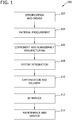
Figure 1 is a flow diagram of an aircraft production and service methodology. -
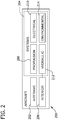
Figure 2 is a block diagram of an aircraft. -
Figure 3 is a side cross-sectional view of a cover plate that is inserted into an opening in one known fuel tank. -
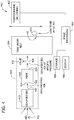
Figure 4 is a diagram of a system for putting dehumidified air into a tank under test and a thermographic imaging system. -
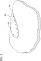
Figure 5 is an illustration of the cover plate ofFigure 3 attached to a tank under test. -
Figure 6 is an illustration of the cover plate and tank under test ofFigure 5 illustrating a thermographic image when dehumidified air within the tank passes through a leak and mixes with air of an increased humidity. - The embodiments described herein relate to the detection of leaks within pressurized vessels using infrared thermography to detect areas in which evaporated cooling is occurring. The described embodiments of the invention provide a method of leak detection on slightly pressurized aircraft fuel tanks (description in relation to vessels and cabins is by way of example only) without the use of hazardous substances or the application of indicators to detect a presence of such substances. The embodiments also address the problems associated with the testing of aircraft fuel tanks that are tested under relatively lower pressures, where the velocity flows emanated from leakage areas are so low that temperature changes are too low for stand alone infrared visualization or in situations where the leakages (and associated temperature changes) are masked and/or absorbed) by sealant, o-rings, or other forms of construction material.
- As mentioned above, evaporative cooling uses the natural relationship between relative humidity, water and air temperature and relative humidity is the actual vapor pressure to the pressure of saturated vapor of air at the prevailing dry bulb temperature and is an indication of the amount of water vapor that can be absorbed by the air until it reaches 100% relative humidity.
- In the context of an evaporative cooling/thermographic leak process, the air leaving the leakage area at a reduced water content (de-humidified to a lower relative humidity value or expelled into a higher humidity environment) has the capacity to absorb more water than the surrounding atmosphere external to the test piece. At the leakage areas (and external to the article under test) there exists a mixture zone where low relative humidity air passing through the leak area, with a velocity component, is mixed with stationary air of a higher relative humidity value, which causes evaporation of moisture from the stationary air. This localized evaporation of external air imparts a temperature drop proximate the leakage area that can be detected with an infrared camera.
- By using de-humidified air to pressurize the test piece (e.g., a fuel tank, aircraft cabin, or other vessel), the dependence on a velocity profile at the leakage area is significantly reduced as well as any influence that may be imparted by the material surrounding the leakage area which would otherwise mask actual leaks. In arid ambient environments, a humidity differential may be accomplished by adding humidity to a suspected leakage area.
- Referring more particularly to the drawings, embodiments of the disclosure may be described in the context of aircraft manufacturing and
service method 100 as shown inFigure 1 and anaircraft 200 as shown inFigure 2 . During pre-production, aircraft manufacturing andservice method 100 may include specification anddesign 102 ofaircraft 200 andmaterial procurement 104. - During production, component and
subassembly manufacturing 106 andsystem integration 108 ofaircraft 200 takes place. Thereafter,aircraft 200 may go through certification anddelivery 110 in order to be placed inservice 112. While in service by a customer,aircraft 200 is scheduled for routine maintenance and service 114 (which may also include modification, reconfiguration, refurbishment, and so on). - Each of the processes of aircraft manufacturing and
service method 100 may be performed or carried out by a system integrator, a third party, and/or an operator (e.g., a customer). For the purposes of this description, a system integrator may include, without limitation, any number of aircraft manufacturers and major-system subcontractors; a third party may include, for example, without limitation, any number of venders, subcontractors, and suppliers; and an operator may be an airline, leasing company, military entity, service organization, and so on. - As shown in
Figure 2 ,aircraft 200 produced by aircraft manufacturing andservice method 100 may includeairframe 202 with a plurality ofsystems 204 andinterior 206. Examples ofsystems 204 include one or more ofpropulsion system 208,electrical system 210,hydraulic system 212, andenvironmental system 214. Any number of other systems may be included in this example. Although an aerospace example is shown, the principles of the disclosure may be applied to other industries, such as the automotive, medical, food or petrochemical industry. - Apparatus and methods embodied herein may be employed during any one or more of the stages of aircraft manufacturing and
service method 100. For example, without limitation, components or subassemblies corresponding to component andsubassembly manufacturing 106 may be fabricated or manufactured in a manner similar to components or subassemblies produced whileaircraft 200 is in service. - Also, one or more apparatus embodiments, method embodiments, or a combination thereof may be utilized during component and
subassembly manufacturing 106 andsystem integration 108, for example, without limitation, by substantially expediting assembly of or reducing the cost ofaircraft 200. Similarly, one or more of apparatus embodiments, method embodiments, or a combination thereof may be utilized whileaircraft 200 is in service, for example, without limitation, to maintenance andservice 114 may be used duringsystem integration 108 and/or maintenance andservice 114 to determine whether parts may be connected and/or mated to each other. - The description of the different advantageous embodiments has been presented for purposes of illustration and description, and is not intended to be exhaustive or limited to the embodiments in the form disclosed. Many modifications and variations will be apparent to those of ordinary skill in the art. Further, different advantageous embodiments may provide different advantages as compared to other advantageous embodiments. The embodiment or embodiments selected are chosen and described in order to best explain the principles of the embodiments, the practical application, and to enable others of ordinary skill in the art to understand the disclosure for various embodiments with various modifications as are suited to the particular use contemplated.
-
Figure 3 is a side cross-sectional view of acover plate 300 that is inserted into anopening 302 in one knownfuel tank 304. In complex systems such as aircraft, a fuel tank is not simply a vessel with an opening for fuel insertion and another for fuel consumption. Rather, a fuel tank such asfuel tank 304 may include many openings where cover plates are utilized for the mounting of sensors or other components within the fuel tank. Additionally, certain fuel tanks are physically large in size which dictates that they be fabricated from multiple piece parts that are put together, for example through the use of mechanical fasteners and/or welding. While the cover plates are configured to form a seal between it and the tank under test, seals are known to fail, as are mechanical fasteners. Similarly, a welded area may include one or more voids within the welding zone that negate the sealing effect of welding. These issues dictate that such fuel tanks, as well as other vessels, and even the cabin of some aircraft, undergo leak testing as part of the manufacturing process. - Referring to
Figure 3 again,mechanical fasteners 310 are utilized in an attempt to form a seal betweencover plate 300 andfuel tank 304. Theopening 302 in the illustrated embodiment is an indented area that is sized for the insertion of thecover plate 300 and defines a sealingarea 312 between asurface 314 of thefuel tank 304 and asurface 316 of thecover plate 300. In a practical application, a sealer, an O-ring, or a gasket (neither shown inFigure 3 ) is utilized betweensurfaces secondary opening 320 may be included within thefuel tank 304 for the mounting of aninstrument 330.Instrument 330 represents any device that may be mounted within an opening on the material that makes up thefuel tank 304. -
Figure 4 is a diagram of asystem 400 for putting dehumidified air into a tank under test 402.System 400 includes adehumidifier 410 that receivesair 412, removes moisture from that air, thereby outputting dehumidifiedair 414 through anoutput 416 of thedehumidifier 410. As will be understood, during such a process, the ambient air within the tank under test has to be removed over time (e.g., displaced by the lower humidity air). According to the invention, the air drawn into thedehumidifier 410 is drawn from the tank 402, resulting in a quasi-closed loop humidity reduction system. - A
pump 420 may be included withinsystem 400 to receive the dehumidifiedair 414 at aninput 422 and pump the air through anoutput 424 of thepump 420 in order to maintain a desired pressure of dehumidified air within thetank 304. In operation, pump 420 supplies dehumidified air at apressure 426 totank 304. In embodiments, avalve 430 may be included that operates to maintain a pressure of the dehumidified air withintank 304 without operation of thepump 420 or thedehumidifier 410. - In
Figure 4 ,tank 304 is illustrated as having aleak 450. As described further in the following paragraphs, the reducedhumidity air 452 escapingtank 304 throughleak 450 will react with the air surrounding theleak 450 which is at a higher level of humidity. - More specifically, if reduced relative humidity air (dehumidified) is passed through an environment of higher relative humidity external to the leak location, the relative humidity will equalize somewhere between the two humidity values. This reaction imparts a temperature drop within the localized area of the
leak 450 as a result of evaporative cooling. As described further within, this evaporation and resulting decrease in temperature is sufficient to indicate leakage areas using infrared thermography, even such leaks are at very low pressure differentials (e.g., 0.25 psi). Such embodiments operate to remove a reliance on actual velocity values of escaping air at leakage areas in order to generate the temperature changes needed for the imaging process as well as masking of leakages that can occur due to absorption by sealants and gaskets. - Referring again to
Figure 4 , athermographic imaging system 460 includes a thermographic (infrared)camera 462, along with and for example, animage processing system 464 and may include one or both of adisplay 466 andstorage 468 for thermographic images. In operation, whenthermographic camera 462 is in the vicinity ofleak 450, thecamera 462 will be able to sense the temperature drop imparted by evaporative cooling as described herein andimage processing system 464 operates to provide data compatible for viewing ondisplay 466 and/or for storage withinstorage 468. -
Figure 5 is a mock thermographic illustration of thecover plate 300 ofFigure 3 attached to tank undertest 304 using a plurality offasteners 310. The embodiment illustrated byFigure 5 is an embodiment wherethermographic camera 462 does not sense any evaporative cooling occurring in the vicinity ofcover plate 300. On the other hand,Figure 6 is a mock thermographic illustration of thecover plate 300 andtank 304 which includes a leak 450 (also shown inFigure 4 ) which allows lower humidity air within thetank 304 to pass throughleak 450 and mix with air of an increased humidity outside of thetank 304. The result, as described herein, is anarea 600 of decreased temperature that has been sensed bythermographic camera 462.Area 600 may include several subareas within. For example, at an area closest to leak 450, animage 602 of alower temperature area 602 may be surrounded by an image of anarea 604 having a temperature between that ofarea 602 and that of thearea surrounding area 604. - To further illustrate the thermographic illustrations of
Figures 5 and6 , testing has been performed at various pressure differentials. For example, in one testing scenario a pressure differential between the exterior and interior of 6 psig (higher pressure in interior of tank being tested) resulted in a 0.6 degree C temperature differential between a leakage area and the same area when not leaking as sensed by the thermal imaging system. The temperature differential was also 0.6 degree C with a tank internal pressure of 4 psig. In further testing, the temperature differential was 0.5 degree C with a tank internal pressure of 2 psig, 0.5 psig, and 0.25 psig. A temperature differential was able to be discerned with a tank internal pressure of less than 0.25 psig as compared to the environment external to the tank under test. For reference, the temperature of the tank leakage area (prior to the initiation of leak testing) was about 19.5 degrees C, and as described above, once the leakage initiated evaporative cooling, the temperature in the leakage area was consistently reduced below 19 degrees C. As the testing results above illustrate, the evaporative cooling process described herein provides a capability to visualize leaks in tanks, vessels, and cabins down to less than a 0.25 psi pressure differential as well as the capability to identify leakage areas down to 20 microns in size. - Known infrared thermographic leak detection relies on a temperature change at the leakage areas. This temperature change is brought about as a result of a velocity increase of the pressurized air passing through the leakage areas. Previous research however, has shown that in many cases the pressure differential across the vessel under test, results in a very low velocity change in the air passing through such a leak, resulting in a temperature difference that is below the typical infrared detector threshold of 0.1 degrees C. However, introduction of evaporative cooling to such a process, as described herein, allows for the sensing of temperature changes that occur, even at such a low velocity.
- With the described embodiments, there is no need to use hazardous substances within a tank to be tested, or for the application of an indicator that reacts to the hazardous substance, and therefore no need for the subsequent removal of the indicator after testing of the tank. In addition, processes incorporating the described embodiments provide the ability to visualize leakage areas with a greater accuracy over tank testing processes than using helium and helium detectors. Helium and helium detectors only provide an approximation as to where leaks are located in a tank or other vessel. Further, the introduction of a humidity differential as described herein tends to reduce buildup of trapped moisture pockets within the vessel being tested. While described herein as using air with lower and higher humidity, embodiments which utilize gases other than air may be utilized, for example, nitrogen or other gases that can be humidified and dehumidified.
- Evaporative cooling combined with infrared thermographic imaging does not use any hazardous substances or chemicals and has no ongoing material running costs as compared to anhydrous ammonia/indicator or helium/helium detector methods. Evaporative cooling combined with infrared thermographic imaging produces superior results in the time it takes to use the helium/helium detector method and can provide leak testing/indication in less time that it takes to carry out an anhydrous ammonia/indicator leak test.
- Evaporative cooling combined with infrared thermographic imaging eliminates the ongoing use of hazardous chemicals, and thus eliminates most of the environmental impact that is found in other testing methodologies. In one example, detection is possible through the identification of 'made to measure' or modified air dehumidifiers upstream of the test article and the presence of infrared cameras.
- This written description uses examples to disclose various embodiments, which include the best mode, to enable any person skilled in the art to practice those embodiments, including making and using any devices or systems and performing any incorporated methods. The patentable scope is defined by the claims, and may include other examples that occur to those skilled in the art. Such other examples are intended to be within the scope of the claims if they have structural elements that do not differ from the literal language of the claims, or if they include equivalent structural elements with insubstantial differences from the literal languages of the claims.
Claims (9)
- A method for leak testing a commercial aircraft fuel tank comprising:providing an environment within the tank that is at a lower humidity than the environment surrounding the tank in which air drawn into a dehumidifier is drawn from the tank resulting in a quasi-closed loop humidity reduction system; andusing a thermographic imaging system to identify any leaks associated with the tank, based on evaporative cooling that occurs when a portion of the lower humidity environment escapes from the tank and mixes with the higher humidity environment surrounding the tank.
- The method according to Claim 1 wherein providing an environment within the tank comprises at least one of:reducing humidity of air being inserted into the tank; andincreasing humidity of the air in the area surrounding the tank.
- The method according to Claim 1 wherein providing an environment within the tank comprises providing an environment within the tank that is at a greater pressure than a pressure of the environment surrounding the tank.
- The method according to Claim 3 wherein the pressure within the tank is at least 0.25 psi greater than the pressure of the environment surrounding the tank.
- The method according to Claim 1 wherein using a thermographic imaging system to identify any leaks within the tank comprises identifying areas of lower temperature within a thermal image of a portion of the tank.
- The method according to Claim 1 wherein using a thermographic imaging system to identify any leaks associated with the tank comprises sensing a temperature drop caused by localized evaporation of external air proximate the leakage area.
- A system for testing a commercial aircraft fuel tank for leakages, said system comprising:at least one device for providing a humidity differential between an inside of the tank and the exterior of the tank in which air drawn into a dehumidifier is drawn from the tank resulting in a quasi-closed loop humidity reduction system; anda thermographic imaging system operable to identify any leaks associated with the tank, the leaks identifiable with said imaging system based on evaporative cooling that occurs when a portion of the lower humidity environment mixes with the higher humidity environment.
- The system according to Claim 7 wherein said thermographic imaging system comprises an image processing system operable for at least one of display and storage of images acquired by said thermographic imaging system.
- The system according to Claim 7 wherein said at least one device further comprises a pump operable for
increasing a pressure inside the tank to provide a pressure differential between the interior of the tank and the exterior of the tank.
Applications Claiming Priority (1)
| Application Number | Priority Date | Filing Date | Title |
|---|---|---|---|
| US12/697,411 US8539818B2 (en) | 2010-02-01 | 2010-02-01 | Methods and systems for evaporative cooling infrared thermographic leak detection |
Publications (3)
| Publication Number | Publication Date |
|---|---|
| EP2352003A2 EP2352003A2 (en) | 2011-08-03 |
| EP2352003A3 EP2352003A3 (en) | 2016-10-12 |
| EP2352003B1 true EP2352003B1 (en) | 2020-03-04 |
Family
ID=44059287
Family Applications (1)
| Application Number | Title | Priority Date | Filing Date |
|---|---|---|---|
| EP11151813.0A Active EP2352003B1 (en) | 2010-02-01 | 2011-01-24 | Methods and systems for evaporative cooling infrared thermographic leak detection |
Country Status (2)
| Country | Link |
|---|---|
| US (1) | US8539818B2 (en) |
| EP (1) | EP2352003B1 (en) |
Families Citing this family (13)
| Publication number | Priority date | Publication date | Assignee | Title |
|---|---|---|---|---|
| CN103575475A (en) * | 2012-08-09 | 2014-02-12 | 北汽福田汽车股份有限公司 | Vehicle sealing performance detecting device and method |
| US10373470B2 (en) | 2013-04-29 | 2019-08-06 | Intelliview Technologies, Inc. | Object detection |
| CA2847707C (en) | 2014-03-28 | 2021-03-30 | Intelliview Technologies Inc. | Leak detection |
| EP3137868B1 (en) * | 2014-04-29 | 2018-10-31 | SAIPEM S.p.A. | System and method for detection of hydrocarbon leakage from an underwater pipeline in a body of water and hydrocarbon extraction unit |
| US10943357B2 (en) | 2014-08-19 | 2021-03-09 | Intelliview Technologies Inc. | Video based indoor leak detection |
| JP6384352B2 (en) * | 2015-02-10 | 2018-09-05 | 株式会社デンソー | Abnormality diagnosis apparatus and abnormality diagnosis method |
| CN104848994B (en) * | 2015-04-17 | 2018-01-30 | 大连理工大学 | Valve leak detection system and method based on three dimensional temperature reconstruct |
| US10145788B2 (en) * | 2015-10-29 | 2018-12-04 | Konica Minolta, Inc. | Image processing device for gas detection, image processing method for gas detection and image processing program for gas detection |
| US11548161B2 (en) | 2020-05-14 | 2023-01-10 | The Boeing Company | Methods of performing a plurality of operations within a region of a part utilizing an end effector of a robot and robots that perform the methods |
| US12306638B2 (en) | 2020-11-18 | 2025-05-20 | The Boeing Company | Methods and scan systems for analyzing an object |
| US11639914B2 (en) | 2020-12-16 | 2023-05-02 | The Boeing Company | Non-destructive test systems with infrared thermography assemblies and ultrasonic test assemblies, and associated methods |
| CN113702419B (en) * | 2021-09-06 | 2024-05-07 | 浙江安胜科技股份有限公司 | Stainless steel vacuum vessel protection, identification and detection device and detection method |
| TWI903805B (en) * | 2024-10-14 | 2025-11-01 | 聯華電子股份有限公司 | Water leakage detection device and detection method thereof |
Citations (1)
| Publication number | Priority date | Publication date | Assignee | Title |
|---|---|---|---|---|
| US4745797A (en) * | 1984-05-07 | 1988-05-24 | Lockheed Corporation | Method and apparatus for detecting hydrocarbon fuel leaks |
Family Cites Families (6)
| Publication number | Priority date | Publication date | Assignee | Title |
|---|---|---|---|---|
| US5001346A (en) * | 1990-02-26 | 1991-03-19 | Rockwell International Corporation | Leak detection system with background compensation |
| US6401524B1 (en) * | 2000-12-08 | 2002-06-11 | The Goodyear Tire & Rubber Company | Method of detecting steam expansion vessel leakage |
| US6866089B2 (en) * | 2002-07-02 | 2005-03-15 | Carrier Corporation | Leak detection with thermal imaging |
| US7358860B2 (en) * | 2005-03-31 | 2008-04-15 | American Air Liquide, Inc. | Method and apparatus to monitor and detect cryogenic liquefied gas leaks |
| ITPD20060191A1 (en) | 2006-05-15 | 2007-11-16 | Consiglio Nazionale Ricerche | METHOD OF THERMOGRAPHIC DETECTION OF THERMO-HYGROMETRIC CONDITIONS OF LARGE AREAS |
| DE102008010619A1 (en) * | 2008-02-22 | 2009-08-27 | Bayerisches Zentrum für Angewandte Energieforschung e.V. | Leakage locating method for vacuum insulation panel, involves loading surface of evacuation system to be tested, with fluid, and measuring surface temperature, and detecting evaporative loss of fluid |
-
2010
- 2010-02-01 US US12/697,411 patent/US8539818B2/en active Active
-
2011
- 2011-01-24 EP EP11151813.0A patent/EP2352003B1/en active Active
Patent Citations (1)
| Publication number | Priority date | Publication date | Assignee | Title |
|---|---|---|---|---|
| US4745797A (en) * | 1984-05-07 | 1988-05-24 | Lockheed Corporation | Method and apparatus for detecting hydrocarbon fuel leaks |
Also Published As
| Publication number | Publication date |
|---|---|
| US20110185791A1 (en) | 2011-08-04 |
| EP2352003A2 (en) | 2011-08-03 |
| EP2352003A3 (en) | 2016-10-12 |
| US8539818B2 (en) | 2013-09-24 |
Similar Documents
| Publication | Publication Date | Title |
|---|---|---|
| EP2352003B1 (en) | Methods and systems for evaporative cooling infrared thermographic leak detection | |
| JP5783541B2 (en) | Leak inspection apparatus and leak inspection method | |
| US6067844A (en) | Nondestructive method for detection of defects and the condition of liners in polymer-lined pipes and equipment | |
| US4918975A (en) | Method and apparatus for testing fluid-filled systems for leaks | |
| US8167482B2 (en) | Thermography inspection of surface discontinuities | |
| US9746411B2 (en) | Apparatus and method for evaluating gas barrier properties | |
| US9097657B2 (en) | Leak detection of stator liquid cooling system | |
| US7454956B1 (en) | Heat exchanger leak detection using mass gas flow metering | |
| US9696251B2 (en) | Apparatus and method for evaluating gas barrier properties | |
| US20110310923A1 (en) | Method for non-destructive testing of at least partially open hollow components or system components for tightness in series production | |
| CN104406745A (en) | Portable flexible moist containing work medium leakage detection sticker and leakage detection method thereof | |
| Bergoglio et al. | Leak rate metrology for the society and industry | |
| US20180328810A1 (en) | Leak Detection with Oxygen | |
| KR20150133005A (en) | Lng cargo containment for gas leakage inspection device use balloon with gas reaction matter and its method, and this includes the lng carrier or lng offshore platform | |
| CN206095538U (en) | Pressure -bearing spare part leakproofness detection device under low temperature environment | |
| KR20230100517A (en) | Leakage inspection device for hydrogen gas containers | |
| RU2219508C2 (en) | Technique testing tightness of articles | |
| Blaufuß et al. | Proposed standards and methods for leak testing lithium-ion battery packs using glycol-based coolant with empirically derived rejection limits | |
| RU2322377C2 (en) | Device for in-flight finding faults in hydraulic line of manned space object temperature control system filled with working medium and method of operation of such device | |
| US11009493B2 (en) | Heat-sealable chemical vapor-sensor bag | |
| Große Bley | Methods of leak detection | |
| Anderson | Leak testing | |
| Walker et al. | Thermographic/Nondestructive Evaluation of the Space Shuttle Main Engine Nozzle | |
| RU2042108C1 (en) | Method of measurement of effective areas of leakages | |
| Lvovsky | NASA TECHNICAL STANDARD, NASA-STD-7012A, LEAK TEST REQUIREMENTS |
Legal Events
| Date | Code | Title | Description |
|---|---|---|---|
| PUAI | Public reference made under article 153(3) epc to a published international application that has entered the european phase |
Free format text: ORIGINAL CODE: 0009012 |
|
| 17P | Request for examination filed |
Effective date: 20110124 |
|
| AK | Designated contracting states |
Kind code of ref document: A2 Designated state(s): AL AT BE BG CH CY CZ DE DK EE ES FI FR GB GR HR HU IE IS IT LI LT LU LV MC MK MT NL NO PL PT RO RS SE SI SK SM TR |
|
| AX | Request for extension of the european patent |
Extension state: BA ME |
|
| PUAL | Search report despatched |
Free format text: ORIGINAL CODE: 0009013 |
|
| AK | Designated contracting states |
Kind code of ref document: A3 Designated state(s): AL AT BE BG CH CY CZ DE DK EE ES FI FR GB GR HR HU IE IS IT LI LT LU LV MC MK MT NL NO PL PT RO RS SE SI SK SM TR |
|
| AX | Request for extension of the european patent |
Extension state: BA ME |
|
| RIC1 | Information provided on ipc code assigned before grant |
Ipc: G01M 3/00 20060101AFI20160906BHEP Ipc: G01M 3/04 20060101ALI20160906BHEP Ipc: G01N 25/72 20060101ALI20160906BHEP |
|
| STAA | Information on the status of an ep patent application or granted ep patent |
Free format text: STATUS: EXAMINATION IS IN PROGRESS |
|
| 17Q | First examination report despatched |
Effective date: 20190408 |
|
| GRAP | Despatch of communication of intention to grant a patent |
Free format text: ORIGINAL CODE: EPIDOSNIGR1 |
|
| STAA | Information on the status of an ep patent application or granted ep patent |
Free format text: STATUS: GRANT OF PATENT IS INTENDED |
|
| INTG | Intention to grant announced |
Effective date: 20190816 |
|
| GRAS | Grant fee paid |
Free format text: ORIGINAL CODE: EPIDOSNIGR3 |
|
| GRAA | (expected) grant |
Free format text: ORIGINAL CODE: 0009210 |
|
| STAA | Information on the status of an ep patent application or granted ep patent |
Free format text: STATUS: THE PATENT HAS BEEN GRANTED |
|
| AK | Designated contracting states |
Kind code of ref document: B1 Designated state(s): AL AT BE BG CH CY CZ DE DK EE ES FI FR GB GR HR HU IE IS IT LI LT LU LV MC MK MT NL NO PL PT RO RS SE SI SK SM TR |
|
| REG | Reference to a national code |
Ref country code: GB Ref legal event code: FG4D |
|
| REG | Reference to a national code |
Ref country code: CH Ref legal event code: EP |
|
| REG | Reference to a national code |
Ref country code: AT Ref legal event code: REF Ref document number: 1240956 Country of ref document: AT Kind code of ref document: T Effective date: 20200315 |
|
| REG | Reference to a national code |
Ref country code: DE Ref legal event code: R096 Ref document number: 602011065329 Country of ref document: DE |
|
| REG | Reference to a national code |
Ref country code: IE Ref legal event code: FG4D |
|
| PG25 | Lapsed in a contracting state [announced via postgrant information from national office to epo] |
Ref country code: FI Free format text: LAPSE BECAUSE OF FAILURE TO SUBMIT A TRANSLATION OF THE DESCRIPTION OR TO PAY THE FEE WITHIN THE PRESCRIBED TIME-LIMIT Effective date: 20200304 Ref country code: NO Free format text: LAPSE BECAUSE OF FAILURE TO SUBMIT A TRANSLATION OF THE DESCRIPTION OR TO PAY THE FEE WITHIN THE PRESCRIBED TIME-LIMIT Effective date: 20200604 Ref country code: RS Free format text: LAPSE BECAUSE OF FAILURE TO SUBMIT A TRANSLATION OF THE DESCRIPTION OR TO PAY THE FEE WITHIN THE PRESCRIBED TIME-LIMIT Effective date: 20200304 |
|
| REG | Reference to a national code |
Ref country code: NL Ref legal event code: MP Effective date: 20200304 |
|
| PG25 | Lapsed in a contracting state [announced via postgrant information from national office to epo] |
Ref country code: BG Free format text: LAPSE BECAUSE OF FAILURE TO SUBMIT A TRANSLATION OF THE DESCRIPTION OR TO PAY THE FEE WITHIN THE PRESCRIBED TIME-LIMIT Effective date: 20200604 Ref country code: SE Free format text: LAPSE BECAUSE OF FAILURE TO SUBMIT A TRANSLATION OF THE DESCRIPTION OR TO PAY THE FEE WITHIN THE PRESCRIBED TIME-LIMIT Effective date: 20200304 Ref country code: HR Free format text: LAPSE BECAUSE OF FAILURE TO SUBMIT A TRANSLATION OF THE DESCRIPTION OR TO PAY THE FEE WITHIN THE PRESCRIBED TIME-LIMIT Effective date: 20200304 Ref country code: LV Free format text: LAPSE BECAUSE OF FAILURE TO SUBMIT A TRANSLATION OF THE DESCRIPTION OR TO PAY THE FEE WITHIN THE PRESCRIBED TIME-LIMIT Effective date: 20200304 Ref country code: GR Free format text: LAPSE BECAUSE OF FAILURE TO SUBMIT A TRANSLATION OF THE DESCRIPTION OR TO PAY THE FEE WITHIN THE PRESCRIBED TIME-LIMIT Effective date: 20200605 |
|
| REG | Reference to a national code |
Ref country code: LT Ref legal event code: MG4D |
|
| PG25 | Lapsed in a contracting state [announced via postgrant information from national office to epo] |
Ref country code: NL Free format text: LAPSE BECAUSE OF FAILURE TO SUBMIT A TRANSLATION OF THE DESCRIPTION OR TO PAY THE FEE WITHIN THE PRESCRIBED TIME-LIMIT Effective date: 20200304 |
|
| PG25 | Lapsed in a contracting state [announced via postgrant information from national office to epo] |
Ref country code: PT Free format text: LAPSE BECAUSE OF FAILURE TO SUBMIT A TRANSLATION OF THE DESCRIPTION OR TO PAY THE FEE WITHIN THE PRESCRIBED TIME-LIMIT Effective date: 20200729 Ref country code: SK Free format text: LAPSE BECAUSE OF FAILURE TO SUBMIT A TRANSLATION OF THE DESCRIPTION OR TO PAY THE FEE WITHIN THE PRESCRIBED TIME-LIMIT Effective date: 20200304 Ref country code: IS Free format text: LAPSE BECAUSE OF FAILURE TO SUBMIT A TRANSLATION OF THE DESCRIPTION OR TO PAY THE FEE WITHIN THE PRESCRIBED TIME-LIMIT Effective date: 20200704 Ref country code: RO Free format text: LAPSE BECAUSE OF FAILURE TO SUBMIT A TRANSLATION OF THE DESCRIPTION OR TO PAY THE FEE WITHIN THE PRESCRIBED TIME-LIMIT Effective date: 20200304 Ref country code: CZ Free format text: LAPSE BECAUSE OF FAILURE TO SUBMIT A TRANSLATION OF THE DESCRIPTION OR TO PAY THE FEE WITHIN THE PRESCRIBED TIME-LIMIT Effective date: 20200304 Ref country code: LT Free format text: LAPSE BECAUSE OF FAILURE TO SUBMIT A TRANSLATION OF THE DESCRIPTION OR TO PAY THE FEE WITHIN THE PRESCRIBED TIME-LIMIT Effective date: 20200304 Ref country code: ES Free format text: LAPSE BECAUSE OF FAILURE TO SUBMIT A TRANSLATION OF THE DESCRIPTION OR TO PAY THE FEE WITHIN THE PRESCRIBED TIME-LIMIT Effective date: 20200304 Ref country code: SM Free format text: LAPSE BECAUSE OF FAILURE TO SUBMIT A TRANSLATION OF THE DESCRIPTION OR TO PAY THE FEE WITHIN THE PRESCRIBED TIME-LIMIT Effective date: 20200304 Ref country code: EE Free format text: LAPSE BECAUSE OF FAILURE TO SUBMIT A TRANSLATION OF THE DESCRIPTION OR TO PAY THE FEE WITHIN THE PRESCRIBED TIME-LIMIT Effective date: 20200304 |
|
| REG | Reference to a national code |
Ref country code: AT Ref legal event code: MK05 Ref document number: 1240956 Country of ref document: AT Kind code of ref document: T Effective date: 20200304 |
|
| REG | Reference to a national code |
Ref country code: DE Ref legal event code: R097 Ref document number: 602011065329 Country of ref document: DE |
|
| PLBE | No opposition filed within time limit |
Free format text: ORIGINAL CODE: 0009261 |
|
| STAA | Information on the status of an ep patent application or granted ep patent |
Free format text: STATUS: NO OPPOSITION FILED WITHIN TIME LIMIT |
|
| PG25 | Lapsed in a contracting state [announced via postgrant information from national office to epo] |
Ref country code: AT Free format text: LAPSE BECAUSE OF FAILURE TO SUBMIT A TRANSLATION OF THE DESCRIPTION OR TO PAY THE FEE WITHIN THE PRESCRIBED TIME-LIMIT Effective date: 20200304 Ref country code: DK Free format text: LAPSE BECAUSE OF FAILURE TO SUBMIT A TRANSLATION OF THE DESCRIPTION OR TO PAY THE FEE WITHIN THE PRESCRIBED TIME-LIMIT Effective date: 20200304 Ref country code: IT Free format text: LAPSE BECAUSE OF FAILURE TO SUBMIT A TRANSLATION OF THE DESCRIPTION OR TO PAY THE FEE WITHIN THE PRESCRIBED TIME-LIMIT Effective date: 20200304 |
|
| 26N | No opposition filed |
Effective date: 20201207 |
|
| PG25 | Lapsed in a contracting state [announced via postgrant information from national office to epo] |
Ref country code: PL Free format text: LAPSE BECAUSE OF FAILURE TO SUBMIT A TRANSLATION OF THE DESCRIPTION OR TO PAY THE FEE WITHIN THE PRESCRIBED TIME-LIMIT Effective date: 20200304 Ref country code: SI Free format text: LAPSE BECAUSE OF FAILURE TO SUBMIT A TRANSLATION OF THE DESCRIPTION OR TO PAY THE FEE WITHIN THE PRESCRIBED TIME-LIMIT Effective date: 20200304 |
|
| PG25 | Lapsed in a contracting state [announced via postgrant information from national office to epo] |
Ref country code: MC Free format text: LAPSE BECAUSE OF FAILURE TO SUBMIT A TRANSLATION OF THE DESCRIPTION OR TO PAY THE FEE WITHIN THE PRESCRIBED TIME-LIMIT Effective date: 20200304 |
|
| REG | Reference to a national code |
Ref country code: CH Ref legal event code: PL |
|
| PG25 | Lapsed in a contracting state [announced via postgrant information from national office to epo] |
Ref country code: LU Free format text: LAPSE BECAUSE OF NON-PAYMENT OF DUE FEES Effective date: 20210124 |
|
| REG | Reference to a national code |
Ref country code: BE Ref legal event code: MM Effective date: 20210131 |
|
| PG25 | Lapsed in a contracting state [announced via postgrant information from national office to epo] |
Ref country code: LI Free format text: LAPSE BECAUSE OF NON-PAYMENT OF DUE FEES Effective date: 20210131 Ref country code: CH Free format text: LAPSE BECAUSE OF NON-PAYMENT OF DUE FEES Effective date: 20210131 |
|
| PG25 | Lapsed in a contracting state [announced via postgrant information from national office to epo] |
Ref country code: IE Free format text: LAPSE BECAUSE OF NON-PAYMENT OF DUE FEES Effective date: 20210124 |
|
| PG25 | Lapsed in a contracting state [announced via postgrant information from national office to epo] |
Ref country code: BE Free format text: LAPSE BECAUSE OF NON-PAYMENT OF DUE FEES Effective date: 20210131 |
|
| PG25 | Lapsed in a contracting state [announced via postgrant information from national office to epo] |
Ref country code: HU Free format text: LAPSE BECAUSE OF FAILURE TO SUBMIT A TRANSLATION OF THE DESCRIPTION OR TO PAY THE FEE WITHIN THE PRESCRIBED TIME-LIMIT; INVALID AB INITIO Effective date: 20110124 Ref country code: CY Free format text: LAPSE BECAUSE OF FAILURE TO SUBMIT A TRANSLATION OF THE DESCRIPTION OR TO PAY THE FEE WITHIN THE PRESCRIBED TIME-LIMIT Effective date: 20200304 |
|
| P01 | Opt-out of the competence of the unified patent court (upc) registered |
Effective date: 20230516 |
|
| PG25 | Lapsed in a contracting state [announced via postgrant information from national office to epo] |
Ref country code: MK Free format text: LAPSE BECAUSE OF FAILURE TO SUBMIT A TRANSLATION OF THE DESCRIPTION OR TO PAY THE FEE WITHIN THE PRESCRIBED TIME-LIMIT Effective date: 20200304 |
|
| PG25 | Lapsed in a contracting state [announced via postgrant information from national office to epo] |
Ref country code: TR Free format text: LAPSE BECAUSE OF FAILURE TO SUBMIT A TRANSLATION OF THE DESCRIPTION OR TO PAY THE FEE WITHIN THE PRESCRIBED TIME-LIMIT Effective date: 20200304 |
|
| PG25 | Lapsed in a contracting state [announced via postgrant information from national office to epo] |
Ref country code: MT Free format text: LAPSE BECAUSE OF FAILURE TO SUBMIT A TRANSLATION OF THE DESCRIPTION OR TO PAY THE FEE WITHIN THE PRESCRIBED TIME-LIMIT Effective date: 20200304 |
|
| PGFP | Annual fee paid to national office [announced via postgrant information from national office to epo] |
Ref country code: GB Payment date: 20260127 Year of fee payment: 16 |
|
| PGFP | Annual fee paid to national office [announced via postgrant information from national office to epo] |
Ref country code: DE Payment date: 20260128 Year of fee payment: 16 |
|
| PGFP | Annual fee paid to national office [announced via postgrant information from national office to epo] |
Ref country code: FR Payment date: 20260126 Year of fee payment: 16 |