EP2352308A2 - Appareil et procédé de reconnaissance d'assemblage d'écouteur dans un terminal portable - Google Patents
Appareil et procédé de reconnaissance d'assemblage d'écouteur dans un terminal portable Download PDFInfo
- Publication number
- EP2352308A2 EP2352308A2 EP10194102A EP10194102A EP2352308A2 EP 2352308 A2 EP2352308 A2 EP 2352308A2 EP 10194102 A EP10194102 A EP 10194102A EP 10194102 A EP10194102 A EP 10194102A EP 2352308 A2 EP2352308 A2 EP 2352308A2
- Authority
- EP
- European Patent Office
- Prior art keywords
- terminal
- earphone
- earphone plug
- detector
- portable terminal
- Prior art date
- Legal status (The legal status is an assumption and is not a legal conclusion. Google has not performed a legal analysis and makes no representation as to the accuracy of the status listed.)
- Granted
Links
Images


Classifications
-
- H—ELECTRICITY
- H01—ELECTRIC ELEMENTS
- H01R—ELECTRICALLY-CONDUCTIVE CONNECTIONS; STRUCTURAL ASSOCIATIONS OF A PLURALITY OF MUTUALLY-INSULATED ELECTRICAL CONNECTING ELEMENTS; COUPLING DEVICES; CURRENT COLLECTORS
- H01R31/00—Coupling parts supported only by co-operation with counterpart
- H01R31/08—Short-circuiting members for bridging contacts in a counterpart
-
- H—ELECTRICITY
- H04—ELECTRIC COMMUNICATION TECHNIQUE
- H04R—LOUDSPEAKERS, MICROPHONES, GRAMOPHONE PICK-UPS OR LIKE ACOUSTIC ELECTROMECHANICAL TRANSDUCERS; ELECTRIC HEARING AIDS; PUBLIC ADDRESS SYSTEMS
- H04R1/00—Details of transducers, loudspeakers or microphones
- H04R1/10—Earpieces; Attachments therefor ; Earphones; Monophonic headphones
- H04R1/1041—Mechanical or electronic switches, or control elements
-
- H—ELECTRICITY
- H01—ELECTRIC ELEMENTS
- H01R—ELECTRICALLY-CONDUCTIVE CONNECTIONS; STRUCTURAL ASSOCIATIONS OF A PLURALITY OF MUTUALLY-INSULATED ELECTRICAL CONNECTING ELEMENTS; COUPLING DEVICES; CURRENT COLLECTORS
- H01R13/00—Details of coupling devices of the kinds covered by groups H01R12/70 or H01R24/00 - H01R33/00
- H01R13/64—Means for preventing incorrect coupling
- H01R13/641—Means for preventing incorrect coupling by indicating incorrect coupling; by indicating correct or full engagement
-
- H—ELECTRICITY
- H01—ELECTRIC ELEMENTS
- H01R—ELECTRICALLY-CONDUCTIVE CONNECTIONS; STRUCTURAL ASSOCIATIONS OF A PLURALITY OF MUTUALLY-INSULATED ELECTRICAL CONNECTING ELEMENTS; COUPLING DEVICES; CURRENT COLLECTORS
- H01R24/00—Two-part coupling devices, or either of their cooperating parts, characterised by their overall structure
- H01R24/58—Contacts spaced along longitudinal axis of engagement
-
- H—ELECTRICITY
- H04—ELECTRIC COMMUNICATION TECHNIQUE
- H04B—TRANSMISSION
- H04B1/00—Details of transmission systems, not covered by a single one of groups H04B3/00 - H04B13/00; Details of transmission systems not characterised by the medium used for transmission
- H04B1/38—Transceivers, i.e. devices in which transmitter and receiver form a structural unit and in which at least one part is used for functions of transmitting and receiving
- H04B1/40—Circuits
-
- H—ELECTRICITY
- H04—ELECTRIC COMMUNICATION TECHNIQUE
- H04M—TELEPHONIC COMMUNICATION
- H04M1/00—Substation equipment, e.g. for use by subscribers
- H04M1/60—Substation equipment, e.g. for use by subscribers including speech amplifiers
- H04M1/6033—Substation equipment, e.g. for use by subscribers including speech amplifiers for providing handsfree use or a loudspeaker mode in telephone sets
- H04M1/6041—Portable telephones adapted for handsfree use
- H04M1/6058—Portable telephones adapted for handsfree use involving the use of a headset accessory device connected to the portable telephone
-
- H—ELECTRICITY
- H01—ELECTRIC ELEMENTS
- H01R—ELECTRICALLY-CONDUCTIVE CONNECTIONS; STRUCTURAL ASSOCIATIONS OF A PLURALITY OF MUTUALLY-INSULATED ELECTRICAL CONNECTING ELEMENTS; COUPLING DEVICES; CURRENT COLLECTORS
- H01R2105/00—Three poles
-
- H—ELECTRICITY
- H01—ELECTRIC ELEMENTS
- H01R—ELECTRICALLY-CONDUCTIVE CONNECTIONS; STRUCTURAL ASSOCIATIONS OF A PLURALITY OF MUTUALLY-INSULATED ELECTRICAL CONNECTING ELEMENTS; COUPLING DEVICES; CURRENT COLLECTORS
- H01R2107/00—Four or more poles
-
- H—ELECTRICITY
- H04—ELECTRIC COMMUNICATION TECHNIQUE
- H04R—LOUDSPEAKERS, MICROPHONES, GRAMOPHONE PICK-UPS OR LIKE ACOUSTIC ELECTROMECHANICAL TRANSDUCERS; ELECTRIC HEARING AIDS; PUBLIC ADDRESS SYSTEMS
- H04R2420/00—Details of connection covered by H04R, not provided for in its groups
- H04R2420/05—Detection of connection of loudspeakers or headphones to amplifiers
-
- H—ELECTRICITY
- H04—ELECTRIC COMMUNICATION TECHNIQUE
- H04R—LOUDSPEAKERS, MICROPHONES, GRAMOPHONE PICK-UPS OR LIKE ACOUSTIC ELECTROMECHANICAL TRANSDUCERS; ELECTRIC HEARING AIDS; PUBLIC ADDRESS SYSTEMS
- H04R2420/00—Details of connection covered by H04R, not provided for in its groups
- H04R2420/09—Applications of special connectors, e.g. USB, XLR, in loudspeakers, microphones or headphones
-
- H—ELECTRICITY
- H04—ELECTRIC COMMUNICATION TECHNIQUE
- H04R—LOUDSPEAKERS, MICROPHONES, GRAMOPHONE PICK-UPS OR LIKE ACOUSTIC ELECTROMECHANICAL TRANSDUCERS; ELECTRIC HEARING AIDS; PUBLIC ADDRESS SYSTEMS
- H04R5/00—Stereophonic arrangements
- H04R5/04—Circuit arrangements, e.g. for selective connection of amplifier inputs/outputs to loudspeakers, for loudspeaker detection, or for adaptation of settings to personal preferences or hearing impairments
Definitions
- the present invention relates to an external output apparatus and method for a portable terminal. More particularly, the present invention relates to an apparatus and method for improving the performance of a determination of whether an earphone is mounted to a portable terminal.
- portable terminals have now evolved into multimedia devices that provide various functions and services, such as a phone book function, a game function, a Short Message Service (SMS), an Electronic (E)-mail service, a morning call function, a Motion Picture Expert Group (MPEG)-1 or MPEG-2 Audio Layer-3 (MP3) function, a scheduling function, a digital camera function, an Internet service, and the like.
- SMS Short Message Service
- E Electronic
- MPEG Motion Picture Expert Group
- MP3 MPEG-2 Audio Layer-3
- portable terminals with multimedia player functions such as a moving picture player function and an MP3 player function
- multimedia player functions such as a moving picture player function and an MP3 player function
- portable terminals are provided with earphone capabilities in order to prevent such inconvenience.
- users of portable terminals can receive music and audio services through earphones coupled to the portable terminals without causing inconvenience to other people and can receive call services through a speaker and a microphone of the earphones even when the users cannot hold the portable terminals to receive the call services.
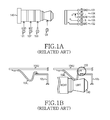
- FIGs. 1A and 1B are diagrams illustrating a process of mounting an earphone in a portable terminal according to the related art.
- FIG. 1A is a diagram illustrating an earphone plug and an earphone plug receptacle of a portable terminal according to the related art.
- the earphone plug receptacle of the portable terminal supports a 4-pole earphone plug.
- the earphone plug receptacle includes a second terminal 101 that is a common ground terminal, a third terminal 102 that is a microphone terminal, a fourth terminal 103 that is a right sound terminal, and a fifth terminal 104 that is a left sound terminal.
- the second to fifth terminals 101, 102, 103 and 104 contact the corresponding poles of the earphone plug 140.
- a sixth terminal 105 that serves as a switch terminal of the earphone plug receptacle is connected to the fifth terminal 104 (i.e., the left sound terminal), so that the portable terminal determines that the earphone is not mounted.
- the ground terminal 101, the microphone terminal 102, the right sound terminal 103, and the left sound terminal 104 contact the corresponding poles of the earphone plug 140.
- FIG. 1B is a diagram illustrating a state where an earphone plug is mounted/dismounted on/from an earphone plug receptacle of a portable terminal according to the related art.
- the fifth terminal 104 (i.e., the left sound terminal) includes a lower portion 104L and an upper portion 104U.
- the lower portion 104L and an upper portion 104U may always remain in contact with each other or may only come into contact with each other when the earphone plug 140 is mounted in the earphone plug receptacle.
- the lower portion 104L of the fifth terminal 104 is not in contact with the sixth terminal 105 (i.e., the switching terminal) as shown in the area denoted by 150.
- the lower portion 104L of the fifth terminal 104 may be in contact with the upper portion 104U of the fifth terminal 104.
- the comparator When the fifth terminal 104 and the sixth terminal 105 are connected to a comparator (not illustrated) and the fifth terminal 104 and the sixth terminal 105 are not in contact as shown in the area denoted by 150, the comparator generates a low signal to recognize that the earphone is mounted.
- FIG. 1B illustrates the state where the earphone plug 140 is not mounted in the earphone plug receptacle and the lower portion 104L of the fifth terminal 104 is in contact the sixth terminal 105.
- the lower portion 104L of the fifth terminal 104 is not in contact with the sixth terminal 105.
- the lower portion 104L of the fifth terminal 104 may be in contact with the upper portion 104U of the fifth terminal 104.
- the portable terminal determines if the earphone plug is mounted by detecting whether there is contact between the fifth terminal 104 and the sixth terminal 105. However, if foreign substances are caught between the fifth and sixth terminals, the portable terminal determines that the earphone plug is mounted and operates the portable terminal in an earphone mode instead of performing a speaker output operation.
- An aspect of the present invention is to address at least the above-mentioned problems and/or disadvantages and to provide at least the advantages below. Accordingly, an aspect of the present invention is to provide an apparatus and method for improving a determination of whether an earphone is mounted to a portable terminal.
- Another aspect of the present invention is to provide an apparatus and method for determining if an earphone is mounted to a portable terminal without using a comparator, thus reducing the unit production cost.
- Another aspect of the present invention is to provide an apparatus and method for providing a structure for preventing a foreign substance from being caught in a terminal for determining if an earphone is mounted to a portable terminal.
- an apparatus for recognizing whether an earphone is mounted to a portable terminal includes a common ground terminal and a switching terminal of an earphone plug receptacle for electrically connecting to each other and the same pole of an earphone plug when the earphone plug is mounted in the earphone plug receptacle, and an external output managing unit for generating an earphone mounting notification signal through a detector.
- a method for recognizing whether an earphone is mounted to a portable terminal includes electrically connecting a common ground terminal and a switching terminal of an earphone plug receptacle to each other and the same pole of an earphone plug when the earphone plug is mounted in the earphone plug receptacle, and generating an earphone mounting notification signal through a detector.
- FIG. 1A is a diagram illustrating an earphone plug and an earphone plug receptacle of a portable terminal according to the related art
- FIG. 1B is a diagram illustrating a state where an earphone plug is mounted/dismounted on/from an earphone plug receptacle of a portable terminal according to the related art
- FIG. 2 is a block diagram illustrating a configuration of a portable terminal for determining if an earphone is mounted to the portable terminal according to an exemplary embodiment of the present invention
- FIG. 3A is a diagram illustrating an earphone plug receptacle of a portable terminal and an earphone plug, according to an exemplary embodiment of the present invention
- FIG. 3B is a diagram illustrating a state where an earphone plug is mounted in an earphone plug receptacle of a portable terminal according to an exemplary embodiment of the present invention.
- FIG. 4 is a flow diagram illustrating a process for determining if an earphone is mounted to a portable terminal according to an exemplary embodiment of the present invention.
- connection or “contact” as used herein may refer to an electrical connection or an electrical contact in addition to or instead of a mechanical connection or a mechanical contact.
- an electrical connection or an electrical contact may occur through an electrically conductive medium.
- Exemplary embodiments of the present invention provide an apparatus and method for improving the performance of a determination of whether an earphone is mounted to a portable terminal, such as a portable terminal supporting a 3.5 mm earphone plug.
- the earphone outputs sounds generated by the portable terminal, and includes external output devices such as an external speaker and a microphone.
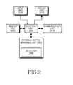
- FIG. 2 is a block diagram illustrating a configuration of a portable terminal for determining if an earphone is mounted to the portable terminal according to an exemplary embodiment of the present invention
- the portable terminal may include a control unit 200, an external output managing unit 202, a memory unit 206, an input unit 208, a display unit 210, and a communication unit 212.
- the external output managing unit 202 may include a detector 204.
- the portable terminal may include additional units that are not illustrated here merely for sake of conciseness. Similarly, the functionality of two or more of the above units may be integrated into a single component.
- the portable terminal includes an earphone plug receptacle where the second terminal (i.e., the common ground terminal) and the sixth terminal (i.e., the switching terminal) are connected to the same pole line of an earphone plug, and the microphone terminal and the left and right sound terminals are connected in the same manner as the portable terminal of the related art.
- the second terminal i.e., the common ground terminal
- the sixth terminal i.e., the switching terminal
- the control unit 200 of the portable terminal controls overall operations of the portable terminal. For example, the control unit 200 processes and controls voice communication and data communication.
- the control unit 200 determines that the earphone plug is mounted in the earphone plug receptacle of the portable terminal.
- the control unit 200 determines that the earphone plug is not mounted in the earphone plug receptacle of the portable terminal.
- the external output managing unit 202 includes an earphone plug receptacle capable of having the earphone plug mounted therein.
- the earphone plug receptacle has the second terminal (i.e., the common ground terminal) and the sixth terminal (i.e., the switching terminal) that are connected to the same pole line of the earphone plug, and the microphone terminal and the left and right sound terminals that are connected in the same manner as with the portable terminal of the related art.
- the external output managing unit 202 includes the detector 204 with the switching terminal.
- the detector 204 generates a low signal when the common ground terminal contacts the switching terminal (that is, when the earphone plug is mounted in the earphone plug receptacle).
- the external output managing unit 202 via the detector 204, generates a high signal when the common ground terminal does not contact the switching terminal (that is, when the earphone plug is not mounted in the earphone plug receptacle).
- the external output managing unit 202 can determine if an earphone is mounted by determining whether the signal of the detector 204 is in a high state or a low state.
- the detector 204 of the external output managing unit 202 generates signals according to the earphone mounting/dismounting states. According to an exemplary embodiment of the present invention, the detector 204 is connected to the switching terminal. When the earphone plug is mounted on the earphone plug receptacle, the detector 204 generates the low signal. On the other hand, when the earphone plug is disconnected from the earphone plug receptacle, the detector 204 generates the high signal.
- the memory unit 206 includes, for example, Read-Only Memory (ROM), Random-Access Memory (RAM), flash ROM, and the like.
- ROM stores a variety of reference data and microcode (i.e., code) of a program for the process and control of the control unit 200 and the external output managing unit 202.
- the RAM is a working memory of the control unit 200, which stores temporary data that are generated during the execution of various programs.
- the flash ROM stores a variety of updatable data such as a phone book, an outgoing message, and an incoming message.
- the input unit 208 numeric keys of digits 0-9 and a plurality of function keys, such as a Menu key, a Cancel (delete) key, a Confirmation key, a Talk key, an End key, an Internet connection key, Navigation keys (or Direction keys), character input key, and the like.
- the input unit 208 provides the control unit 200 with key input data that corresponds to a key pressed by a user.
- the display unit 210 displays numerals and characters, moving pictures, still pictures and status information generated during an operation of the portable terminal.
- the display unit 210 may be a color Liquid Crystal Display (LCD), an Active Mode Organic Light Emitting Diode (AMOLED), and the like. If the display unit 210 has a touch input device and is applied to a touch input type portable terminal, it can be used as an input device.
- LCD Liquid Crystal Display
- AMOLED Active Mode Organic Light Emitting Diode
- the communication unit 212 transmits/receives Radio Frequency (RF) signals inputted/outputted through an antenna (not illustrated). For example, in a transmitting (TX) mode, the communication unit 212 channel-encodes, spreads and RF-processes TX data prior to transmission. In a receiving (RX) mode, the communication unit 212 converts a received RF signal into a baseband signal and despreads and channel-decodes the baseband signal to restore the original data.
- TX transmitting
- RX receiving
- the control unit 200 of the portable terminal may also be configured to perform the functions of the external output managing unit 202. Although separate units are provided for respective functions of the control unit 200, the control unit 200 may also be configured to perform all or some of the functions on behalf of such separate units.
- FIGs. 3A and 3B are diagrams illustrating a process for mounting an earphone in a portable terminal according to an exemplary embodiment of the present invention.
- FIG. 3A is a diagram illustrating an earphone plug receptacle of a portable terminal and an earphone plug, according to an exemplary embodiment of the present invention.
- a second terminal 301 i.e., the common ground terminal
- a sixth terminal 305 i.e., the switching terminal
- a microphone terminal 302 and left and right sound terminals 304 and 303 are connected in the same manner as that of the portable terminal of the related art.
- the switching terminal 305 and the common ground terminal 301 are connected to the same pole line of the earphone plug 320 and the microphone terminal 302 and the left and right sound terminals 304 and 303 are connected to the corresponding pole lines.
- the portable terminal can determine if an earphone is mounted according to the connection/disconnection of the ground terminal 301 and the switching terminal 305 which together are shown in the area denoted by 306.
- FIG. 3B is a diagram illustrating a state where an earphone plug is mounted in an earphone plug receptacle of a portable terminal according to an exemplary embodiment of the present invention.
- the sixth terminal i.e., the switching terminal
- the second terminal i.e., the common ground terminal
- the portable terminal can determine whether an earphone is mounted according to whether there is contact between the second terminal and the sixth terminal.
- FIG. 4 is a flow diagram illustrating a process for determining if an earphone is mounted to a portable terminal according to an exemplary embodiment of the present invention.
- the portable terminal detects a terminal for a determination of whether an earphone is connected.
- the sixth terminal 305 i.e., the switching terminal
- the second terminal 301 i.e., the ground terminal.
- the ground terminal 301 includes a detector that detects a high signal or a low signal according to the connection/disconnection with the sixth terminal 305 (i.e., the switching terminal).
- the sixth terminal 305 i.e., the switching terminal
- the second terminal 301 i.e., the ground terminal
- the sixth terminal 305 and the second terminal 301 are not connected to each other and thus the signal of the detector is high.
- the portable terminal determines whether the sixth terminal 305 (i.e., the switching terminal) and the second terminal 301 (i.e., the ground terminal) are connected to each other and the same pole of the earphone plug 320.
- step 403 If the sixth terminal 305 (i.e., the switching terminal) and the second terminal 301 (i.e., the ground terminal) are connected to each other and the same pole of the earphone plug 320 in step 403, the portable terminal proceeds to step 405.
- step 405 the signal of the detector connected to the second terminal 401 (i.e., the ground terminal) is the low level.
- step 407 the portable terminal determines whether the signal of the detector changed from the high level to the low level.
- the portable terminal determines whether the sixth terminal 305 (i.e., the switching terminal) and the second terminal 301 (i.e., the ground terminal) are connected to each other after having been disconnected from each other (that is, the signal of the detector changed from the high level to the low level), or whether the sixth terminal 305 (i.e., the switching terminal) and the second terminal 301 (i.e., the ground terminal) remain in a connected state (that is, the signal of the detector maintains the low level).
- the sixth terminal 305 i.e., the switching terminal
- the second terminal 301 i.e., the ground terminal
- the portable terminal returns to step 403. This is to determine if there are any state changes when the earphone continues to be mounted to the portable terminal.
- step 407 the portable terminal determines that the sixth terminal 305 (i.e., the switching terminal) and the second terminal 301 (i.e., the ground terminal) are connected to each other after having been disconnected from each other in step 407. If the portable terminal determines that the sixth terminal 305 (i.e., the switching terminal) and the second terminal 301 (i.e., the ground terminal) are connected to each other after having been disconnected from each other in step 407, the portable terminal proceeds to step 409. In step 409, the portable terminal determines that the earphone is mounted to the portable terminal after having been disconnected from the portable terminal.
- step 403 the portable terminal proceeds to step 411.
- the signal of the detector connected to the second terminal 301 i.e., the ground terminal
- step 413 the portable terminal determines whether the signal of the detector changed from the low level to the high level.
- the portable terminal determines whether the sixth terminal 305 (i.e., the switching terminal) and the second terminal 301 (i.e., the ground terminal) are disconnected from each other after having been connected to each other (that is, the signal of the detector changes from the low level to the high level), or whether the sixth terminal 305 (i.e., the switching terminal) and the second terminal 301 (i.e., the ground terminal) remain in a disconnected state (that is, the signal of the detector maintains the high level).
- the sixth terminal 305 i.e., the switching terminal
- the second terminal 301 i.e., the ground terminal
- the portable terminal returns to step 403. This is to determine if there are any state changes when the earphone continues to be dismounted from the portable terminal.
- step 415 the portable terminal determines that the earphone is dismounted after having been mounted to the portable terminal.
- the portable terminal ends the algorithm according to an exemplary embodiment of the present invention.
- exemplary embodiments of the present invention provide an apparatus and method for improving the performance of a determination of whether an earphone is mounted to a portable terminal, such as a portable terminal supporting a 3.5 mm earphone plug.
- exemplary embodiments of the present invention use an earphone plug with a structure for preventing foreign substances from being caught therein without using a comparator mounted on a portable terminal, thereby making it possible to reduce the unit production cost of a portable terminal and improve the earphone recognition rate.
Landscapes
- Engineering & Computer Science (AREA)
- Signal Processing (AREA)
- Physics & Mathematics (AREA)
- Acoustics & Sound (AREA)
- Computer Networks & Wireless Communication (AREA)
- Headphones And Earphones (AREA)
- Telephone Function (AREA)
- Telephone Set Structure (AREA)
- Stereophonic Arrangements (AREA)
- Circuit For Audible Band Transducer (AREA)
Applications Claiming Priority (1)
| Application Number | Priority Date | Filing Date | Title |
|---|---|---|---|
| KR1020090120884A KR101651122B1 (ko) | 2009-12-08 | 2009-12-08 | 휴대용 단말기에서 이어폰 장착을 인식하기 위한 장치 및 방법 |
Publications (3)
| Publication Number | Publication Date |
|---|---|
| EP2352308A2 true EP2352308A2 (fr) | 2011-08-03 |
| EP2352308A3 EP2352308A3 (fr) | 2011-09-14 |
| EP2352308B1 EP2352308B1 (fr) | 2017-08-23 |
Family
ID=43661889
Family Applications (1)
| Application Number | Title | Priority Date | Filing Date |
|---|---|---|---|
| EP10194102.9A Not-in-force EP2352308B1 (fr) | 2009-12-08 | 2010-12-08 | Appareil et procédé pour reconnaître le montage d'écouteurs dans un terminal portable |
Country Status (5)
| Country | Link |
|---|---|
| US (1) | US9380371B2 (fr) |
| EP (1) | EP2352308B1 (fr) |
| JP (1) | JP5740145B2 (fr) |
| KR (1) | KR101651122B1 (fr) |
| CN (1) | CN102088512B (fr) |
Cited By (1)
| Publication number | Priority date | Publication date | Assignee | Title |
|---|---|---|---|---|
| CN104023101A (zh) * | 2014-06-17 | 2014-09-03 | 深圳市中兴移动通信有限公司 | 一种移动终端及其基于开关型耳机座的天线切换方法 |
Families Citing this family (15)
| Publication number | Priority date | Publication date | Assignee | Title |
|---|---|---|---|---|
| KR101636771B1 (ko) * | 2010-03-05 | 2016-07-06 | 삼성전자주식회사 | 휴대용 단말기에서 이어폰 인식 회로 장치 및 방법 |
| TWI505582B (zh) * | 2010-10-29 | 2015-10-21 | Fih Hong Kong Ltd | 耳機介面電路及具有該耳機介面電路之行動電話 |
| KR20120068274A (ko) * | 2010-12-17 | 2012-06-27 | 삼성전자주식회사 | 휴대 단말기의 통합 커넥터 장치 및 이의 운용 방법 |
| KR101469545B1 (ko) | 2011-09-06 | 2014-12-05 | 삼성전자주식회사 | 오디오 신호 처리 방법 및 그에 따른 오디오 신호 처리 장치 |
| KR101937839B1 (ko) * | 2012-08-29 | 2019-04-10 | 삼성전자 주식회사 | 이어폰 접속 인터페이스 및 이를 포함하는 단말기와 단말기 운용 방법 |
| WO2014088202A1 (fr) * | 2012-12-04 | 2014-06-12 | (주)다하미랩 | Système de traitement du son qui reconnaît des écouteurs de terminal mobile à l'aide d'un motif sonore, procédé de reconnaissance d'écouteurs de terminal mobile, et procédé de traitement d'un son d'entrée à l'aide de celui-ci, procédé de conversion automatique d'une sortie d'amplification de signal audio sur la base d'un ensemble écouteurs/microphone, et support d'enregistrement lisible par ordinateur |
| KR101442027B1 (ko) * | 2013-04-29 | 2014-09-25 | (주)다하미 커뮤니케이션즈 | 음향패턴을 이용하여 휴대형 단말기용 이어폰 인식하는 음향처리 시스템, 음향패턴을 이용한 휴대형 단말기용 이어폰 인식방법 및 이를 이용한 입력음향 처리 방법. |
| KR102127622B1 (ko) * | 2013-04-30 | 2020-06-29 | 삼성전자 주식회사 | 음성 입력 경로 제어방법 및 이를 지원하는 장치 |
| CN103414042A (zh) * | 2013-07-25 | 2013-11-27 | 苏州三星电子电脑有限公司 | 四段式耳机接口及具有该接口的笔记本电脑 |
| CN105959845B (zh) * | 2014-01-09 | 2019-03-01 | 北京奇虎科技有限公司 | 基于耳机插座的外接设备识别电路、方法、装置和系统 |
| GB2527487B (en) * | 2014-03-25 | 2019-10-16 | Ifpl Group Ltd | Headphone socket |
| KR20170017475A (ko) * | 2015-08-07 | 2017-02-15 | 엘지전자 주식회사 | 이어폰, 그와 연결 가능한 이동 단말기 및 제어 방법 |
| KR102482656B1 (ko) | 2016-07-14 | 2022-12-29 | 삼성전자주식회사 | 이어폰을 이용한 전자 장치의 제어 방법 및 이를 위한 전자 장치 |
| US11047925B2 (en) * | 2018-11-29 | 2021-06-29 | Sony Interactive Entertainment Inc. | Split ground connector |
| CN116195145B (zh) * | 2020-08-19 | 2026-04-24 | 杜比实验室特许公司 | 用户可配置的音频扩音器 |
Family Cites Families (16)
| Publication number | Priority date | Publication date | Assignee | Title |
|---|---|---|---|---|
| JPH11162574A (ja) * | 1997-11-27 | 1999-06-18 | Canon Inc | プラグ識別装置 |
| JPH11288766A (ja) * | 1998-04-01 | 1999-10-19 | Matsushita Electric Ind Co Ltd | プラグ挿入検知装置 |
| JP3398699B2 (ja) | 1999-12-14 | 2003-04-21 | 埼玉日本電気株式会社 | 携帯端末装置 |
| JP2002076982A (ja) * | 2000-08-29 | 2002-03-15 | Nec Saitama Ltd | 携帯通信装置 |
| JP2002141980A (ja) * | 2000-10-31 | 2002-05-17 | Kyocera Corp | 携帯電話装置の信号系切替制御方法及び装置 |
| KR100422475B1 (ko) * | 2001-09-25 | 2004-03-11 | 에스케이텔레텍주식회사 | 이어잭에 접속되는 스피커모듈과 이를 이용한 통화방법 |
| KR100396267B1 (ko) * | 2001-10-24 | 2003-09-02 | 삼성전자주식회사 | 통신 단말기에서 이어마이크로폰 상태 확인 방법 |
| JP2003204592A (ja) * | 2002-01-07 | 2003-07-18 | Mitsubishi Electric Corp | オーディオ |
| KR100871260B1 (ko) * | 2002-08-24 | 2008-11-28 | 삼성전자주식회사 | 이어잭 플러그 연결 여부 검출 장치 |
| TW595239B (en) * | 2003-01-28 | 2004-06-21 | Htc Corp | Detection circuit to detect the earphone type plugged into the insertion hole |
| US20060013410A1 (en) * | 2004-04-20 | 2006-01-19 | Wurtz Michael J | Mobile-telephone adapters for automatic-noise-reduction headphones |
| KR100677433B1 (ko) * | 2005-02-11 | 2007-02-02 | 엘지전자 주식회사 | 이동 통신 단말기의 모노 및 스테레오 음원 출력 장치 |
| US7912501B2 (en) * | 2007-01-05 | 2011-03-22 | Apple Inc. | Audio I/O headset plug and plug detection circuitry |
| TWI368360B (en) * | 2008-12-31 | 2012-07-11 | Htc Corp | Portable electric apparatus and jack connection method therefor |
| KR101568301B1 (ko) * | 2009-08-21 | 2015-11-20 | 삼성전자주식회사 | 휴대용 단말기에서 오디오 채널 간 크로스 톡 개선 장치 및 방법 |
| KR101719302B1 (ko) * | 2010-01-08 | 2017-03-23 | 삼성전자주식회사 | 이어플러그 인식을 위한 이어잭 |
-
2009
- 2009-12-08 KR KR1020090120884A patent/KR101651122B1/ko not_active Expired - Fee Related
-
2010
- 2010-12-08 CN CN201010586287.2A patent/CN102088512B/zh not_active Expired - Fee Related
- 2010-12-08 EP EP10194102.9A patent/EP2352308B1/fr not_active Not-in-force
- 2010-12-08 JP JP2010273590A patent/JP5740145B2/ja not_active Expired - Fee Related
- 2010-12-08 US US12/962,933 patent/US9380371B2/en not_active Expired - Fee Related
Non-Patent Citations (1)
| Title |
|---|
| None |
Cited By (1)
| Publication number | Priority date | Publication date | Assignee | Title |
|---|---|---|---|---|
| CN104023101A (zh) * | 2014-06-17 | 2014-09-03 | 深圳市中兴移动通信有限公司 | 一种移动终端及其基于开关型耳机座的天线切换方法 |
Also Published As
| Publication number | Publication date |
|---|---|
| CN102088512B (zh) | 2015-01-14 |
| US20110135109A1 (en) | 2011-06-09 |
| JP5740145B2 (ja) | 2015-06-24 |
| KR101651122B1 (ko) | 2016-08-26 |
| EP2352308B1 (fr) | 2017-08-23 |
| US9380371B2 (en) | 2016-06-28 |
| KR20110064339A (ko) | 2011-06-15 |
| EP2352308A3 (fr) | 2011-09-14 |
| JP2011125015A (ja) | 2011-06-23 |
| CN102088512A (zh) | 2011-06-08 |
Similar Documents
| Publication | Publication Date | Title |
|---|---|---|
| US9380371B2 (en) | Apparatus and method for recognizing earphone mounting in portable terminal | |
| US9179233B2 (en) | Apparatus and method for interfacing earphone | |
| EP3860305B1 (fr) | Terminal mobile, appareil d'affichage et son procédé de commande | |
| US8548175B2 (en) | Method for recognizing ear phone in portable terminal and apparatus thereof | |
| US8155337B2 (en) | Compatible circuit and method for 4- and 5-pole earphones and portable device using the same | |
| EP3641283A1 (fr) | Appareil et procédé de commande du microphone intégré d'un terminal portable | |
| US9059792B2 (en) | Noise removal method and system | |
| KR20130066880A (ko) | 이어폰 접속 검출 시스템 및 이를 지원하는 단말기 | |
| CN108494464A (zh) | 天线控制方法、天线组件、电子设备及存储介质 | |
| CN105704106B (zh) | 一种可视化ivr实现方法及移动终端 | |
| CN103458114A (zh) | 一种切换多媒体流的方法、装备及终端 | |
| US20110124321A1 (en) | Apparatus and method for changing communication mode in mobile terminal | |
| EP2284718A1 (fr) | Appareil et procédé pour déterminer le type d'accessoire dans un terminal portable | |
| CN113132440A (zh) | 一种音频传输方法、音频传输系统及电子设备 | |
| US7836218B2 (en) | System and method for recognizing external device by portable terminal | |
| US20090111336A1 (en) | Split connector and method | |
| JP2009010587A (ja) | 接続端部切り替え装置および接続端部切り替え方法 | |
| KR100827803B1 (ko) | 초광대역 무선 통신 모듈을 포함하는 이동통신 단말기 및이의 구동 방법 | |
| CN112118031B (zh) | 语音交互装置及其控制方法、设备和计算机存储介质 | |
| CN104010017A (zh) | 终端设备和用于其的信息处理方法 | |
| US20060286999A1 (en) | Wireless communication terminal with external mike sensing function and method thereof | |
| KR20040061715A (ko) | 무선통신 단말기용 레이저 포인터 | |
| CN106816923A (zh) | 一种无线原装适配器识别的方法及终端 | |
| CN105049593A (zh) | 一种通话方法和终端 | |
| KR20090047616A (ko) | 소프트웨어 업그레이드 수행을 위한 시스템 및 방법 |
Legal Events
| Date | Code | Title | Description |
|---|---|---|---|
| PUAI | Public reference made under article 153(3) epc to a published international application that has entered the european phase |
Free format text: ORIGINAL CODE: 0009012 |
|
| AK | Designated contracting states |
Kind code of ref document: A2 Designated state(s): AL AT BE BG CH CY CZ DE DK EE ES FI FR GB GR HR HU IE IS IT LI LT LU LV MC MK MT NL NO PL PT RO RS SE SI SK SM TR |
|
| AX | Request for extension of the european patent |
Extension state: BA ME |
|
| PUAL | Search report despatched |
Free format text: ORIGINAL CODE: 0009013 |
|
| AK | Designated contracting states |
Kind code of ref document: A3 Designated state(s): AL AT BE BG CH CY CZ DE DK EE ES FI FR GB GR HR HU IE IS IT LI LT LU LV MC MK MT NL NO PL PT RO RS SE SI SK SM TR |
|
| AX | Request for extension of the european patent |
Extension state: BA ME |
|
| RIC1 | Information provided on ipc code assigned before grant |
Ipc: H04R 1/10 20060101AFI20110808BHEP Ipc: H04R 5/04 20060101ALN20110808BHEP Ipc: H04M 1/60 20060101ALI20110808BHEP |
|
| 17P | Request for examination filed |
Effective date: 20120314 |
|
| RAP1 | Party data changed (applicant data changed or rights of an application transferred) |
Owner name: SAMSUNG ELECTRONICS CO., LTD. |
|
| 17Q | First examination report despatched |
Effective date: 20160630 |
|
| GRAP | Despatch of communication of intention to grant a patent |
Free format text: ORIGINAL CODE: EPIDOSNIGR1 |
|
| RIC1 | Information provided on ipc code assigned before grant |
Ipc: H01R 107/00 20060101ALN20170224BHEP Ipc: H01R 13/641 20060101ALI20170224BHEP Ipc: H04R 1/10 20060101AFI20170224BHEP Ipc: H04R 5/04 20060101ALN20170224BHEP Ipc: H01R 105/00 20060101ALN20170224BHEP Ipc: H01R 24/58 20110101ALI20170224BHEP Ipc: H04M 1/60 20060101ALI20170224BHEP |
|
| INTG | Intention to grant announced |
Effective date: 20170316 |
|
| GRAS | Grant fee paid |
Free format text: ORIGINAL CODE: EPIDOSNIGR3 |
|
| GRAA | (expected) grant |
Free format text: ORIGINAL CODE: 0009210 |
|
| AK | Designated contracting states |
Kind code of ref document: B1 Designated state(s): AL AT BE BG CH CY CZ DE DK EE ES FI FR GB GR HR HU IE IS IT LI LT LU LV MC MK MT NL NO PL PT RO RS SE SI SK SM TR |
|
| REG | Reference to a national code |
Ref country code: GB Ref legal event code: FG4D |
|
| REG | Reference to a national code |
Ref country code: CH Ref legal event code: EP |
|
| REG | Reference to a national code |
Ref country code: AT Ref legal event code: REF Ref document number: 922501 Country of ref document: AT Kind code of ref document: T Effective date: 20170915 |
|
| REG | Reference to a national code |
Ref country code: IE Ref legal event code: FG4D |
|
| REG | Reference to a national code |
Ref country code: DE Ref legal event code: R096 Ref document number: 602010044574 Country of ref document: DE |
|
| REG | Reference to a national code |
Ref country code: NL Ref legal event code: MP Effective date: 20170823 |
|
| REG | Reference to a national code |
Ref country code: LT Ref legal event code: MG4D |
|
| REG | Reference to a national code |
Ref country code: AT Ref legal event code: MK05 Ref document number: 922501 Country of ref document: AT Kind code of ref document: T Effective date: 20170823 |
|
| PG25 | Lapsed in a contracting state [announced via postgrant information from national office to epo] |
Ref country code: AT Free format text: LAPSE BECAUSE OF FAILURE TO SUBMIT A TRANSLATION OF THE DESCRIPTION OR TO PAY THE FEE WITHIN THE PRESCRIBED TIME-LIMIT Effective date: 20170823 Ref country code: FI Free format text: LAPSE BECAUSE OF FAILURE TO SUBMIT A TRANSLATION OF THE DESCRIPTION OR TO PAY THE FEE WITHIN THE PRESCRIBED TIME-LIMIT Effective date: 20170823 Ref country code: NL Free format text: LAPSE BECAUSE OF FAILURE TO SUBMIT A TRANSLATION OF THE DESCRIPTION OR TO PAY THE FEE WITHIN THE PRESCRIBED TIME-LIMIT Effective date: 20170823 Ref country code: HR Free format text: LAPSE BECAUSE OF FAILURE TO SUBMIT A TRANSLATION OF THE DESCRIPTION OR TO PAY THE FEE WITHIN THE PRESCRIBED TIME-LIMIT Effective date: 20170823 Ref country code: SE Free format text: LAPSE BECAUSE OF FAILURE TO SUBMIT A TRANSLATION OF THE DESCRIPTION OR TO PAY THE FEE WITHIN THE PRESCRIBED TIME-LIMIT Effective date: 20170823 Ref country code: LT Free format text: LAPSE BECAUSE OF FAILURE TO SUBMIT A TRANSLATION OF THE DESCRIPTION OR TO PAY THE FEE WITHIN THE PRESCRIBED TIME-LIMIT Effective date: 20170823 Ref country code: NO Free format text: LAPSE BECAUSE OF FAILURE TO SUBMIT A TRANSLATION OF THE DESCRIPTION OR TO PAY THE FEE WITHIN THE PRESCRIBED TIME-LIMIT Effective date: 20171123 |
|
| PG25 | Lapsed in a contracting state [announced via postgrant information from national office to epo] |
Ref country code: RS Free format text: LAPSE BECAUSE OF FAILURE TO SUBMIT A TRANSLATION OF THE DESCRIPTION OR TO PAY THE FEE WITHIN THE PRESCRIBED TIME-LIMIT Effective date: 20170823 Ref country code: PL Free format text: LAPSE BECAUSE OF FAILURE TO SUBMIT A TRANSLATION OF THE DESCRIPTION OR TO PAY THE FEE WITHIN THE PRESCRIBED TIME-LIMIT Effective date: 20170823 Ref country code: LV Free format text: LAPSE BECAUSE OF FAILURE TO SUBMIT A TRANSLATION OF THE DESCRIPTION OR TO PAY THE FEE WITHIN THE PRESCRIBED TIME-LIMIT Effective date: 20170823 Ref country code: BG Free format text: LAPSE BECAUSE OF FAILURE TO SUBMIT A TRANSLATION OF THE DESCRIPTION OR TO PAY THE FEE WITHIN THE PRESCRIBED TIME-LIMIT Effective date: 20171123 Ref country code: IS Free format text: LAPSE BECAUSE OF FAILURE TO SUBMIT A TRANSLATION OF THE DESCRIPTION OR TO PAY THE FEE WITHIN THE PRESCRIBED TIME-LIMIT Effective date: 20171223 Ref country code: ES Free format text: LAPSE BECAUSE OF FAILURE TO SUBMIT A TRANSLATION OF THE DESCRIPTION OR TO PAY THE FEE WITHIN THE PRESCRIBED TIME-LIMIT Effective date: 20170823 Ref country code: GR Free format text: LAPSE BECAUSE OF FAILURE TO SUBMIT A TRANSLATION OF THE DESCRIPTION OR TO PAY THE FEE WITHIN THE PRESCRIBED TIME-LIMIT Effective date: 20171124 |
|
| PG25 | Lapsed in a contracting state [announced via postgrant information from national office to epo] |
Ref country code: CZ Free format text: LAPSE BECAUSE OF FAILURE TO SUBMIT A TRANSLATION OF THE DESCRIPTION OR TO PAY THE FEE WITHIN THE PRESCRIBED TIME-LIMIT Effective date: 20170823 Ref country code: RO Free format text: LAPSE BECAUSE OF FAILURE TO SUBMIT A TRANSLATION OF THE DESCRIPTION OR TO PAY THE FEE WITHIN THE PRESCRIBED TIME-LIMIT Effective date: 20170823 Ref country code: DK Free format text: LAPSE BECAUSE OF FAILURE TO SUBMIT A TRANSLATION OF THE DESCRIPTION OR TO PAY THE FEE WITHIN THE PRESCRIBED TIME-LIMIT Effective date: 20170823 |
|
| REG | Reference to a national code |
Ref country code: DE Ref legal event code: R097 Ref document number: 602010044574 Country of ref document: DE |
|
| PG25 | Lapsed in a contracting state [announced via postgrant information from national office to epo] |
Ref country code: EE Free format text: LAPSE BECAUSE OF FAILURE TO SUBMIT A TRANSLATION OF THE DESCRIPTION OR TO PAY THE FEE WITHIN THE PRESCRIBED TIME-LIMIT Effective date: 20170823 Ref country code: SM Free format text: LAPSE BECAUSE OF FAILURE TO SUBMIT A TRANSLATION OF THE DESCRIPTION OR TO PAY THE FEE WITHIN THE PRESCRIBED TIME-LIMIT Effective date: 20170823 Ref country code: SK Free format text: LAPSE BECAUSE OF FAILURE TO SUBMIT A TRANSLATION OF THE DESCRIPTION OR TO PAY THE FEE WITHIN THE PRESCRIBED TIME-LIMIT Effective date: 20170823 Ref country code: IT Free format text: LAPSE BECAUSE OF FAILURE TO SUBMIT A TRANSLATION OF THE DESCRIPTION OR TO PAY THE FEE WITHIN THE PRESCRIBED TIME-LIMIT Effective date: 20170823 |
|
| PLBE | No opposition filed within time limit |
Free format text: ORIGINAL CODE: 0009261 |
|
| STAA | Information on the status of an ep patent application or granted ep patent |
Free format text: STATUS: NO OPPOSITION FILED WITHIN TIME LIMIT |
|
| REG | Reference to a national code |
Ref country code: CH Ref legal event code: PL |
|
| 26N | No opposition filed |
Effective date: 20180524 |
|
| PG25 | Lapsed in a contracting state [announced via postgrant information from national office to epo] |
Ref country code: SI Free format text: LAPSE BECAUSE OF FAILURE TO SUBMIT A TRANSLATION OF THE DESCRIPTION OR TO PAY THE FEE WITHIN THE PRESCRIBED TIME-LIMIT Effective date: 20170823 |
|
| REG | Reference to a national code |
Ref country code: IE Ref legal event code: MM4A |
|
| PG25 | Lapsed in a contracting state [announced via postgrant information from national office to epo] |
Ref country code: LU Free format text: LAPSE BECAUSE OF NON-PAYMENT OF DUE FEES Effective date: 20171208 Ref country code: MT Free format text: LAPSE BECAUSE OF NON-PAYMENT OF DUE FEES Effective date: 20171208 |
|
| REG | Reference to a national code |
Ref country code: FR Ref legal event code: ST Effective date: 20180831 |
|
| REG | Reference to a national code |
Ref country code: BE Ref legal event code: MM Effective date: 20171231 |
|
| PG25 | Lapsed in a contracting state [announced via postgrant information from national office to epo] |
Ref country code: FR Free format text: LAPSE BECAUSE OF NON-PAYMENT OF DUE FEES Effective date: 20180102 Ref country code: IE Free format text: LAPSE BECAUSE OF NON-PAYMENT OF DUE FEES Effective date: 20171208 |
|
| PG25 | Lapsed in a contracting state [announced via postgrant information from national office to epo] |
Ref country code: BE Free format text: LAPSE BECAUSE OF NON-PAYMENT OF DUE FEES Effective date: 20171231 Ref country code: LI Free format text: LAPSE BECAUSE OF NON-PAYMENT OF DUE FEES Effective date: 20171231 Ref country code: CH Free format text: LAPSE BECAUSE OF NON-PAYMENT OF DUE FEES Effective date: 20171231 |
|
| PG25 | Lapsed in a contracting state [announced via postgrant information from national office to epo] |
Ref country code: MC Free format text: LAPSE BECAUSE OF FAILURE TO SUBMIT A TRANSLATION OF THE DESCRIPTION OR TO PAY THE FEE WITHIN THE PRESCRIBED TIME-LIMIT Effective date: 20170823 Ref country code: HU Free format text: LAPSE BECAUSE OF FAILURE TO SUBMIT A TRANSLATION OF THE DESCRIPTION OR TO PAY THE FEE WITHIN THE PRESCRIBED TIME-LIMIT; INVALID AB INITIO Effective date: 20101208 |
|
| PG25 | Lapsed in a contracting state [announced via postgrant information from national office to epo] |
Ref country code: CY Free format text: LAPSE BECAUSE OF NON-PAYMENT OF DUE FEES Effective date: 20170823 |
|
| PG25 | Lapsed in a contracting state [announced via postgrant information from national office to epo] |
Ref country code: MK Free format text: LAPSE BECAUSE OF FAILURE TO SUBMIT A TRANSLATION OF THE DESCRIPTION OR TO PAY THE FEE WITHIN THE PRESCRIBED TIME-LIMIT Effective date: 20170823 |
|
| PG25 | Lapsed in a contracting state [announced via postgrant information from national office to epo] |
Ref country code: TR Free format text: LAPSE BECAUSE OF FAILURE TO SUBMIT A TRANSLATION OF THE DESCRIPTION OR TO PAY THE FEE WITHIN THE PRESCRIBED TIME-LIMIT Effective date: 20170823 |
|
| PG25 | Lapsed in a contracting state [announced via postgrant information from national office to epo] |
Ref country code: PT Free format text: LAPSE BECAUSE OF FAILURE TO SUBMIT A TRANSLATION OF THE DESCRIPTION OR TO PAY THE FEE WITHIN THE PRESCRIBED TIME-LIMIT Effective date: 20170823 |
|
| PG25 | Lapsed in a contracting state [announced via postgrant information from national office to epo] |
Ref country code: AL Free format text: LAPSE BECAUSE OF FAILURE TO SUBMIT A TRANSLATION OF THE DESCRIPTION OR TO PAY THE FEE WITHIN THE PRESCRIBED TIME-LIMIT Effective date: 20170823 |
|
| PGFP | Annual fee paid to national office [announced via postgrant information from national office to epo] |
Ref country code: DE Payment date: 20201120 Year of fee payment: 11 Ref country code: GB Payment date: 20201125 Year of fee payment: 11 |
|
| REG | Reference to a national code |
Ref country code: DE Ref legal event code: R119 Ref document number: 602010044574 Country of ref document: DE |
|
| GBPC | Gb: european patent ceased through non-payment of renewal fee |
Effective date: 20211208 |
|
| PG25 | Lapsed in a contracting state [announced via postgrant information from national office to epo] |
Ref country code: GB Free format text: LAPSE BECAUSE OF NON-PAYMENT OF DUE FEES Effective date: 20211208 Ref country code: DE Free format text: LAPSE BECAUSE OF NON-PAYMENT OF DUE FEES Effective date: 20220701 |