EP2352590B1 - Mikrofluidische multiplexierte zellen- und molekülanalysevorrichtung und entsprechendes verfahren - Google Patents
Mikrofluidische multiplexierte zellen- und molekülanalysevorrichtung und entsprechendes verfahren Download PDFInfo
- Publication number
- EP2352590B1 EP2352590B1 EP09783921.1A EP09783921A EP2352590B1 EP 2352590 B1 EP2352590 B1 EP 2352590B1 EP 09783921 A EP09783921 A EP 09783921A EP 2352590 B1 EP2352590 B1 EP 2352590B1
- Authority
- EP
- European Patent Office
- Prior art keywords
- fluid
- capture chamber
- chamber
- capture
- particles
- Prior art date
- Legal status (The legal status is an assumption and is not a legal conclusion. Google has not performed a legal analysis and makes no representation as to the accuracy of the status listed.)
- Not-in-force
Links
Images







Classifications
-
- B—PERFORMING OPERATIONS; TRANSPORTING
- B81—MICROSTRUCTURAL TECHNOLOGY
- B81B—MICROSTRUCTURAL DEVICES OR SYSTEMS, e.g. MICROMECHANICAL DEVICES
- B81B1/00—Devices without movable or flexible elements, e.g. microcapillary devices
-
- B—PERFORMING OPERATIONS; TRANSPORTING
- B01—PHYSICAL OR CHEMICAL PROCESSES OR APPARATUS IN GENERAL
- B01L—CHEMICAL OR PHYSICAL LABORATORY APPARATUS FOR GENERAL USE
- B01L3/00—Containers or dishes for laboratory use, e.g. laboratory glassware; Droppers
- B01L3/50—Containers for the purpose of retaining a material to be analysed, e.g. test tubes
- B01L3/502—Containers for the purpose of retaining a material to be analysed, e.g. test tubes with fluid transport, e.g. in multi-compartment structures
- B01L3/5027—Containers for the purpose of retaining a material to be analysed, e.g. test tubes with fluid transport, e.g. in multi-compartment structures by integrated microfluidic structures, i.e. dimensions of channels and chambers are such that surface tension forces are important, e.g. lab-on-a-chip
- B01L3/50273—Containers for the purpose of retaining a material to be analysed, e.g. test tubes with fluid transport, e.g. in multi-compartment structures by integrated microfluidic structures, i.e. dimensions of channels and chambers are such that surface tension forces are important, e.g. lab-on-a-chip characterised by the means or forces applied to move the fluids
-
- B—PERFORMING OPERATIONS; TRANSPORTING
- B01—PHYSICAL OR CHEMICAL PROCESSES OR APPARATUS IN GENERAL
- B01L—CHEMICAL OR PHYSICAL LABORATORY APPARATUS FOR GENERAL USE
- B01L3/00—Containers or dishes for laboratory use, e.g. laboratory glassware; Droppers
- B01L3/50—Containers for the purpose of retaining a material to be analysed, e.g. test tubes
- B01L3/502—Containers for the purpose of retaining a material to be analysed, e.g. test tubes with fluid transport, e.g. in multi-compartment structures
- B01L3/5027—Containers for the purpose of retaining a material to be analysed, e.g. test tubes with fluid transport, e.g. in multi-compartment structures by integrated microfluidic structures, i.e. dimensions of channels and chambers are such that surface tension forces are important, e.g. lab-on-a-chip
- B01L3/502761—Containers for the purpose of retaining a material to be analysed, e.g. test tubes with fluid transport, e.g. in multi-compartment structures by integrated microfluidic structures, i.e. dimensions of channels and chambers are such that surface tension forces are important, e.g. lab-on-a-chip specially adapted for handling suspended solids or molecules independently from the bulk fluid flow, e.g. for trapping or sorting beads or physically stretching molecules
-
- B—PERFORMING OPERATIONS; TRANSPORTING
- B01—PHYSICAL OR CHEMICAL PROCESSES OR APPARATUS IN GENERAL
- B01L—CHEMICAL OR PHYSICAL LABORATORY APPARATUS FOR GENERAL USE
- B01L2200/00—Solutions for specific problems relating to chemical or physical laboratory apparatus
- B01L2200/02—Adapting objects or devices to another
- B01L2200/026—Fluid interfacing between devices or objects, e.g. connectors, inlet details
- B01L2200/027—Fluid interfacing between devices or objects, e.g. connectors, inlet details for microfluidic devices
-
- B—PERFORMING OPERATIONS; TRANSPORTING
- B01—PHYSICAL OR CHEMICAL PROCESSES OR APPARATUS IN GENERAL
- B01L—CHEMICAL OR PHYSICAL LABORATORY APPARATUS FOR GENERAL USE
- B01L2200/00—Solutions for specific problems relating to chemical or physical laboratory apparatus
- B01L2200/06—Fluid handling related problems
- B01L2200/0647—Handling flowable solids, e.g. microscopic beads, cells, particles
-
- B—PERFORMING OPERATIONS; TRANSPORTING
- B01—PHYSICAL OR CHEMICAL PROCESSES OR APPARATUS IN GENERAL
- B01L—CHEMICAL OR PHYSICAL LABORATORY APPARATUS FOR GENERAL USE
- B01L2200/00—Solutions for specific problems relating to chemical or physical laboratory apparatus
- B01L2200/06—Fluid handling related problems
- B01L2200/0647—Handling flowable solids, e.g. microscopic beads, cells, particles
- B01L2200/0668—Trapping microscopic beads
-
- B—PERFORMING OPERATIONS; TRANSPORTING
- B01—PHYSICAL OR CHEMICAL PROCESSES OR APPARATUS IN GENERAL
- B01L—CHEMICAL OR PHYSICAL LABORATORY APPARATUS FOR GENERAL USE
- B01L2200/00—Solutions for specific problems relating to chemical or physical laboratory apparatus
- B01L2200/10—Integrating sample preparation and analysis in single entity, e.g. lab-on-a-chip concept
-
- B—PERFORMING OPERATIONS; TRANSPORTING
- B01—PHYSICAL OR CHEMICAL PROCESSES OR APPARATUS IN GENERAL
- B01L—CHEMICAL OR PHYSICAL LABORATORY APPARATUS FOR GENERAL USE
- B01L2300/00—Additional constructional details
- B01L2300/08—Geometry, shape and general structure
- B01L2300/0809—Geometry, shape and general structure rectangular shaped
- B01L2300/0816—Cards, e.g. flat sample carriers usually with flow in two horizontal directions
-
- B—PERFORMING OPERATIONS; TRANSPORTING
- B01—PHYSICAL OR CHEMICAL PROCESSES OR APPARATUS IN GENERAL
- B01L—CHEMICAL OR PHYSICAL LABORATORY APPARATUS FOR GENERAL USE
- B01L2300/00—Additional constructional details
- B01L2300/08—Geometry, shape and general structure
- B01L2300/0848—Specific forms of parts of containers
- B01L2300/0851—Bottom walls
-
- B—PERFORMING OPERATIONS; TRANSPORTING
- B01—PHYSICAL OR CHEMICAL PROCESSES OR APPARATUS IN GENERAL
- B01L—CHEMICAL OR PHYSICAL LABORATORY APPARATUS FOR GENERAL USE
- B01L2300/00—Additional constructional details
- B01L2300/08—Geometry, shape and general structure
- B01L2300/0887—Laminated structure
-
- B—PERFORMING OPERATIONS; TRANSPORTING
- B01—PHYSICAL OR CHEMICAL PROCESSES OR APPARATUS IN GENERAL
- B01L—CHEMICAL OR PHYSICAL LABORATORY APPARATUS FOR GENERAL USE
- B01L2400/00—Moving or stopping fluids
- B01L2400/04—Moving fluids with specific forces or mechanical means
- B01L2400/0403—Moving fluids with specific forces or mechanical means specific forces
- B01L2400/0457—Moving fluids with specific forces or mechanical means specific forces passive flow or gravitation
-
- B—PERFORMING OPERATIONS; TRANSPORTING
- B01—PHYSICAL OR CHEMICAL PROCESSES OR APPARATUS IN GENERAL
- B01L—CHEMICAL OR PHYSICAL LABORATORY APPARATUS FOR GENERAL USE
- B01L2400/00—Moving or stopping fluids
- B01L2400/04—Moving fluids with specific forces or mechanical means
- B01L2400/0403—Moving fluids with specific forces or mechanical means specific forces
- B01L2400/0472—Diffusion
-
- Y—GENERAL TAGGING OF NEW TECHNOLOGICAL DEVELOPMENTS; GENERAL TAGGING OF CROSS-SECTIONAL TECHNOLOGIES SPANNING OVER SEVERAL SECTIONS OF THE IPC; TECHNICAL SUBJECTS COVERED BY FORMER USPC CROSS-REFERENCE ART COLLECTIONS [XRACs] AND DIGESTS
- Y10—TECHNICAL SUBJECTS COVERED BY FORMER USPC
- Y10T—TECHNICAL SUBJECTS COVERED BY FORMER US CLASSIFICATION
- Y10T436/00—Chemistry: analytical and immunological testing
- Y10T436/25—Chemistry: analytical and immunological testing including sample preparation
Definitions
- the present invention relates to microfludilc devices and to analysis conducted using such devices.
- the invention more particularly relates to a microfluidic device and method that can be used for multiplexed cellular and molecular analysis and treatment.
- Microfluidic devices are well known for use in analysis and sample treatment. Such devices provide for the precise control and manipulation of fluids and are generally considered to have geometric dimensions of the micro, i.e. sub-millimeter scale. These devices are particularly useful in that they provide measurements in scenarios where there are only small volumes of the analyte available or small amounts of reagents should be used, e.g. in high-throughput screening for drug discovery. Furthermore they tend to provide results with reduced reagent consumption and analysis time, ease of integration, and the potential for high-throughput analysis.
- FIGS 1 and 2 show an exemplary structure incorporating a microfluidic device 100 in accordance with the present teaching.
- Each device 100 comprises a fluid path 103 defined within a substrate 105 between an input 120 and an output 130.
- a capture chamber 160 is provided within the fluid path.
- the capture chamber is configured so as to extend into the substrate in a direction substantially perpendicular to the fluid path such that operably particles provided within a fluid flowing within the fluid path will preferentially collect within the capture chamber by means of a substantially perpendicular force field enforcing sedimentation.
- the capture chamber extends downwardly into the substrate. In this way it can be considered as having a major axis which is substantially perpendicular to the plane of the substrate surface.
- the device will be operated in a horizontal arrangement such that the direction of extension of the chamber is parallel with gravitational force lines, i.e. the particles within the fluid will be biased towards the bottom of the chamber under the influence of gravity.
- gravitational force lines i.e. the particles within the fluid will be biased towards the bottom of the chamber under the influence of gravity.
- gravity is an example of a non-centrifugal force in that it acts on the particles without requiring a movement of the device, and within the context of the present teaching any force that does not rely on rotation of the device to effect retention of the particles within the chamber can be considered suitable.
- centrifugal forces could be considered suitable for effecting movement of the fluid within the fluid flow. It will be appreciated that the forces that effect displacement of the particles from the fluid and their subsequent retention in the chamber act substantially perpendicular to the direction of flow of the fluid.
- the device is particularly suitable for configuring in array structures, a plurality of arrays being integrated into a multiplexed structure.
- Each of the devices 100 of Figure 1 and 2 may be considered identical and are usefully employed as Cell Capture and Processing Elements (CCPE) such that the completely integrated and multiplexed device shown in Figures 1 and 2 provides five hundred and twelve identical Cell Capture and Processing Elements (CCPE) multiplexed into a single monolithic device.
- CCPE Cell Capture and Processing Elements
- the specific number is related to the exemplary arrangement of nine non-identical rows of arrays, the total structure having sixty four arrays each having eight microfluidic devices, but different configurations could be provided without departing from the teaching of the present invention.
- Each array 110 in this configuration comprises eight identical devices 100, sharing a common input 120 and a common output 130.
- the common input branches into 8 feed lines 122a, 122b, 122c etc., provided upstream of capture chambers for each device respectively.
- Each device has a dedicated waste line 132a, 132b, 132c etc., provided downstream of the capture chamber and configured to distribute fluid out of the devices into the common output 130.
- a plurality of capture chambers are provided. Where they share a common input the fluids that are discharged into the individual chambers will be the same. However by pretreating individual chambers it may be possible to vary the conditions experienced by those fluids within the individual chambers.
- Individual arrays 110 may be arranged in rows 150a, 150b etc., on the substrate 105. In this way a plurality of arrays may be aligned; in this exemplary arrangement along a common row. Where a plurality of arrays are provided along a common axis, they may advantageously be configured so as to share a common waste. In this exemplary arrangement the common output 130 for each row is then in fluid communication with common waste 140 for the multiplexed structure.
- each inlet is evenly connected to 8 CCPEs 100 and the inlets 120 have the same distribution as a 96 conventional well micro titter plate- approximately 9mm apart from one another as shown in Figure 1 .
- the devices of this arrangement are configured to be loaded with fluid under the influence of a hydrostatic pressure head. Such loading of the fluid into the devices and then the subsequent propulsion of the fluid within the devices can be provided by coupling the devices to a pipette arrangement whereby the volume of fluid in the pipette generates a pressure that causes the fluid to enter downwardly into device from the pipette and then travel within the fluid path.
- the multiplexed microfluidic structure 115 may be used with conventional loading equipment such that for example sample loading may be done with a standard 8 channel pipette such as those manufactured and provided by the company Eppendorf.
- FIG. 3 An example of such a loading configuration is shown in Figure 3 , where 4 conventional pipettes 300 are mated with 4 inlets respectively. Fluid within each of the 4 pipettes can be transferred into 8 individual microfluidic devices 100 arranged in an array structure, each of the devices sharing the common input 120.
- the loading of the multiplexed structure can be achieved on a per row basis such that each of the rows does not have to be concurrently loaded. In this way the number of experiments that is conducted can be defined relative to either the nature of experiment or the volume of analyte available. It will be appreciated that by providing a plurality of different devices coupled to the same input that each of the device serves to replicate the process being conducted in the other devices of the array.
- Two or more separate arrays can be loaded concurrently with the same or different materials - be that particles within a fluid or particles directly- such that each array either replicates the process of the other or is operable to conduct a different process concurrently with that of the other.
- pipette loading is an example of a hydrostatic pressure head delivery system
- other configurations such as a tilting of the device to allow for flow of the pure fluid or particle suspension within the device also could be utilised to take advantage of the principles of hydrostatic pressure.
- Other arrangements for fluid delivery or fluid propulsion could combine or alternate these techniques with others such as those means providing a pressure driven or a centrifugally driven or propelled flow.
- Another example which could be employed would be a process taking advantage of the electrokinetic phenomena.
- any of the various flow-generating mechanisms such as those described in D J Laser and J G Santiago, J. Micromech. Microeng. 14 (2004) R35-R64 may in principle be used to generate the flow in the here described device.
- a device in accordance with the present teaching provides a capture chamber 160 provided in a fluid path 400 between the fluid input 120 and the output 130, the fluid path providing a conduit for fluid flowing in a direction 405 between the input and the output.
- the capture chamber is desirably located between the feed line 122 and the waste line 132.
- the capture chamber 160 is provided to selectively capture particles travelling within the fluid such that these particles will be displaced out of the fluid and remain in the capture chamber while the fluid exits the device.
- the capture chamber is desirably a 3-D structure having a depth that extends substantially perpendicular to the fluid path.
- This geometry may be provided in the form of a trench 410 having a mouth 420 provided adjacent to and in fluid communication with the fluid path 400.
- the trench 410 has sidewalls 430 that extend downwardly into the substrate 105 from the mouth 420 of the trench.
- the fluid path is desirably along an axis substantially parallel to the surface of the substrate and is desirably provided proximal to an upper surface of the substrate. While it is not intended to limit the teaching of the present invention to any one specific arrangement or geometry, the device is made of two layers, one is for the channels having dimensions of approx.
- the trench in contrast has a depth that extends downwardly from the surface of the substrate such that while the mouth 420 is proximal to the surface of the substrate, a base 440 of the trench is distally located to the surface of the substrate and also to the fluid path 400. This depth provided by a second layer within the device, this having a depth of approximately 300 microns.
- the surface walls of the trench are untreated and are empty prior to the initial loading of fluid into the device.
- surface coatings could be provided onto the walls of the trench for specific experiments or analysis, these coatings typically exhibiting a predefined disposition for particles of interest within the analysis to be conducted.
- the trench could be pre-provided with reagents such that analysis conducted using devices of the present teaching could effectively introduce particles into a reagent loaded trench.
- the trench is substantially rectangular in form having two pairs of side walls, each pair differing from the other pair in length.
- the trench is arranged such that its major axis (A-A') is substantially perpendicular to the direction of fluid flow 405.
- the minor axis (B-B') is provided parallel with the fluid flow 405.
- the height of each pair of side walls- i.e. the overall depth of the trench is in this arrangement the same. Particles that are displaced within the chamber are biased towards the base 440 of the chamber under the influence of a force having a force vector acting in the direction of the arrow 406 which will be understood as being substantially perpendicular to the direction of fluid flow 405.
- the fluid path desirably tapers outwardly in the region immediately preceding the mouth of the trench.
- the side walls defining the fluid path are substantially parallel.
- side walls 451 452 flare away from one another such that the distance between the side walls increases as the fluid approaches the mouth 420 of the trench.
- This increase in cross-sectional area of the fluid path causes fluid within the fluid path to decelerate as it approaches the mouth of the trench.
- the length of the taper region i.e. the distance from the fluid feed line region 122 to the mouth of the trench is desirably sufficient to allow the particles to sediment to the bottom of the trench. It will be appreciated that this is related to the speed at which the fluid is passing over the mouth of the trench and this defines an aspect ratio between the dimensions of the trench and the fluid flow rate. This can be used to design specific trenches for preferential use with specific flow rate conditions.
- a funnel region 455 is provided on the far side of the trench, i.e. the region closer to the fluid waste line 132.
- Side walls 456, 457 of this funnel region 455 taper inwardly towards one another as the distance from the mouth of the trench increases until they form the waste line 132 where the side walls are once again parallel with one another.
- This funnelling is provided to redirect the fluid that was at the edge portions of the trench, i.e. adjacent to the side walls 431, 432, into a more constricted volume. This constriction results in an acceleration of the fluid as it approaches the waste line 132.
- the fluid passes over the mouth of the trench it enters downwardly into the trench. This movement out of its plane of travel causes a deceleration of the fluid. As it then exits the trench there is a corresponding increase in the velocity of the fluid. The change of velocity within the trench region causes particles within the fluid to be displaced from the fluid. Once displaced, they settle towards the base 440 of the trench under action of an external force.
- the trench is desirably dimensioned relative to the flow rate of the operating conditions such that once displaced the particles will be retained within the trench.
- the flow rate can also be adjusted in a flow channel of constant cross-section by adjusting its hydrodynamic resistance, e.g. by varying the length, cross-section of the channel or the viscosity of the fluid, and / or the pumping force, e.g. by adjusting the height of the water column of the frequency of rotation in a centrifugally pumped system.
- Figure 6 shows how fluid entering downwardly into the trench will also decelerate. As a result of this, it will be appreciated that the throughput of fluid in upper regions of the trench is greater than throughput in lower regions. This has significance in mixing of fluid samples, as will be discussed later.
- a device provided in accordance with the present teaching is especially useful within the context of cell capture and in sequential flow analysis where a plurality of fluids may be passed through the same device in a sequential fashion.
- the particles described heretofore can be considered cells and the capture chamber is desirably dimensioned such that cells entrained within the fluid will preferentially be displaced from the fluid and will remain in the capture chamber.
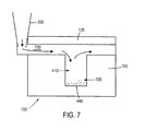
- Figure 7 shows an exemplary arrangement of how cells can be effectively captured using a device 100 such as that described heretofore.
- a fluid 700 having a culture medium with cells of interest entrained therein is provided in a sample pipette 300. Volumes of the order of 1 to 400 microlitres may be provided in the pipette.
- the fluid will be gravity fed in that it will enter downwardly into the device under the effect of gravity. On introduction its direction of flow is substantially parallel to the surface of the substrate prior to encountering the capture chamber or trench. In this region the fluid will pass downwardly and slow down- per Figure 6 .
- Any cell matter 705 within the fluid will displace from the fluid and settle on the bottom 440 of the trench under the impact of a sedimentation force with a substantial component in the direction of the capture chamber. This cell matter can be tested in any one of a number of different arrangements.
- the device heretofore described has application in any analysis technique that requires capture of cellular or other particulate matter, in that it provides for an effective capture of the cellular matter from a fluid medium in which it is conveyed, it will be further appreciated that such a capture region provides an effective experimental region wherein a capture cell can be stimulated or modified by suitable experimental techniques.
- a capture cell can be stimulated or modified by suitable experimental techniques.
- NASBA analysis which it will be appreciated is a specific example of nucleic acid amplification.
- NASBA Nucleic Acid Sequence-Based Amplification
- PCR polymerase chain reaction
- SDA strand-displacement amplification
- RCA rolling-circle amplification
- NASBA has the unique characteristic that it can, in a single step, amplify RNA sequences.
- PCR polymerase chain reaction
- SDA strand-displacement amplification
- RCA rolling-circle amplification
- NASBA has the unique characteristic that it can, in a single step, amplify RNA sequences.
- avian myeloblastosis virus reverse transcriptase, RNase H, and T7 RNA polymerase avian myeloblastosis virus reverse transcriptase
- nucleic acid types including mRNA, rRNA, tmRNA, and ssDNA, as well as nucleic acids from virus particles, can be analysed with NASBA, enabling a range of diagnostics, along with gene expression and cell viability measurements.
- the one step NASBA protocol can achieve levels of detection of extracted RNA a hundred times lower compared to the three step RT-PCR protocol.
- NASBA has the unique ability to specifically amplify RNA in a background of DNA of a comparable sequence, this reduces the sample purification requirements.
- a device such as that provided in accordance with the present teaching has specific application in NASBA analysis or indeed in other techniques that require the sequential delivery of multiple fluids.
- Each microfluidic device 100 or CCPE element module can be configured to capture cells from a fluid passing within the device flow, long term culture them, stimulate them with drugs and agonists, stain them, lyse them and finally perform real-time NASBA analysis and/or an immuno assay analysis all within the same chamber.
- An example of such a methodology will be described with reference to Figure 8 .
- Step 800 a culture medium 700 is introduced into the device. This may be done in one or more repeated steps and during this cell culture phase the entire device is placed in a standard cell culture incubator where, if required, conditions such as concentration of C0 2 can be controlled. The presence of the culture medium and the controlled ambient conditions allow for a culturing of the cells captured within the trench. Once these have been cultured, it is then possible to change the fluid within the device.
- a lysis mixture 700A is introduced into the device.
- the lysis mixture once introduced can be left in-situ within the device (Step 820) for a sufficient period of time to allow for cell lysis.
- the flow through fluid can be changed again such that for example NASBA reagents 700B may be introduced into the device (Step 830).
- Analysis of the reaction of the lysate mixture 850 to the introduced NASBA reagents can be assessed in real time.
- the device may be mounted on a standard automated temperature controlled fluorescence microscope stage and the change in fluorescence from each trench may be measured as a function of time.
- the device is designed in such a way that the fluidic resistivity of all the inlets is equal and low enough so that the pressure generated by a standard pipette is sufficient to drive fluids into the device.
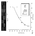
- Figure 9 shows exemplary results achieved from a multiplexed array structure such as that shown in Figure 2 .
- the signal responses 900 for each of the individual devices are evident.
- the array 910 eight individual responses are evident.
- Each response is reflective of the reaction that has occurred within an individual capture chamber.
- the injection flow rate has an effect on cell and particulate matter loading within the trench or capture region. Cells or particles suspended in a fluid are flown into the device, and as long as the injection flow rate is below a certain threshold all cells that pass over the cavity region will sediment and be trapped within the cavity.
- Figure 11 illustrates a scenario where HeLa cells 1105 are trapped within several trenches 1100A, 1100B, 1100C, 1100D.
- Each of the four trenches has identical dimensions 100x400 ⁇ m with a depth of 320 ⁇ m, while the flow path had a height of 40 ⁇ m.
- the injection flow rate was 50 nL/min.
- the HeLA 1105 cells are trapped within the chambers. Further statistical analysis on additional chambers as shown in Figure 12 shows cell loading relative standard deviation of 7.8%.
- Figure 13 shows a modification where 1.5 ⁇ m silica beads were captured within the cavity; the reference numerals used are the same as what was used for Figure 4 . After 30 min of loading the beads have begun to fill the cavity and almost no beads were detected escaping the cavity. The same experimental conditions were employed for the arrangement of Figure 11 as for Figure 13 . The injection flow rate was 50 nL/min in the direction of the arrow 1301. Statistical measurements have shown 99.75% capture efficiency.
- the fluid volume within the trench can be easily replaced with a new solution by just flowing the new solution over the cavity.
- a fluorescent dye solution was introduced into a device having previously received water, the water being retained within a 300 micron deep trench. The flow rate was approx. 500 ⁇ m/s. Within 5 min the dye solution had completely replaced the pure water.
- step 1 the cells 705 were loaded and cultured by introduction of a culture medium 700.
- Step 2 shows the provision of a layer of pre-coated RNA capture beads 1600 on top of the cells 705.
- a lysis mixture 700A is introduced in Step 3. This effects a break down of the cell walls and generates a lysate mixture 1605.
- the lysate mixture mixes with the beads and after about 30 minutes incubation the beads capture the cell RNA.
- the remains may be washed away by flowing through another volume of liquid such as PBS 1610.
- test may be conducted on cells that are constrained within the capture region.
- immuno-assay and real time NASBA analysis can then be performed by following the steps shown in Figure 18 .
- the device is mounted on a standard automated temperature controlled fluorescence microscope stage and the change in fluorescence from each capture region is measured as a function of time ( Figure 19 & 20 ).
- Steps 1 through 4 are the same as what was described with reference to Figure 16 .
- Step 5 a fluorescently labelled antibody mixture 1800 was introduced into the device. Unbound fluorescent anti-bodies may be washed away with PBS 1610 or other suitable washing or dilution materials, and the fluorescence measured. It will be appreciated that a complete washing may not be required in that the sequential flow of the additional fluid may simply effect a dilution of the previously entrained fluid within the chamber.
- Step 6 Any fluorescence around an antibody coated bead is due to protein in the target. This fluorescence may be optically analysed.
- Step 7 a NASBA reagent mixture 1810 was introduced into the device.
- Step 8 demonstrates how real time NASBA may be done by incubating the device at 41°C and monitoring the increase in fluorescence in the capture region. Any increase in fluorescence can be attributed to generation of more amplicons and opening of molecular beacons. It will be appreciated that this sequence of steps shows how the same capture chamber 410 may be used as a receiving volume for a plurality of different fluids, each of the fluids having an effect on the cells or subsequent mixture resultant from the exposure of the cells to a previously introduced fluid.
- Figure 19 shows fluorescence images of approximately sixteen individual devices at the beginning of the NASBA reaction. The different chamber coatings are also indicated.
- Figure 20 shows simultaneous change in fluorescence within sixteen devices during the NASBA reactions. The coatings within the different capture regions was varied. Twelve positive control experiments were done, together with four negative controls within a single monolithic device.
- a device provided in accordance with the present teaching as a reaction chamber for NASBA type experiments demonstrates the useful employment of such a device for experiments that require contact between a captured cell and a sequence of fluids.
- a capture chamber or trench By retaining the cell within a capture chamber or trench and then simply flowing different fluids past that captured cell, it is possible to achieve capture, labelling and analysis within a single structure. Therefore it will be understood that while the teaching has benefit and application in NASBA that it could also be used in other applications that require exposure of a captured cell to different fluids.
- Such application to lab on a chip technology with sample-in, experiment and answer out capability will be evident to those skilled in the art.
- Use of devices such as those heretofore described have benefit in that they can enable screening and diagnostics with lower cost, less contamination, and smaller sample volumes.
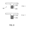
- a device 100 can be used to generate 3D cell structures 2100 of individual cancer cells 2105 so as to recreate cellular conditions similar to in-vivo tumours or other structures. This can also be combined with the fact that multiple cell types can be incorporated in a layered fashion to form co-cultures that further approximate in-vivo like conditions.
- Step 2 of Figure 21 An example of such a 3D co-culture like experimental setup for investigating cancer cell dynamics close to blood vessels 2110 (endothelial cells) is shown in Step 2 of Figure 21 .
- By selectively varying the nature of the fluid passing over the capture chamber it is possible to selectively layer the particles that are ultimately captured within the chamber. As these will typically be retained in the order that they were introduced into the chamber, this allows for subsequent experiments to be conducted within pseudo in vivo conditions.
- the arrangements described herein preferentially retain the particles within the trench it is possible to modify the arrangement so as to provide for subsequent movement of the particles - either within the trench so as to provide for mixing or the like, or to effect removal of the particles out of the trench. Such arrangements will typically require a capacity to manipulate the particles and this can be conducted either before or subsequent to capture of the particles within the trench. Examples of techniques that could be employed include:
- a further example of the use of such a capture chamber is in the analysis of E. Coli bacterial cells.
- a solution containing the E. Coli is flown into the device in a manner as described heretofore. This capture allows for cell based assays to be conducted.
- the device is loaded with the bacterial solution.
- a washing or dilution solution is flown in to rinse out any non captured bacteria. Due to the low flow field at the bottom of the processing chamber trench, the bacteria present there will be effectively captured and not washed away. Due to the very low density of the E. Coli bacteria, the capture efficiency is much lower than that of denser particles or cells such as cancer cells.
- FIG. 22 it is shown how a FITC dye (44 ⁇ M) is flown into a previously water filled device and allowed to mix with the water within the trench chamber.
- the input flow velocity is ⁇ 400 ⁇ m/sec
- an array structure such as described heretofore is flexible and can be easily integrated into existing infrastructure and workflows such as robotic pipetting systems, incubators, and fluorescent microscope systems.
- the capture chamber may be considered as a sediment trap whereby the particles within the fluid, such as for cells or other living organisms, which are entrained within the fluid on passing the capture chamber are displaced out of the fluid and remain in the capture chamber for subsequent analysis or experimentation. As they simply fall out of the fluid they are exposed to minimum shear stress. These particles will consolidate on the bottom of the capture chamber to provide what may be considered a sediment on the chamber base. As more particles are retained within the capture chamber, the height of the sediment will increase.
- a primary force providing for the delivery and/or movement of the fluid/particles within the devices
- a primary force to employ a second force which acts on the particles or the fluid flow to either supplement or counteract the effects of the first force on the fluid or particles.
- This could be employed either locally within the devices to cause specific movement of the flow/particles within specific regions of the device or could be applied as a general force to affect the overall flow/movement characteristics. Examples of such a second force which can be used to reinforce or suppress particle sedimentation / retention into the trench and / or liquid flow patterns the particle is exposed include:
- liquid sequencing within the context of devices provided in accordance with the present invention.
- Such liquid sequencing could employ one or more immiscible liquids where for example a second liquid, e.g. oil phase, seals a previously provided aqueous phase residing in trench.
- a second liquid e.g. oil phase
- a train of mutually immiscible phases to feed different reagents to trenches.
- one of the liquids in the sequence may be (another) particle suspension from which particles might differentially sediment into the trench(es).
- Devices provided in accordance with the present invention desirably provide for changes in the flow rate of the fluid passing through the device in regions proximal to the trench, the change of flow rate effecting a collection of particles from that fluid.
- different fluids may have different flow rates when exerted to the same force. This could be used as a means to preferentially collect particles from a first fluid in a first trench and particles from a second fluid in a second trench. While it is not intended to limit the teaching of present invention to any one set of specific parameters simulation analysis has shown the variations in the flow velocity magnitudes in the processing chamber and trench. Cell capture is achieved due to the flow velocity magnitude in the trench being approximately 3 orders of magnitude lower the flow above it. As a result of these variances, the particles that enter the low flow velocity region are effectively captured.
- the particles/fluid that are collected and retained in the trenches can be subjected to a number of different tests such as for example:
- a device such as that fabricated in accordance with the present teaching has a number of advantages including its application to efficient cell capture with minimal clogging and exposure of the cells to shear stress.
- the device is suitable for in situ cell culturing and can also be considered for providing 3-D cell co-culturing.
- An exemplary application has been demonstrated in multi-flow analysis techniques which may be effected without removal of the captured cells from their capture chamber.
- Such devices may be provided in single element packages or could be arranged in array structures where a plurality of devices share a common input. Further modification has been described in the context of a multiplexed structure that provides multiple capture regions within the same substrate. These devices can be implemented or fabricated using conventional microfluidic engineering principles. Use of plurality of devices provides for fluidic isolation of separate modules on a single chip. While it is not intended to limit the teaching to any one specific arrangement, the introduction of a fluid into the devices using integrated gravity driven pumping units on a monolithic micro device is particularly useful.
- FIG. 23 shows an example of such an application whereby the real time measurement of the level of surface protein expression may be effected.
- This exemplary procedure is based on the specific binding of labelled antibodies to the surface protein of interest (target proteins).
- the real-time measurement is achieved by having the surface protein within a microfluidic system that constantly refreshes a low concentration of antibodies in the medium. As new target proteins are expressed on the surface, the labelled antibodies in the medium solution specifically bind and label the proteins. The consumed anti-bodies are replaced by microfluidic refreshment so as to keep a constant supply of dissolved antibodies.
- the surface protein concentration is directly correlated to the signal from the surface labels.
- this application advantageously employs the use of the microfluidic trench structure that has been described heretofore.
- the structure has been demonstrated to be capable of very efficient cell capture and retention coupled with constant perfusion and refreshment of the soluble factors within the trench
- the present inventors have realised that the exact elements required for real time surface protein expression detection can be achieved with microfluidic systems.
- the capability of real time protein expression detection has not been previously demonstrated or reproduced in the macro-scale or with conventional equipment.
- the real time protein expression measurement was achieved by maintaining a very low concentration of fluorescently labelled antibodies in the perfusion medium.
- FITC-labelled anti-CD86 antibodies were used at concentration 1/100 of neat.
- the fluorescent antibody in this case was specific to the CD86 co-stimulatory molecule.
- macrophage cells are activated and over express co-stimulatory molecules such as CD80, CD86 and CD40 on their surface which helps induce an effective T-cell response. This is one of the key mechanisms and outcomes of activated macrophages that makes them behave as antigen presenting cells (APCs) and activates the adaptive immune system.
- APCs antigen presenting cells
- this application of the sequential flow analysis tool is based on the capabilities of the described microfluidic system to refresh dissolved agents.
- a low concentration of in-solution labelled antibodies combined with the stall micro-dimensions of microfluidic cavities, a low background signal can be maintained while always having antibodies available for labelling. This way any incubation and washing steps, usually required in conventional immunoassays become unnecessary, enabling the real time labelling and monitoring of surface proteins as they are generated.
- Figure 24 shows in schematic form how the same device may be used for RNA analysis and protein analysis; the variation being on the reagents that are introduced into the individual chambers. While the figure schematically shows the two different analysis occurring in parallel, it will be understood that this is shown purely to emphasise the application of the sequential flow analysis apparatus of the present teaching to two different analysis.
- Step 2400 a common step, cells are loaded in a similar fashion to that which was described before.
- Step 2405 these cells may be cultured and stimulated through introduction of a culture medium. The technique branches thereafter depending on whether RNA or protein analysis is desired.
- RNA analysis firstly a fixing buffer followed by a lysis buffer are introduced to fix and lysis the cells (Step 2410). After a predetermined time period a real time NASBA mixture is introduced (Step 2415). After incubation at desired temperatures (about 41 °C) a fluorescence analysis (Step 2420) will provide the RNA analysis.
- a fixing buffer is introduced to fix the cells within the chamber (Step 2425).
- Subsequent loading of an antibody buffer provides an immuno-stain (Step 2430).
- the subsequent washing of the unbound antibodies (Step 2435) and luminescent analysis of the chambers will provide information on the protein.
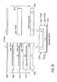
- Step 25 shows an exemplary flow sequence that may be adopted to advantageously simplify the alignment and complexity of manufacture.
- two layers of PDMS a fluidic layer and a lid/inlet layer
- a support glass substrate are employed.
- Step 2500 two different Si wafers are provided.
- a layer of SU-8 photoresist is provided (Step 2505).
- a second layer of SU-8 is then provided on the first layer to define an upstanding profile on the first layer (step 2510).
- a layer of PDMS is provided on the second wafer. This layer is then peeled and punched to generate what will ultimately form inlets to the device (Step 2520).
- a PDMS layer is provided over the SU-8 layer so as to encapsulate the layers (Step 2525).
- the SU-8 may be eroded to define a pattern within the PDMS layer (Step 2530).
- a trench and inlets are fabricated (Step 2535).
- a technique such as that described herein can be used for analysis of cell secretion where cells secrete proteins into their surrounding extracellular fluid.
- By being able to spatially discriminate the detected optical signal it is possible to analyse the nature of the origin of the optical signal.
- To provide for spatial discrimination as to the origin of the desired optical signal it is necessary to be able to discriminate between the bulk contribution to the detected signal and that signal that originates from the sample or analyte of interest.
- One way of achieving this is to effect a mathematical integral technique whereby the detected intensity of the luminescent signal originating from the top of the collection chamber down to the surface of the sample region is compared with that originating from proximal or at the surface of the sample region.
Landscapes
- Chemical & Material Sciences (AREA)
- Health & Medical Sciences (AREA)
- Chemical Kinetics & Catalysis (AREA)
- General Health & Medical Sciences (AREA)
- Clinical Laboratory Science (AREA)
- Hematology (AREA)
- Dispersion Chemistry (AREA)
- Analytical Chemistry (AREA)
- Physics & Mathematics (AREA)
- Fluid Mechanics (AREA)
- Computer Hardware Design (AREA)
- Microelectronics & Electronic Packaging (AREA)
- Engineering & Computer Science (AREA)
- Apparatus Associated With Microorganisms And Enzymes (AREA)
- Measuring Or Testing Involving Enzymes Or Micro-Organisms (AREA)
- Sampling And Sample Adjustment (AREA)
- Automatic Analysis And Handling Materials Therefor (AREA)
Claims (19)
- Vorrichtung für mehrfach-aufeinanderfolgende Strömungsproben umfassend eine mikrofluidische Einrichtung, wobei die Einrichtung umfasst:a. eine Fluidbahn (400), die innerhalb eines Substrats zwischen einem Einlass (120) und einem Auslass (130) begrenzt ist, wobei die Einrichtung eine Auffangkammer (160) umfasst, die sich innerhalb der Fluidbahn (400) befindet und sich quer zu ihr erstreckt und sie vollständig durchquert, um Partikel, die innerhalb eines Fluids strömen, selektiv aufzufangen, so dass diese Partikel die Auffangkammer (160) durchqueren müssen und aus dem Fluid verdrängt werden und in der Auffangkammer zurückbleiben, wenn das Fluid über die Auffangkammer (160) fließt, wobei die Auffangkammer (160) derart dimensioniert ist und sich in das Substrat in eine Richtung im Wesentlichen senkrecht zur Fluidbahn erstreckt, dass sich in Betrieb befindliche Partikel eines vordefinierten Ausmaßes, die sich innerhalb dem in der Fluidbahn (400) strömenden Fluid befinden, aufgrund der Einwirkung einer Gravitationskraft auf die Partikel bevorzugt innerhalb der Auffangkammer gesammelt werden, wobei die Gravitationskraft in einer Richtung wirkt, die zur Erstreckungsrichtung der Auffangkammer (160) in das Substrat im Wesentlichen parallel ist und,
wobei die Vorrichtung für aufeinanderfolgende Fluidbeaufschlagung mit einer Vielzahl von Fluideinspeiseleitungen ausgestaltet ist und die Auffangkammer (160) so ausgestaltet ist, dass Zellen, die innerhalb des Fluids aus den Fluideinspeiseleitungen mitgeschleppt werden bevorzugt aus dem Fluid verdrängt werden und in der Auffangkammer zurückbleiben. - Die Vorrichtung nach Anspruch 1, wobei die Fluidbahn der Einrichtung innerhalb des Substrats bereitgestellt wird und die Fluidbahn einen Kanal mit Boden-, Ober- und Seitenwänden ausbildet.
- Die Vorrichtung nach Anspruch 2, wobei die Fluidbahn der Einrichtung entlang einer Achse angeordnet ist, die zu einer Oberseite des Substrats im Wesentlichen parallel ist.
- Die Vorrichtung nach einem der vorangehenden Ansprüche, wobei die Fluidbahn der Einrichtung nah an einer Oberseite des Substrats ist.
- Die Vorrichtung nach einem der vorangehenden Ansprüche, wobei die Auffangkammer der Einrichtung in Form eines Grabens (440) mit einer Mündung ist, die an die Fluidbahn angrenzt und mit ihr in Fluidverbindung steht, wobei der Graben (440) Seitenwände aufweist, die sich in das Substrat aus der Mündung des Grabens im Wesentlichen parallel zur Richtung der Gravitationskraft erstrecken.
- Die Vorrichtung nach Anspruch 5, wobei der Graben (440) eine Hauptachse aufweist, die zur Fluidbahn im Wesentlichen senkrecht ist, wobei die Länge des Grabens (440) parallel zu dieser Hauptachse größer ist als seine Länge senkrecht zu dieser Hauptachse.
- Die Vorrichtung nach Anspruch 6, so ausgestaltet, dass das sich in Betrieb befindliche Fluidströmen innerhalb der Fluidbahn und das absteigende Eintreten in den Graben mit einer Verminderung der Geschwindigkeit einher geht und das Austreten des Fluids aus dem Graben mit einer Steigerung der Geschwindigkeit einher geht, wobei die Geschwindigkeitsveränderung innerhalb des Grabens dazu führt, dass die Partikel innerhalb des Fluids aus dem Fluid verdrängt werden.
- Die Vorrichtung nach einem der vorangehenden Ansprüche, wobei die Fluideinspeiseleitung einen Filter umfasst, der sich zwischen dem Einlass und der Auffangkammer befindet, so dass sich in Betrieb befindliche Partikel eines vordefinierten Ausmaßes, die sich innerhalb dem in der Fluidbahn strömenden Fluid befinden, vor der Auffangkammer herausgefiltert werden.
- Die Vorrichtung nach einem der Ansprüche 1 bis 7, wobei die Auffangkammer so ausgestaltet ist, dass sich das Ableiten eines vorher bereitgestellten Fluids auf ein entsprechendes Ableiten der innerhalb der Auffangkammer gesammelten Partikel nicht auswirkt.
- Die Vorrichtung nach einem der vorangehenden Ansprüche, umfassenda. Mittel zum Einleiten eines ersten Fluidstroms in den Einlass der Einrichtung und hinter die Auffangkammer, wobei das Einleiten des ersten Fluids in die Einrichtung das Auffangen von Partikeln innerhalb des ersten Fluids innerhalb der Auffangkammer bewirkt;b. Mittel zum Einleiten eines zweiten Fluidstroms in den Einlass der Einrichtung und hinter die Auffangkammer im Anschluss an das Einleiten des ersten Fluids, wobei der zweite Fluidstrom hinter der Auffangkammer ein diffusives Mischen des zweiten Fluids mit dem ersten Fluid innerhalb der Auffangkammer bewirkt.
- Nukleinsäureamplifikationsgerät umfassend die Vorrichtung nach einem der vorangehenden Ansprüche.
- Verfahren zur Untersuchung von Partikeln, wobei das Verfahren umfasst:a. Bereitstellen einer mikrofluidischen Einrichtung umfassend eine Fluidbahn (400), die innerhalb eines Substrats zwischen einem Einlass (120) und einem Auslass (130) festgelegt ist, wobei die Einrichtung eine Auffangkammer (160) umfasst, die sich innerhalb der Fluidbahn (400) befindet und sich quer zu ihr erstreckt und sie vollständig durchquert, wobei sich die Auffangkammer (160) in das Substrat in eine Richtung erstreckt, die zur Fluidbahn (400) im Wesentlichen senkrecht ist, so dass sich in Betrieb befindliche Partikel, die sich innerhalb dem in der Fluidbahn (400) strömenden Fluid befinden, die Auffangkammer (400) passieren müssen, wo sie aufgrund der Einwirkung einer Gravitationskraft auf diese Partikel im Bereich der Kammer (160) innerhalb der Auffangkammer (160) gesammelt werden;b. Einleiten eines ersten Fluidstroms in die Einrichtung, wobei der Strom des Fluids hinter der Auffangkammer (160) ein Auffangen von Partikeln innerhalb der Auffangkammer (160) der Einrichtung bewirkt;c. Strömen eines Reagenzes durch die Einrichtung, wobei der Strom des Reagenzes hinter der Auffangkammer (160) eine Wechselwirkung zwischen dem Reagenz und den vorher aufgefangenen Partikeln innerhalb der Auffangkammer (160) bewirkt;d. Untersuchen der Auffangkammer (160).
- Verfahren nach Anspruch 12, wobei der Strom des Reagenzes hinter der Auffangkammer (160) ein diffusives Mischen des Reagenzes mit dem ersten Fluid innerhalb der Auffangkammer (160) bewirkt.
- Verfahren nach Anspruch 12 oder 13, wobei die Untersuchung des Auffangbereichs unter Verwendung von Fluoreszenzmessungen bewirkt wird.
- Verfahren nach einem der Ansprüche 12 bis 14, umfassend eine Behandlung der Partikel oder, wenn die Partikel Zellen sind, eine Kultivierung der innerhalb der Auffangkammer (160) gesammelten Zellen.
- Verfahren nach einem der Ansprüche 12 bis 15 zur Verwendung in der Nukleinsäureamplifikation.
- Verfahren zum Durchführen eines Immunassays und einer Nukleinsäureamplifikation, umfassend das Verfahren, das in einem der Ansprüche 12 bis 15 beansprucht ist, wobei die Partikel zelluläres Material sind, wobei das Verfahren weiterhin das Kultivieren des zellulären Materials innerhalb der Auffangkammer (160) vor dem Einleiten des Reagenzes in die Einrichtung umfasst, wobei das Reagenz künstliche Kügelchen bzw. Beads umfasst und der Strom des Reagenzes das Auffangen der Beads innerhalb der Kammer bewirkt, wobei das Verfahren vor dem Untersuchungsschritt weiterhin die folgenden Schritte umfasst:a. Einleiten eines dritten Fluids in die Sammeleinrichtung, wobei das dritte Fluid ein Lysieren des zellulären Materials bewirkt;b. Einleiten eines vierten Fluids in die Sammeleinrichtung, wobei das vierte Fluid eine Verdünnung der zellulären Bruchstücke bewirkt;c. Einleiten eines fünften Fluids in die Sammeleinrichtung, wobei das fünfte Fluid eine Immunfluoreszenzfärbung des Materials innerhalb der Sammeleinrichtung bewirkt;d. Einleiten eines sechsten Fluids in die Sammeleinrichtung, wobei das sechste Fluid eine Verdünnung der ungebundenen Fluorophore bewirkt;e. Untersuchen der Reaktion der Beads innerhalb der Sammeleinrichtung (160);f. Einleiten eines siebten Fluids in die Sammeleinrichtung, wobei das siebte Fluid Nukleinsäureamplifikationsreagenzien und/oder fluoreszierende Sonden umfasst;
und wobei der finale Untersuchungsschritt die Untersuchung der Antwort der Inhalte auf die eingeleiteten Nukleinsäureamplifikationsreagenzien innerhalb der Auffangkammer umfasst. - Verfahren zum Durchführen einer Proteinuntersuchung umfassend das Verfahren, das in einem der Ansprüche 12 bis 15 beansprucht ist, wobei die Partikel zelluläres Material sind, wobei das Verfahren weiterhin das Kultivieren des zellulären Materials innerhalb der Auffangkammer (160) vor dem Einleiten des Reagenz in die Einrichtung umfasst, wobei das Reagenz einen Fixierpuffer umfasst, wobei der Strom des Reagenz ein Fixieren des zellulären Materials innerhalb der Kammer bewirkt, wobei das Verfahren vor dem Untersuchungsschritt die folgenden Schritte umfasst:Einleiten eines Antikörperpuffers in die Auffangkammer (160), wobei der Antikörperpuffer ein Anfärben des zellulären Materials bewirkt;Einleiten eines vierten Fluids in die Auffangkammer (160), wobei das vierte Fluid eine Verdünnung der ungebundenen Antikörper bewirkt;und wobei der Untersuchungsschritt die Untersuchung der lumineszierenden Antwort der Inhalte der Auffangkammer (160) umfasst.
- Verfahren zum Durchführen einer Untersuchung des zellulären oder partikulären Materials umfassend das Verfahren nach einem der Ansprüche 12 bis 15, wobei die Partikel zelluläres Material umfassen und das Verfahren weiterhin die optische Untersuchung des innerhalb der Kammer gesammelten zellulären Materials oder partikulären Materials umfasst und, wobei die Auffangkammer (160) so ausgestaltet ist, dass das innerhalb der Kammer (160) gesammelte zelluläre oder partikuläre Material eine optische Antwort bewirkt, die von einer optischen Antwort der anderen Inhalte der Kammer (160) unterschieden werden kann.
Applications Claiming Priority (2)
| Application Number | Priority Date | Filing Date | Title |
|---|---|---|---|
| GB0818579A GB2464300A (en) | 2008-10-10 | 2008-10-10 | Microfluidic multiplexed cellular and molecular analysis device and method |
| PCT/EP2009/063229 WO2010040851A2 (en) | 2008-10-10 | 2009-10-09 | Microfluidic multiplexed cellular and molecular analysis device and method |
Publications (2)
| Publication Number | Publication Date |
|---|---|
| EP2352590A2 EP2352590A2 (de) | 2011-08-10 |
| EP2352590B1 true EP2352590B1 (de) | 2013-08-14 |
Family
ID=40083807
Family Applications (1)
| Application Number | Title | Priority Date | Filing Date |
|---|---|---|---|
| EP09783921.1A Not-in-force EP2352590B1 (de) | 2008-10-10 | 2009-10-09 | Mikrofluidische multiplexierte zellen- und molekülanalysevorrichtung und entsprechendes verfahren |
Country Status (5)
| Country | Link |
|---|---|
| US (1) | US8906669B2 (de) |
| EP (1) | EP2352590B1 (de) |
| CN (1) | CN102215966A (de) |
| GB (1) | GB2464300A (de) |
| WO (1) | WO2010040851A2 (de) |
Cited By (1)
| Publication number | Priority date | Publication date | Assignee | Title |
|---|---|---|---|---|
| WO2016015701A1 (de) | 2014-07-31 | 2016-02-04 | Schebo Biotech Ag | Vorrichtung zur bioanalytik, deren herstellung und verfahren zum nachweis von bioanalyten mittels der vorrichtung |
Families Citing this family (60)
| Publication number | Priority date | Publication date | Assignee | Title |
|---|---|---|---|---|
| US20130115606A1 (en) | 2010-07-07 | 2013-05-09 | The University Of British Columbia | System and method for microfluidic cell culture |
| US10087408B2 (en) * | 2010-07-07 | 2018-10-02 | The University Of British Columbia | System and method for microfluidic cell culture |
| US9188593B2 (en) | 2010-07-16 | 2015-11-17 | The University Of British Columbia | Methods for assaying cellular binding interactions |
| EP2684605A1 (de) | 2012-07-11 | 2014-01-15 | Biocartis SA | Verfahren zum Einspritzen von Mikropartikeln in einem Mikrofluidikkanal |
| US9857333B2 (en) | 2012-10-31 | 2018-01-02 | Berkeley Lights, Inc. | Pens for biological micro-objects |
| US11493428B2 (en) * | 2013-03-15 | 2022-11-08 | Gpb Scientific, Inc. | On-chip microfluidic processing of particles |
| KR102257305B1 (ko) | 2013-03-28 | 2021-05-28 | 더 유니버시티 오브 브리티쉬 콜롬비아 | 미세유동 장치 및 분비물의 다세포 검정법에서의 그의 사용 방법 |
| CN105849561B (zh) * | 2013-10-22 | 2018-09-14 | 伯克利之光生命科技公司 | 用于测定生物活性的微流体装置 |
| US9889445B2 (en) | 2013-10-22 | 2018-02-13 | Berkeley Lights, Inc. | Micro-fluidic devices for assaying biological activity |
| DK3060926T3 (en) * | 2013-10-22 | 2019-03-25 | Berkeley Lights Inc | EXPORTING A SELECTED GROUP OF MICROBOOKS FROM A MICROFLUID DEVICE |
| DK3060912T3 (da) * | 2013-10-22 | 2020-09-28 | Berkeley Lights Inc | Fremgangsmåde og mikrofluidanordning til analyse af biologisk aktivitet |
| EP3760703A1 (de) | 2013-10-22 | 2021-01-06 | Berkeley Lights, Inc. | Mikrofluidische vorrichtungen mit isolationsstiften sowie verfahren zum testen biologischer mikroobjekte damit |
| DK3060645T3 (en) * | 2013-10-22 | 2019-04-08 | Berkeley Lights Inc | MICROFLUID DEVICES WITH INSULATION DISEASES AND METHODS FOR TESTING BIOLOGICAL MICRO-OBJECTS |
| EP3783094B1 (de) * | 2013-10-22 | 2023-10-11 | Berkeley Lights, Inc. | Mikrofluidische vorrichtungen zum testen einer biologischen aktivität |
| US11318479B2 (en) | 2013-12-18 | 2022-05-03 | Berkeley Lights, Inc. | Capturing specific nucleic acid materials from individual biological cells in a micro-fluidic device |
| TWI509067B (zh) * | 2014-04-10 | 2015-11-21 | Nat Univ Tsing Hua | 體外細胞自動抓取共養平台系統 |
| US11192107B2 (en) | 2014-04-25 | 2021-12-07 | Berkeley Lights, Inc. | DEP force control and electrowetting control in different sections of the same microfluidic apparatus |
| WO2015188171A1 (en) | 2014-06-06 | 2015-12-10 | Berkeley Lights, Inc. | Isolating microfluidic structures and trapping bubbles |
| CN105467111A (zh) * | 2014-09-05 | 2016-04-06 | 宏达国际电子股份有限公司 | 微流道模块 |
| CN107223208B (zh) | 2014-12-09 | 2021-04-09 | 伯克利之光生命科技公司 | 微流体装置中微物体的自动检测和重新定位 |
| WO2016094715A2 (en) | 2014-12-10 | 2016-06-16 | Berkeley Lights, Inc. | Movement and selection of micro-objects in a microfluidic apparatus |
| SG11201708429WA (en) | 2015-04-22 | 2017-11-29 | Berkeley Lights Inc | Microfluidic cell culture |
| US10751715B1 (en) | 2015-04-22 | 2020-08-25 | Berkeley Lights, Inc. | Microfluidic reporter cell assay methods and kits thereof |
| CN107810059B (zh) | 2015-04-22 | 2021-03-23 | 伯克利之光生命科技公司 | 在微流体装置上冷冻和存档细胞 |
| WO2016189383A1 (en) * | 2015-05-22 | 2016-12-01 | The Hong Kong University Of Science And Technology | Droplet generator based on high aspect ratio induced droplet self-breakup |
| WO2017027838A1 (en) * | 2015-08-13 | 2017-02-16 | President And Fellows Of Harvard College | Microfluidic devices and systems for cell culture and/or assay |
| CN105032512B (zh) * | 2015-08-25 | 2017-01-04 | 辽宁中医药大学 | 用于药物配伍筛选的集成化微流控芯片、制备方法及应用 |
| US10799865B2 (en) | 2015-10-27 | 2020-10-13 | Berkeley Lights, Inc. | Microfluidic apparatus having an optimized electrowetting surface and related systems and methods |
| WO2017085032A1 (en) | 2015-11-20 | 2017-05-26 | Koninklijke Philips N.V. | Microfluidic device possessing structures enabling differential analysis of a single cell's constituents |
| CN108495712A (zh) | 2015-11-23 | 2018-09-04 | 伯克利之光生命科技公司 | 原位生成的微流体隔离结构、试剂盒及其使用方法 |
| US10705082B2 (en) | 2015-12-08 | 2020-07-07 | Berkeley Lights, Inc. | In situ-generated microfluidic assay structures, related kits, and methods of use thereof |
| CN105424922B (zh) * | 2015-12-09 | 2018-01-19 | 北京乐普医疗科技有限责任公司 | 基于磁珠包被抗体的微流控芯片及捕获心肌标志物的方法 |
| CA3009073C (en) | 2015-12-30 | 2024-11-12 | Berkeley Lights, Inc. | MICROFLUID DEVICES FOR OPTICALLY CONTROLLED CONVECTION AND MOVEMENT, KITS AND ASSOCIATED PROCESSES |
| WO2017117521A1 (en) | 2015-12-31 | 2017-07-06 | Berkeley Lights, Inc. | Tumor infilitrating cells engineered to express a pro-inflammatory polypeptide |
| EP3889176A1 (de) | 2016-01-15 | 2021-10-06 | Berkeley Lights, Inc. | Verfahren zur herstellung patientenspezifischer antikrebstherapeutika und verfahren zur behandlung davon |
| CN109922885B (zh) | 2016-03-16 | 2022-05-10 | 伯克利之光生命科技公司 | 用于基因组编辑克隆的选择和传代的方法、系统和装置 |
| EP4684881A3 (de) | 2016-04-15 | 2026-03-18 | Bruker Cellular Analysis, Inc. | Verfahren, systeme und kits für in-pen-tests |
| US10675625B2 (en) | 2016-04-15 | 2020-06-09 | Berkeley Lights, Inc | Light sequencing and patterns for dielectrophoretic transport |
| CN115678773A (zh) | 2016-05-26 | 2023-02-03 | 伯克利之光生命科技公司 | 共价修饰的表面、试剂盒及制备方法和用途 |
| CN109563539A (zh) | 2016-06-15 | 2019-04-02 | 慕尼黑路德维希马克西米利安斯大学 | 使用dna纳米技术的单分子检测或定量 |
| AU2017298545B2 (en) | 2016-07-21 | 2022-10-27 | Berkeley Lights, Inc. | Sorting of T lymphocytes in a microfluidic device |
| CA3045333A1 (en) | 2016-12-01 | 2018-06-07 | Berkeley Lights, Inc. | Automated detection and repositioning of micro-objects in microfluidic devices |
| CN110546495B (zh) | 2016-12-30 | 2022-11-01 | 加利福尼亚州立大学董事会 | 用于基因组编辑t细胞的选择和传代的方法 |
| US11426729B2 (en) * | 2017-01-24 | 2022-08-30 | The Regents Of The University Of Michigan | Systems and methods for whole cell analysis |
| WO2018183744A1 (en) | 2017-03-29 | 2018-10-04 | The Research Foundation For The State University Of New York | Microfluidic device and methods |
| EP3655158A1 (de) * | 2017-09-07 | 2020-05-27 | Sony Corporation | Partikelaufnahmekammer, partikelerfassungschip, partikelerfassungsverfahren, vorrichtung und partikelanalysesystem |
| EP3721209B1 (de) | 2017-10-15 | 2024-02-07 | Berkeley Lights, Inc. | Verfahren für in-pen-tests |
| WO2019079725A1 (en) * | 2017-10-19 | 2019-04-25 | Georgia Tech Research Corporation | MESOFLUIDIC DEVICE FOR CULTIVATION OF CELLULAR AGGREGATES |
| JP7526100B2 (ja) | 2018-05-31 | 2024-07-31 | バークレー ライツ,インコーポレイテッド | マイクロ流体デバイスによる微小物体の自動検出及び特徴付け |
| US11993766B2 (en) | 2018-09-21 | 2024-05-28 | Bruker Cellular Analysis, Inc. | Functionalized well plate, methods of preparation and use thereof |
| WO2020077274A1 (en) | 2018-10-11 | 2020-04-16 | Berkeley Lights, Inc. | Systems and methods for identification of optimized protein production and kits therefor |
| CN113366312A (zh) | 2018-11-01 | 2021-09-07 | 伯克利之光生命科技公司 | 在微流体环境中测定生物细胞的方法 |
| WO2020168258A1 (en) | 2019-02-15 | 2020-08-20 | Berkeley Lights, Inc. | Laser-assisted repositioning of a micro-object and culturing of an attachment-dependent cell in a microfluidic environment |
| WO2020223555A1 (en) | 2019-04-30 | 2020-11-05 | Berkeley Lights, Inc. | Methods for encapsulating and assaying cells |
| WO2020252488A2 (en) * | 2019-06-14 | 2020-12-17 | Akoya Biosciences, Inc. | Multiplexed tissue imaging |
| WO2022051570A1 (en) | 2020-09-07 | 2022-03-10 | Berkeley Lights, Inc. | Methods of assaying a biological cell |
| CN112742071B (zh) * | 2021-01-13 | 2022-07-05 | 西南科技大学 | 一种面向低表面能微滴定向输运与分离的结构 |
| CN114632564B (zh) * | 2022-04-20 | 2024-03-08 | 香港城市大学深圳研究院 | 一种集成微流控芯片及原代循环肿瘤细胞体外处理方法 |
| CN115627221B (zh) * | 2022-10-13 | 2025-11-04 | 中山大学 | 一种微生物快速增殖和检测装置 |
| CN115400808A (zh) * | 2022-10-31 | 2022-11-29 | 杭州跃真生物科技有限公司 | 一种微流控芯片流量精确控制装置及方法 |
Family Cites Families (10)
| Publication number | Priority date | Publication date | Assignee | Title |
|---|---|---|---|---|
| US5498392A (en) * | 1992-05-01 | 1996-03-12 | Trustees Of The University Of Pennsylvania | Mesoscale polynucleotide amplification device and method |
| US20040224300A1 (en) * | 1997-01-24 | 2004-11-11 | Shuji Terashima | Method for separating nucleated cells |
| EP0979409B1 (de) * | 1997-02-20 | 2006-12-27 | The Regents of the University of California | Plasmon-schwingteilchen, methode und vorrichtung |
| CA2408616C (en) * | 2000-05-12 | 2007-10-02 | The Board Of Trustees Of The University Of Illinois | Microfluidic channel embryo and/or oocyte handling, analysis and biological evaluation |
| WO2001087487A2 (en) * | 2000-05-15 | 2001-11-22 | Tecan Trading Ag | Bidirectional flow centrifugal microfluidic devices |
| WO2002081934A2 (en) * | 2001-04-03 | 2002-10-17 | Micronics, Inc. | Pneumatic valve interface for use in microfluidic structures |
| EP1438385A1 (de) * | 2001-10-25 | 2004-07-21 | Bar-Ilan University | Interaktiver transparenter biochip-prozessor für einzeln adressierbare zellen |
| FR2880305B1 (fr) | 2005-01-06 | 2011-06-17 | Heuliez | Toit rigide pliable a commande simplifiee |
| GB0508983D0 (en) * | 2005-05-03 | 2005-06-08 | Oxford Gene Tech Ip Ltd | Cell analyser |
| KR100843339B1 (ko) * | 2006-12-07 | 2008-07-03 | 한국전자통신연구원 | 혈액 중의 혈장 분리를 위하여 마이크로채널을 이용한혈장분리기 및 이에 의한 혈장분리방법 |
-
2008
- 2008-10-10 GB GB0818579A patent/GB2464300A/en not_active Withdrawn
-
2009
- 2009-10-09 WO PCT/EP2009/063229 patent/WO2010040851A2/en not_active Ceased
- 2009-10-09 EP EP09783921.1A patent/EP2352590B1/de not_active Not-in-force
- 2009-10-09 CN CN200980145232.3A patent/CN102215966A/zh active Pending
- 2009-10-09 US US13/123,491 patent/US8906669B2/en active Active
Cited By (1)
| Publication number | Priority date | Publication date | Assignee | Title |
|---|---|---|---|---|
| WO2016015701A1 (de) | 2014-07-31 | 2016-02-04 | Schebo Biotech Ag | Vorrichtung zur bioanalytik, deren herstellung und verfahren zum nachweis von bioanalyten mittels der vorrichtung |
Also Published As
| Publication number | Publication date |
|---|---|
| CN102215966A (zh) | 2011-10-12 |
| WO2010040851A3 (en) | 2010-06-24 |
| GB0818579D0 (en) | 2008-11-19 |
| EP2352590A2 (de) | 2011-08-10 |
| US8906669B2 (en) | 2014-12-09 |
| GB2464300A (en) | 2010-04-14 |
| WO2010040851A2 (en) | 2010-04-15 |
| US20110262906A1 (en) | 2011-10-27 |
Similar Documents
| Publication | Publication Date | Title |
|---|---|---|
| EP2352590B1 (de) | Mikrofluidische multiplexierte zellen- und molekülanalysevorrichtung und entsprechendes verfahren | |
| Gielen et al. | A fully unsupervised compartment-on-demand platform for precise nanoliter assays of time-dependent steady-state enzyme kinetics and inhibition | |
| Andersson et al. | Microfluidic devices for cellomics: a review | |
| Lindström et al. | Overview of single-cell analyses: microdevices and applications | |
| US20180272295A1 (en) | Microfluidic devices | |
| US20220041967A1 (en) | Real-time monitoring of single cell or events | |
| US20110137018A1 (en) | Magnetic separation system with pre and post processing modules | |
| Schneider et al. | Self-digitization of samples into a high-density microfluidic bottom-well array | |
| WO2010142954A1 (en) | Picowell capture devices for analysing single cells or other particles | |
| US11814671B2 (en) | System and method for leakage control in a particle capture system | |
| NO317958B1 (no) | Et mikrostromningssystem for partikkelseparasjon og analyse | |
| Khan et al. | Microfluidic devices in the fast‐growing domain of single‐cell analysis | |
| US20170216838A1 (en) | Microfluidic device with channel plates | |
| US10919036B2 (en) | Flow cells utilizing surface-attached structures, and related systems and methods | |
| Ning et al. | Recent developments of droplets-based microfluidics for bacterial analysis | |
| Huang et al. | Programmable droplet microfluidics for complex multistep bioassays | |
| CN101548004A (zh) | 用于诊断学和细胞分析的微流体方法 | |
| WO2013021035A1 (en) | Microfluids for cell-based assays | |
| Bahnemann et al. | Special Laboratory Reactors: Lab-on-a-Chip | |
| Dimov et al. | Lab-in-a-trench platform for real-time monitoring of cell surface protein expression | |
| Wilhelm et al. | Conference 9320: Microfluidics, BioMEMS, and Medical Microsystems XIII |
Legal Events
| Date | Code | Title | Description |
|---|---|---|---|
| PUAI | Public reference made under article 153(3) epc to a published international application that has entered the european phase |
Free format text: ORIGINAL CODE: 0009012 |
|
| 17P | Request for examination filed |
Effective date: 20110504 |
|
| AK | Designated contracting states |
Kind code of ref document: A2 Designated state(s): AT BE BG CH CY CZ DE DK EE ES FI FR GB GR HR HU IE IS IT LI LT LU LV MC MK MT NL NO PL PT RO SE SI SK SM TR |
|
| DAX | Request for extension of the european patent (deleted) | ||
| 17Q | First examination report despatched |
Effective date: 20120521 |
|
| GRAP | Despatch of communication of intention to grant a patent |
Free format text: ORIGINAL CODE: EPIDOSNIGR1 |
|
| GRAS | Grant fee paid |
Free format text: ORIGINAL CODE: EPIDOSNIGR3 |
|
| GRAA | (expected) grant |
Free format text: ORIGINAL CODE: 0009210 |
|
| AK | Designated contracting states |
Kind code of ref document: B1 Designated state(s): AT BE BG CH CY CZ DE DK EE ES FI FR GB GR HR HU IE IS IT LI LT LU LV MC MK MT NL NO PL PT RO SE SI SK SM TR |
|
| REG | Reference to a national code |
Ref country code: GB Ref legal event code: FG4D |
|
| REG | Reference to a national code |
Ref country code: AT Ref legal event code: REF Ref document number: 626467 Country of ref document: AT Kind code of ref document: T Effective date: 20130815 Ref country code: CH Ref legal event code: EP |
|
| REG | Reference to a national code |
Ref country code: IE Ref legal event code: FG4D |
|
| REG | Reference to a national code |
Ref country code: DE Ref legal event code: R096 Ref document number: 602009018056 Country of ref document: DE Effective date: 20131010 |
|
| REG | Reference to a national code |
Ref country code: AT Ref legal event code: MK05 Ref document number: 626467 Country of ref document: AT Kind code of ref document: T Effective date: 20130814 Ref country code: NL Ref legal event code: VDEP Effective date: 20130814 |
|
| REG | Reference to a national code |
Ref country code: LT Ref legal event code: MG4D |
|
| PG25 | Lapsed in a contracting state [announced via postgrant information from national office to epo] |
Ref country code: NO Free format text: LAPSE BECAUSE OF FAILURE TO SUBMIT A TRANSLATION OF THE DESCRIPTION OR TO PAY THE FEE WITHIN THE PRESCRIBED TIME-LIMIT Effective date: 20131114 Ref country code: IS Free format text: LAPSE BECAUSE OF FAILURE TO SUBMIT A TRANSLATION OF THE DESCRIPTION OR TO PAY THE FEE WITHIN THE PRESCRIBED TIME-LIMIT Effective date: 20131214 Ref country code: CY Free format text: LAPSE BECAUSE OF FAILURE TO SUBMIT A TRANSLATION OF THE DESCRIPTION OR TO PAY THE FEE WITHIN THE PRESCRIBED TIME-LIMIT Effective date: 20130626 Ref country code: AT Free format text: LAPSE BECAUSE OF FAILURE TO SUBMIT A TRANSLATION OF THE DESCRIPTION OR TO PAY THE FEE WITHIN THE PRESCRIBED TIME-LIMIT Effective date: 20130814 Ref country code: PT Free format text: LAPSE BECAUSE OF FAILURE TO SUBMIT A TRANSLATION OF THE DESCRIPTION OR TO PAY THE FEE WITHIN THE PRESCRIBED TIME-LIMIT Effective date: 20131216 Ref country code: SE Free format text: LAPSE BECAUSE OF FAILURE TO SUBMIT A TRANSLATION OF THE DESCRIPTION OR TO PAY THE FEE WITHIN THE PRESCRIBED TIME-LIMIT Effective date: 20130814 Ref country code: LT Free format text: LAPSE BECAUSE OF FAILURE TO SUBMIT A TRANSLATION OF THE DESCRIPTION OR TO PAY THE FEE WITHIN THE PRESCRIBED TIME-LIMIT Effective date: 20130814 Ref country code: HR Free format text: LAPSE BECAUSE OF FAILURE TO SUBMIT A TRANSLATION OF THE DESCRIPTION OR TO PAY THE FEE WITHIN THE PRESCRIBED TIME-LIMIT Effective date: 20130814 |
|
| PG25 | Lapsed in a contracting state [announced via postgrant information from national office to epo] |
Ref country code: SI Free format text: LAPSE BECAUSE OF FAILURE TO SUBMIT A TRANSLATION OF THE DESCRIPTION OR TO PAY THE FEE WITHIN THE PRESCRIBED TIME-LIMIT Effective date: 20130814 Ref country code: LV Free format text: LAPSE BECAUSE OF FAILURE TO SUBMIT A TRANSLATION OF THE DESCRIPTION OR TO PAY THE FEE WITHIN THE PRESCRIBED TIME-LIMIT Effective date: 20130814 Ref country code: FI Free format text: LAPSE BECAUSE OF FAILURE TO SUBMIT A TRANSLATION OF THE DESCRIPTION OR TO PAY THE FEE WITHIN THE PRESCRIBED TIME-LIMIT Effective date: 20130814 Ref country code: BE Free format text: LAPSE BECAUSE OF FAILURE TO SUBMIT A TRANSLATION OF THE DESCRIPTION OR TO PAY THE FEE WITHIN THE PRESCRIBED TIME-LIMIT Effective date: 20130814 Ref country code: GR Free format text: LAPSE BECAUSE OF FAILURE TO SUBMIT A TRANSLATION OF THE DESCRIPTION OR TO PAY THE FEE WITHIN THE PRESCRIBED TIME-LIMIT Effective date: 20131115 Ref country code: PL Free format text: LAPSE BECAUSE OF FAILURE TO SUBMIT A TRANSLATION OF THE DESCRIPTION OR TO PAY THE FEE WITHIN THE PRESCRIBED TIME-LIMIT Effective date: 20130814 |
|
| PG25 | Lapsed in a contracting state [announced via postgrant information from national office to epo] |
Ref country code: CY Free format text: LAPSE BECAUSE OF FAILURE TO SUBMIT A TRANSLATION OF THE DESCRIPTION OR TO PAY THE FEE WITHIN THE PRESCRIBED TIME-LIMIT Effective date: 20130814 |
|
| PG25 | Lapsed in a contracting state [announced via postgrant information from national office to epo] |
Ref country code: DK Free format text: LAPSE BECAUSE OF FAILURE TO SUBMIT A TRANSLATION OF THE DESCRIPTION OR TO PAY THE FEE WITHIN THE PRESCRIBED TIME-LIMIT Effective date: 20130814 Ref country code: EE Free format text: LAPSE BECAUSE OF FAILURE TO SUBMIT A TRANSLATION OF THE DESCRIPTION OR TO PAY THE FEE WITHIN THE PRESCRIBED TIME-LIMIT Effective date: 20130814 Ref country code: NL Free format text: LAPSE BECAUSE OF FAILURE TO SUBMIT A TRANSLATION OF THE DESCRIPTION OR TO PAY THE FEE WITHIN THE PRESCRIBED TIME-LIMIT Effective date: 20130814 Ref country code: RO Free format text: LAPSE BECAUSE OF FAILURE TO SUBMIT A TRANSLATION OF THE DESCRIPTION OR TO PAY THE FEE WITHIN THE PRESCRIBED TIME-LIMIT Effective date: 20130814 Ref country code: CZ Free format text: LAPSE BECAUSE OF FAILURE TO SUBMIT A TRANSLATION OF THE DESCRIPTION OR TO PAY THE FEE WITHIN THE PRESCRIBED TIME-LIMIT Effective date: 20130814 Ref country code: SK Free format text: LAPSE BECAUSE OF FAILURE TO SUBMIT A TRANSLATION OF THE DESCRIPTION OR TO PAY THE FEE WITHIN THE PRESCRIBED TIME-LIMIT Effective date: 20130814 |
|
| PG25 | Lapsed in a contracting state [announced via postgrant information from national office to epo] |
Ref country code: MC Free format text: LAPSE BECAUSE OF FAILURE TO SUBMIT A TRANSLATION OF THE DESCRIPTION OR TO PAY THE FEE WITHIN THE PRESCRIBED TIME-LIMIT Effective date: 20130814 Ref country code: IT Free format text: LAPSE BECAUSE OF FAILURE TO SUBMIT A TRANSLATION OF THE DESCRIPTION OR TO PAY THE FEE WITHIN THE PRESCRIBED TIME-LIMIT Effective date: 20130814 Ref country code: ES Free format text: LAPSE BECAUSE OF FAILURE TO SUBMIT A TRANSLATION OF THE DESCRIPTION OR TO PAY THE FEE WITHIN THE PRESCRIBED TIME-LIMIT Effective date: 20130814 |
|
| REG | Reference to a national code |
Ref country code: CH Ref legal event code: PL |
|
| PLBE | No opposition filed within time limit |
Free format text: ORIGINAL CODE: 0009261 |
|
| STAA | Information on the status of an ep patent application or granted ep patent |
Free format text: STATUS: NO OPPOSITION FILED WITHIN TIME LIMIT |
|
| 26N | No opposition filed |
Effective date: 20140515 |
|
| REG | Reference to a national code |
Ref country code: IE Ref legal event code: MM4A |
|
| PG25 | Lapsed in a contracting state [announced via postgrant information from national office to epo] |
Ref country code: CH Free format text: LAPSE BECAUSE OF NON-PAYMENT OF DUE FEES Effective date: 20131031 Ref country code: LI Free format text: LAPSE BECAUSE OF NON-PAYMENT OF DUE FEES Effective date: 20131031 |
|
| REG | Reference to a national code |
Ref country code: DE Ref legal event code: R097 Ref document number: 602009018056 Country of ref document: DE Effective date: 20140515 |
|
| PG25 | Lapsed in a contracting state [announced via postgrant information from national office to epo] |
Ref country code: IE Free format text: LAPSE BECAUSE OF NON-PAYMENT OF DUE FEES Effective date: 20131009 |
|
| PG25 | Lapsed in a contracting state [announced via postgrant information from national office to epo] |
Ref country code: SM Free format text: LAPSE BECAUSE OF FAILURE TO SUBMIT A TRANSLATION OF THE DESCRIPTION OR TO PAY THE FEE WITHIN THE PRESCRIBED TIME-LIMIT Effective date: 20130814 |
|
| PG25 | Lapsed in a contracting state [announced via postgrant information from national office to epo] |
Ref country code: TR Free format text: LAPSE BECAUSE OF FAILURE TO SUBMIT A TRANSLATION OF THE DESCRIPTION OR TO PAY THE FEE WITHIN THE PRESCRIBED TIME-LIMIT Effective date: 20130814 |
|
| PG25 | Lapsed in a contracting state [announced via postgrant information from national office to epo] |
Ref country code: MK Free format text: LAPSE BECAUSE OF FAILURE TO SUBMIT A TRANSLATION OF THE DESCRIPTION OR TO PAY THE FEE WITHIN THE PRESCRIBED TIME-LIMIT Effective date: 20130814 Ref country code: HU Free format text: LAPSE BECAUSE OF FAILURE TO SUBMIT A TRANSLATION OF THE DESCRIPTION OR TO PAY THE FEE WITHIN THE PRESCRIBED TIME-LIMIT; INVALID AB INITIO Effective date: 20091009 Ref country code: LU Free format text: LAPSE BECAUSE OF NON-PAYMENT OF DUE FEES Effective date: 20131009 Ref country code: BG Free format text: LAPSE BECAUSE OF FAILURE TO SUBMIT A TRANSLATION OF THE DESCRIPTION OR TO PAY THE FEE WITHIN THE PRESCRIBED TIME-LIMIT Effective date: 20130814 |
|
| PG25 | Lapsed in a contracting state [announced via postgrant information from national office to epo] |
Ref country code: MT Free format text: LAPSE BECAUSE OF FAILURE TO SUBMIT A TRANSLATION OF THE DESCRIPTION OR TO PAY THE FEE WITHIN THE PRESCRIBED TIME-LIMIT Effective date: 20130814 |
|
| REG | Reference to a national code |
Ref country code: FR Ref legal event code: PLFP Year of fee payment: 7 |
|
| REG | Reference to a national code |
Ref country code: FR Ref legal event code: PLFP Year of fee payment: 8 |
|
| REG | Reference to a national code |
Ref country code: FR Ref legal event code: PLFP Year of fee payment: 9 |
|
| REG | Reference to a national code |
Ref country code: FR Ref legal event code: PLFP Year of fee payment: 10 |
|
| PGFP | Annual fee paid to national office [announced via postgrant information from national office to epo] |
Ref country code: FR Payment date: 20201030 Year of fee payment: 12 Ref country code: DE Payment date: 20201030 Year of fee payment: 12 |
|
| REG | Reference to a national code |
Ref country code: DE Ref legal event code: R119 Ref document number: 602009018056 Country of ref document: DE |
|
| PG25 | Lapsed in a contracting state [announced via postgrant information from national office to epo] |
Ref country code: DE Free format text: LAPSE BECAUSE OF NON-PAYMENT OF DUE FEES Effective date: 20220503 |
|
| PG25 | Lapsed in a contracting state [announced via postgrant information from national office to epo] |
Ref country code: FR Free format text: LAPSE BECAUSE OF NON-PAYMENT OF DUE FEES Effective date: 20211031 |
|
| PGFP | Annual fee paid to national office [announced via postgrant information from national office to epo] |
Ref country code: GB Payment date: 20231018 Year of fee payment: 15 |
|
| GBPC | Gb: european patent ceased through non-payment of renewal fee |
Effective date: 20241009 |
|
| PG25 | Lapsed in a contracting state [announced via postgrant information from national office to epo] |
Ref country code: GB Free format text: LAPSE BECAUSE OF NON-PAYMENT OF DUE FEES Effective date: 20241009 |