EP2353451A1 - Dispositif de posture pour chaises - Google Patents
Dispositif de posture pour chaises Download PDFInfo
- Publication number
- EP2353451A1 EP2353451A1 EP11152619A EP11152619A EP2353451A1 EP 2353451 A1 EP2353451 A1 EP 2353451A1 EP 11152619 A EP11152619 A EP 11152619A EP 11152619 A EP11152619 A EP 11152619A EP 2353451 A1 EP2353451 A1 EP 2353451A1
- Authority
- EP
- European Patent Office
- Prior art keywords
- chair
- posture
- support portion
- screw
- locking
- Prior art date
- Legal status (The legal status is an assumption and is not a legal conclusion. Google has not performed a legal analysis and makes no representation as to the accuracy of the status listed.)
- Granted
Links
- 238000004873 anchoring Methods 0.000 claims abstract description 27
- 230000009471 action Effects 0.000 claims description 7
- 238000003780 insertion Methods 0.000 claims description 4
- 230000037431 insertion Effects 0.000 claims description 4
- 238000000605 extraction Methods 0.000 claims description 3
- 239000004744 fabric Substances 0.000 description 11
- 230000008878 coupling Effects 0.000 description 7
- 238000010168 coupling process Methods 0.000 description 7
- 238000005859 coupling reaction Methods 0.000 description 7
- 239000000463 material Substances 0.000 description 7
- 230000010355 oscillation Effects 0.000 description 6
- 239000004809 Teflon Substances 0.000 description 3
- 229920006362 Teflon® Polymers 0.000 description 3
- 230000008901 benefit Effects 0.000 description 3
- 238000010276 construction Methods 0.000 description 3
- 230000007246 mechanism Effects 0.000 description 2
- 230000003796 beauty Effects 0.000 description 1
- 230000000903 blocking effect Effects 0.000 description 1
- 230000002452 interceptive effect Effects 0.000 description 1
- 238000004519 manufacturing process Methods 0.000 description 1
- 238000012986 modification Methods 0.000 description 1
- 230000004048 modification Effects 0.000 description 1
- 230000000284 resting effect Effects 0.000 description 1
- 230000003068 static effect Effects 0.000 description 1
- 238000004804 winding Methods 0.000 description 1
Images



Classifications
-
- A—HUMAN NECESSITIES
- A47—FURNITURE; DOMESTIC ARTICLES OR APPLIANCES; COFFEE MILLS; SPICE MILLS; SUCTION CLEANERS IN GENERAL
- A47C—CHAIRS; SOFAS; BEDS
- A47C7/00—Parts, details, or accessories of chairs or stools
- A47C7/36—Supports for the head or the back
- A47C7/38—Supports for the head or the back for the head, e.g. detachable
- A47C7/383—Detachable or loose head- or neck-supports, e.g. horse-shoe shaped
Definitions
- the present invention concerns a posture device for chairs and a posture chair comprising such a device.
- the present invention is particularly studied to create a correct posture for make-up application, for example in film-making, photography or fashion modelling. However, this does not rule out its use on other fields as well.
- One of the general purposes of the present invention is to provide a sitting position that optimally satisfies the greatest number of the characteristics indicated above, preferably all.
- a purpose of the present invention is to provide a sitting position that is comfortable for many hours without getting in the way of the work of the professional make-up artist.
- Another general purpose of the present invention is to provide a posture device that is efficient and practical to use.
- a further purpose of the present invention is to make a posture device that is cost-effective and easy to make.
- a further purpose of the present invention is to provide a posture device that looks nice and is able to stay looking good over time.
- a further purpose of the present invention is to provide a posture device able to be coupled with pre-existing chairs.
- a further purpose of the present invention is to provide a posture chair that can easily be transported and is not very bulky.
- a further purpose of the present invention is to provide a posture chair that is easy and cost-effective to make.
- the invention concerns a posture device for chairs as defined in claim 1, in other words a posture device for chairs, characterised in that it comprises an anchoring portion to a chair and a support portion for the head and/or neck of a person sitting on the chair, the support portion for the head and/or neck comprising a movement to adjust its position with respect to the anchoring portion. Since the head of the person sitting down is the main part on which work is carried out, it is also the part that must be focussed upon for a correct positioning for work that is also comfortable.
- the adjustment movement comprises at least one rotation movement and a sliding movement that are independent from one another, i.e. such that the first can occur also without the second taking place and vice-versa.
- the adjustment movement comprises at least one rotation movement and a sliding movement that are independent from one another, i.e. such that the first can occur also without the second taking place and vice-versa.
- the rotation and sliding movement are locked or allowed through a single locking and unlocking device. This is particularly advantageous both for usefulness and for an easy construction.
- the locking and unlocking device can preferably be actuated with a single hand.
- a particularly preferred and simple example embodiment comprises a sliding guide and a rotation guide, where again for the sake of simplicity of construction and functional practicality preferably the sliding guide is guided in rotation by the rotation guide.
- the sliding guide can comprise at least one part of the rotation guide.
- the rotation guide comprises a pin and a hub rotating one with respect to the other and/or vice-versa, and the sliding guide comprises at least one portion made in a single piece with the pin or the hub.
- the locking and unlocking device preferably comprises a pair of jaws that preferably acts on the support portion for the head and/or neck with the interposition of the sliding and rotation guides.
- the jaws exert the locking action on the support portion for the head and/or neck when they are moved towards one another, or alternatively apart, the locking and unlocking device comprising a device for thrusting the jaws together or apart, preferably able to be actuated with a single hand.
- the device for thrusting the jaws comprises a screw inserted in a nut, the screw or the nut are rotated through a lever device comprising a lever with a first operative position in which it is able to rotate setting the nut or the screw in rotation and a second operative position in which it is free to rotate independently from the nut and from the screw.
- the screw can also act as rotation pin around which the support portion for the head and/or neck rotates when the locking and unlocking device is in an unlocked configuration.
- the support portion for the head and/or neck for example comprises at least one guide shaft able to slide with respect to the jaws when the locking and unlocking device is in an unlocked configuration, the at least one guide shaft having a longitudinal slot in which the screw slides.
- the screw has a portion, inserted in the longitudinal slot, with a smaller diameter than the width of said slot, and while it slides it is kept in a centred position with respect to the longitudinal slot by the sliding guide. Since the posture device is intended for use in a field where a great deal of importance is placed on beauty, this provision allows the screw not to slide on the guide shaft thus avoiding it from being ruined.
- the guide shaft can thus be made from a high-quality material or with a high-quality finish, keeping its original appearance for a long time.
- the anchoring portion in its preferred embodiments, can be coupled and decoupled with respect to a chair. This is particularly useful in the case in which the posture device is used with more than one chair, and/or with fold-up chairs, since it makes interchangeability and transportation easier. Of course, this does not rule out solutions in which the anchoring portion is removable with respect to the chair, for example in a fixed or mobile coupling, and in this last case solutions are liked in which the device, whilst being inseparable from the chair, can take up a first use position and a second transportation position.
- the anchoring portion comprises a pair of guides or anchoring elements able to be coupled with a chair
- the two guides are parallel to one another and each comprise a slot facing the slot of the other guide.
- Each guide preferably comprises a cavity for housing a chair portion.
- the cavity has two opposite ends in the direction of insertion and extraction of the chair portion, and both of the ends are open for the passage of said portion.
- one of the two ends comprises a closure element intended to go into abutment on the chair portion inserted in the cavity. This is advantageous for example to prevent undesired contact between the anchoring portion and parts of the chair, like possible armrests, which could be ruined and lose their nice appearance.
- the two guides are joined together by at least one stiffening bar of length substantially equal to the width of the back support portion of the chair with which the device is intended to couple.
- the advantage of this configuration is particularly noticeable when the support device is used together with fold-up chairs, particularly with a back support portion made from cloth, since it provide greater strength and stability.
- the two guides with a single stiffening bar intended to face a back support portion of the chair.
- the locking and unlocking device can thus be coupled with the stiffening bar on a side opposite a side intended to face the back support portion of the chair.
- the stiffening bar is concave with a concavity such that its central portion in use is the farthest from the back support portion of the chair.
- the invention concerns a posture chair according to claim 21, in other words a posture chair comprising a posture device according to the present invention.
- the invention concerns a fold-up posture chair as defined in claim 22, in other words a fold-up posture chair characterised in that it comprises a back support portion, at least partially deformable, and a posture device, comprising a support portion for the head and/or neck of a person sitting on the chair, said support portion for the head and/or neck having an adjustable position with respect to the back support portion.
- the Applicant after numerous tests, has worked out that advantageously the yielding material of the back support portion already allows correct and comfortable positioning of the back of the person sitting down if associated with the adjustment of the position of the head.
- the face is also thus correctly positioned without the need to equip the chair with further mobile parts.
- the chair is therefore simple to make and can thus be light and easy to transport, for example it is possible to keep the structure of standard fold-up chairs with a cloth seat and just add the posture device on which to rest the head, in a totally or partially removable manner from the other parts of the chair.
- the chair comprises a frame
- the posture device on which to rest the head comprises an anchoring portion to the frame of the chair and a reclinable portion with respect to the back support portion.
- the anchoring portion has an operative position in which it is anchored fixed to the frame and a non-operative position, in which it is anchored mobile or separate with respect to the frame, and in any case it preferably has an operative position in which it is anchored to the back support portion, since this reduces its size and its weight and simplifies its manufacture.
- the invention exploits standard fold-up seats in which the back support portion comprises two rigid frame portions connected by a contact portion with the back that is at least partially deformable, preferably comprising a fabric.
- the anchoring portion can be able to be coupled and decoupled with respect to the two frame portions.
- Each frame portion can for example comprise a shaft able to be inserted and extracted by sliding into/from a corresponding guide of the anchoring portion.
- the shafts of the two frame portions of standard chairs are joined together by a fabric, and the two corresponding guides preferably comprise a slot for it to pass through.
- the two guides each comprise a cavity for housing the relative shaft, the cavity having two opposite ends in the direction of insertion and extraction of the shaft. Both of the ends can be open for the passage of the shaft.
- one of the two ends can comprise a closure element, intended to go into abutment on the free end of the shaft inserted in the cavity. This prevents the guide from going into abutment on a possible armrest stripping it down or pinching the arm of the person sat down.
- the two guides can be joined together by at least one stiffening bar of length substantially equal to the width of the back support portion, and in this way the back support portion is more rigid and the chair is stronger.
- the two guides are joined by a single stiffening bar intended to be positioned, in the operative configuration, on the back of the deformable portion of the back support portion, a sufficient distance from it to prevent the contact between the two parts when a person is sitting down. This prevents the back from resting on the stiffening bar and thus stops the seat from being uncomfortable.
- the support portion for the head preferably comprises a sliding movement and an oscillation movement with respect to the anchoring portion.
- the support portion for the head is anchored onto the rear side of the at least one stiffening bar.
- a single locking and unlocking device to lock both the sliding movement and the oscillating movement of the support portion for the head with respect to the anchoring portion.
- Such a device is preferably lever-actuated, and can preferably be actuated with a single hand.
- the locking and unlocking device comprises a pair of jaws clamped together through the screwing of a screw to a nut.
- the screw or the nut are rotated through a lever device comprising a lever with a first operative position in which it is able to rotate setting the nut or the screw in rotation and a second operative position in which it is free to rotate independently from the nut and from the screw.
- a lever device comprising a lever with a first operative position in which it is able to rotate setting the nut or the screw in rotation and a second operative position in which it is free to rotate independently from the nut and from the screw.
- the screw in order to make the locking and unlocking device less bulky it is preferable for the screw to also act as a rotation pin around which the support portion for the head oscillates in the unlocked configuration.
- the support portion for the head preferably comprises a guide shaft capable of sliding between the jaws when it is in the unlocked configuration, and having a longitudinal slot in which the screw slides.
- the jaws each comprise a first portion coupled with the anchoring portion and a second portion able to rotate with respect to the first portion as a unit with the support portion for the head when the locking and unlocking device is in an unlocked configuration.
- the second rotatable portion comprises, for example, at least one rotation guide and a sliding guide for the support portion for the head, preferably made from low friction coefficient material, like teflon.
- the second portion of each jaw when it is in an unlocked configuration, advantageously rotates around the axis of the screw.
- the invention concerns a posture device for chairs, characterised in that it comprises an anchoring portion to the back support portion of a chair, such an anchoring portion comprising at least two anchoring elements arranged a predetermined distance apart, preferably substantially equivalent to the width of the back support portion of the chair, the at least two anchoring elements being joined together by a preferably concave stiffening bar.
- chair we mean a chair without a posture device according to the present invention
- posture chair we mean a chair comprising such a device
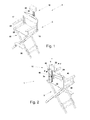
- a fold-up posture chair 1 in accordance with the present invention is shown in its open configuration to receive a person.
- the fold-up posture chair 1 comprises a chair or main support structure 5 and a posture device 10 to define the position of the head of a person sitting down.
- the main support structure 5 and the posture device 10 can be separable, partially separable or inseparable, in any case by fold-up posture chair we mean the assembly of both.
- the main support portion 5 comprises a frame 15 comprising two portions 17 and 18 joined together by a contact portion with the back 24 and by a seat 22. Both are at least partially deformable to allow passage from the open configuration of figures 1 and 2 , in which the frame portions 17 and 18 are the maximum distance apart, to a closed configuration (not illustrated) in which the frame portions 17 and 18 are the minimum distance apart or are in contact with one another, and vice-versa.
- This is made possible, in the illustrated example, by the fact that the contact portion with the back 24 and the seat 22 for example comprise a fabric or a winding of cables.
- the two frame portions 17 and 18 each comprise a rigid vertical shaft 42.
- the shafts 42 are connected together by the fabric 24 making a support portion for the back 20 that is partially deformable although with a non-reclinable frame, i.e. fixed with respect to the main structure 5 when a person is sitting down.
- the chair 1 can comprise a device on which to rest the feet 28 coupled with the frame 15.
- the posture device 10 comprises an anchoring portion 30 to the frame 15 and a support portion for the head or neck 33 of a person sat on the chair 5.
- the latter is reclinable with respect to the support portion for the back 20, and in particular it comprises an oscillation movement both in the frontward direction indicated by the arrow F and in the rearward direction indicated by the arrow P with respect to the chair 1.
- the support portion for the head 33 also comprises a vertical sliding movement according to the direction V with respect to the chair 1.
- the oscillation and sliding movements can be locked by a single locking and unlocking device 35 as will be described more clearly hereafter.
- the posture device 10 and the main support structure 5 are totally separable.
- the anchoring portion 30 comprises a pair of coupling guides 40 in which the shaft 42 of the frame 15 are slidably inserted.
- the coupling guides 40 are joined together by a single stiffening bar 45 of substantially equal length to the width of the back support portion 20 and having a curved shape with the concavity facing the frontward direction F.
- the distance between bar 45 and fabric 24 is at its maximum at the centre of the bar so that their contact is avoided, or limited, even when the fabric 24 is deformed by the weight of the person sitting down.
- the locking and unlocking device 35 is positioned on the rear side 46 of the bar 45, which in use is located opposite the side facing the fabric 24.
- the support portion for the head 33 comprises a guide shaft 37, coupled in a sliding and oscillating fashion with the locking and unlocking device 35, and a cushion 38 arranged at an end of the guide shaft 37.
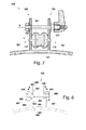
- a coupling guide 40 can be seen in detail, in particular it can be seen that it defines a cavity 50 for housing the relative shaft 42 (not shown).
- the cavity 50 has two opposite ends 52 and 53, one being open for the passage of the shaft 42 and the other being obstructed by a closure element 55 intended to go into abutment on the free end of the shaft 42 inserted into the cavity.
- a slot 58 connects together the two ends 52 and 53 to allow the passage of the fabric 24 (not shown) pulled tight between the shafts 42.
- a view from below of a guide 40 is shown where it is highlighted that the slot 58 has a width L1 that is smaller than the width L2 of the cavity 50 behind it, being defined by two tabs 60 that prevent the shafts 42 from coming out at the side.
- the locking and unlocking device 35 is shown in section.
- it comprises a pair of jaws 65 projecting in the backward direction P from the stiffening bar 45 and clamped together, in the direction of the arrows G, through a thrusting device 43 comprising a screw 67, a nut 68 and a lever device 86 to screw the screw 67 into the nut 68.
- the guide shaft 37 is inserted between the jaws 65 and is able to slide and oscillate with respect to them when they are in an unclamped configuration, or else it is locked when the jaws 65 are in a clamped configuration.
- each jaw 65 comprises a first elastic portion 70, preferably metallic, on which the clamping force exerted by the screw 67 and by the nut 68 acts directly.
- each jaw comprises a sliding guide 72, preferably made from teflon or another low friction coefficient material, arranged between the elastic portion 70 and the guide shaft 37.
- the sliding guide 72 preferably, is U-shaped so as to allow the guide shaft 37 to slide just in a predetermined direction, as will be explained hereafter.
- each jaw 65 comprises a rotation guide 74, arranged between the elastic portion 67 and the guide shaft 37.
- a rotation guide 74 arranged between the elastic portion 67 and the guide shaft 37.
- the rotation guide 74 comprises a pin 77 and a hub 74a.
- the hub 74a can be in the form of a disc of teflon or another low friction coefficient material rotatably coupled with the sliding guide 72 and/or with the elastic portion 70.
- the rotation guide 74 can comprise a hub 74a able to rotate around a pin consisting of the central portion 77 of the screw 67.
- the hub 74a and the sliding guide 72 it is preferably for the hub 74a and the sliding guide 72 to be in a single piece.
- the guide shaft 37 comprises a central slot 76 (also visible in fig 3 ) extending for part of its length, preferably its entire length, and in which the central portion 77 of the screw 67 slides.
- the central slot 76 has a greater width than the diameter of the central portion 77 of the screw 67, however the guide shaft 37 has a very limited clearance thanks to the sliding guide 72 that keeps the screw 67 at the centre of the central slot 76.
- the sliding guide 72 indeed, has holes 75 substantially of the same diameter as the screw portion 77 inserted in them - such portions 77 are preferably cylindrical and unthreaded so that the sliding guide 72 is guided in rotation.
- the sliding guide 72 finally is U-shaped with lateral abutments 79 that prevent the relative movement between it and the guide shaft 37, thus also carrying out the aforementioned centring with respect to the screw 67.
- the sliding guide 72 is made with a low friction coefficient material, it allows easy articulation of the guide shaft at the same time preventing the latter from becoming ruined by sliding on the screw. It is thus possible to make a guide shaft 37 with a high-quality and good-looking finish.
- the jaws 65 exert a substantially uniform pressure on the guide shaft 37 on both sides of the central slot 76 through the sliding guide 72.
- the guide shaft 37 has a rectangular section, however this does not rule out other types of section, such as a square section, a section according to another polygon, or round.
- the guide shaft 37 is made by coupling two rectilinear elements 78 a predetermined distance apart, corresponding to the width of the slot 76, one or both of the elements 78 having their end coupled with the cushion 38.
- the screw 67 comprises a first threaded end 80, coupled with the nut 68, and a second manoeuvring end 82.
- the screw completely passes through the two jaws 65 passing into aligned holes 83 of the elastic portions 70, and into the holes 75 of the sliding guides 72 and of the hubs 74a and is of a length such that its ends 80 and 82 project out from the elastic portions 70.
- the manoeuvring end 82 and the nut 68 have a greater diameter than the diameter of the holes 83, so that when the screw 67 is screwed into the nut 68 they thrust one jaw towards the other to carry out the clamping of the guide shaft 37.
- the manoeuvring end 82 comprises a head 84 shaped for a shape coupling with a clamping tool comprising a lever device 86.
- the lever device 86 comprises a lever 88 with a first operative position in which it is able to rotate setting the shaped head 84 of the screw in rotation, and a second operative position in which it is free to rotate independently from the screw 67.
- the lever 88 comprises a shaped cavity 90 suitable for engaging the shaped head 84, and also the lever possesses a movement towards and away from the centre of the screw 67 along its rotation axis X.
- lever 88 When the lever 88 is in the closest position it engages the shaped head 84, and when it is in the farthest position it is free to rotate with respect to the screw 67. Normally, a spring 92, or other elastic element, keeps the lever 88 in the operative position corresponding to the position closest to the screw 67.
- the nut 68 is preferably coupled with the jaws 65 so as not to be able to rotate with respect to them, so as to be able to carry out the clamping with a single hand acting on the lever 88.
- lever 88 can alternatively act with the same principle on the nut 68 while the screw 67 is kept fixed with respect to the jaws 65.
- FIG 7 an locking and unlocking device 135 alternative to the locking and unlocking device 35 of figure 6 is illustrated.
- the locking and unlocking device 135 differs from the previous one in that the guide shaft 137 oscillates around a different axis Y from the axis X of the screw 167. In this case, the guide shaft 137 does not need to have a slot for the sliding of the screw 167, and thus it is simpler to make.
- the sliding and oscillation guides are unified in an single element 172 for each jaw 165, each comprising a pin portion 173 inserted into a hole 183 of the elastic portion 170 according to the rotation axis Y. The remaining parts are the same as those of the locking and unlocking device 35 of figure 6 .
- the locking and unlocking device 435 inverts the direction of action of the jaws on the guide shaft with respect to the locking and unlocking device 35, indeed in this case there are two guide shafts 437 outside of the jaws 465 and the jaws are active on them with an outward thrusting action of the device instead of inwards.
- the jaws 65 of figure 6 have a clamping action towards the inside of the device 35
- the jaws 465 have a clamping action towards the outside of the device 435, i.e. according to the arrows E.
- This can be carried out for example with a screw 467 that passes through the aligned holes 483 of the jaws 465 in such a way that the ends of the screw 480 are able to slide in the central slots 476 of the shafts 437.
- the screw 467 has a thrusting head 484 arranged in abutment on the inner side 466 of one of the jaws 465, and moreover the screw 467 is inserted into a nut 468 arranged in abutment on the inner side 466 of the other jaw 465, and in this way when the screw 467 is given an unscrewing movement with respect to the nut 468 the thrusting head 484 and the nut 468 exert the thrust to open out the jaws 465.
- the screw 467 can be set in rotation by a lever-operated device like the one of the previous embodiments, or alternatively by a control wheel 488 rotating as a unit with the screw 467.
- any type of locking and unlocking device can be used as an alternative to those illustrated.
- the locking devices able to be actuated with a double-acting lever are the preferred ones since they allow the locking and unlocking device to be easily actuated even if positioned very close to the stiffening shaft 45, and consequently its bulk is less and the entire posture device is easier to transport and store.
- a fold-up posture chair 201 is shown that is an alternative to that of figure 1 because the posture device 210, instead of comprising two anchoring guides to the frame 215, is fixed to the back support portion 220 through a pintle 240a and an attachment device 240b, for example a screw or a peg, arranged at respective ends of the stiffening bar 245.
- the posture device 10 of figure 1 has an operative configuration in which it is anchored fixed to the frame 15 through the insertion of the guides 40 in the shafts 42, and a non-operative position in which it is completely separate from the frame 15, the posture device 210 is never completely separable from the frame 215, but comprises a first operative position in which it is anchored fixed to it through the screw 240b, and a non-operative position in which it is only free to rotate according to the arrow T thanks to the pintle 240a in order to be able to be positioned in a convenient position for the transportation of the closed chair.
- FIG 10 A further alternative embodiment of a fold-up posture chair 301 is illustrated in figure 10 . It differs from the chair 1 of figure 1 solely in that the guides 340 of the posture device 310 have openings at both ends of the cavity 350 so that they go into abutment on the armrests 351 instead of on the top of the shafts 342.
Landscapes
- Chairs For Special Purposes, Such As Reclining Chairs (AREA)
- Control Of Vending Devices And Auxiliary Devices For Vending Devices (AREA)
- Accommodation For Nursing Or Treatment Tables (AREA)
- Mutual Connection Of Rods And Tubes (AREA)
Applications Claiming Priority (1)
| Application Number | Priority Date | Filing Date | Title |
|---|---|---|---|
| ITRN2010A000002A IT1398192B1 (it) | 2010-02-01 | 2010-02-01 | Dispositivo posturale per sedie e sedia posturale comprendente tale dispositivo |
Publications (2)
| Publication Number | Publication Date |
|---|---|
| EP2353451A1 true EP2353451A1 (fr) | 2011-08-10 |
| EP2353451B1 EP2353451B1 (fr) | 2013-08-28 |
Family
ID=42710614
Family Applications (1)
| Application Number | Title | Priority Date | Filing Date |
|---|---|---|---|
| EP20110152619 Not-in-force EP2353451B1 (fr) | 2010-02-01 | 2011-01-28 | Dispositif de posture pour chaises |
Country Status (3)
| Country | Link |
|---|---|
| EP (1) | EP2353451B1 (fr) |
| ES (1) | ES2436456T3 (fr) |
| IT (1) | IT1398192B1 (fr) |
Citations (4)
| Publication number | Priority date | Publication date | Assignee | Title |
|---|---|---|---|---|
| US398893A (en) * | 1889-03-05 | Head-rest | ||
| US1576915A (en) * | 1923-03-03 | 1926-03-16 | Koenigkramer Frank | Headrest apparatus |
| US3730589A (en) * | 1971-12-09 | 1973-05-01 | Avco Corp | Head or back support for wheelchair |
| JP2006026140A (ja) * | 2004-07-16 | 2006-02-02 | Yuuki Trading:Kk | 車椅子用の後付けヘッドレスト支持機構 |
Family Cites Families (2)
| Publication number | Priority date | Publication date | Assignee | Title |
|---|---|---|---|---|
| US5690387A (en) * | 1996-10-28 | 1997-11-25 | Sarti; Ronnie A. | Removable headrest for chairs |
| US5897167A (en) * | 1997-11-20 | 1999-04-27 | Keith; Lendon V. | Detachable adjustable height headrest for a folding chair |
-
2010
- 2010-02-01 IT ITRN2010A000002A patent/IT1398192B1/it active
-
2011
- 2011-01-28 ES ES11152619T patent/ES2436456T3/es active Active
- 2011-01-28 EP EP20110152619 patent/EP2353451B1/fr not_active Not-in-force
Patent Citations (4)
| Publication number | Priority date | Publication date | Assignee | Title |
|---|---|---|---|---|
| US398893A (en) * | 1889-03-05 | Head-rest | ||
| US1576915A (en) * | 1923-03-03 | 1926-03-16 | Koenigkramer Frank | Headrest apparatus |
| US3730589A (en) * | 1971-12-09 | 1973-05-01 | Avco Corp | Head or back support for wheelchair |
| JP2006026140A (ja) * | 2004-07-16 | 2006-02-02 | Yuuki Trading:Kk | 車椅子用の後付けヘッドレスト支持機構 |
Also Published As
| Publication number | Publication date |
|---|---|
| ES2436456T3 (es) | 2014-01-02 |
| ITRN20100002A1 (it) | 2011-08-02 |
| EP2353451B1 (fr) | 2013-08-28 |
| IT1398192B1 (it) | 2013-02-14 |
Similar Documents
| Publication | Publication Date | Title |
|---|---|---|
| US20240032694A1 (en) | Portable Chair | |
| CN102946762B (zh) | 椅子 | |
| US20160100688A1 (en) | Outdoor recliner with pillow carrier | |
| TWI359643B (en) | Back support for a chair | |
| US6659563B2 (en) | Adjustable quick release frameless back support for a wheelchair | |
| US20040066075A1 (en) | Structure for adjusting backrest for collapsible chairs | |
| US8534515B2 (en) | Pivoting elastic shoulder support | |
| EP2846751B1 (fr) | Ensemble support de roue arrière de fauteuil roulant et accoudoir détachable | |
| US20170087037A1 (en) | Seat or part thereof | |
| US20070216201A1 (en) | Seating device with a foldable table | |
| KR101180482B1 (ko) | 의자 | |
| US20080122268A1 (en) | Portable seating system and method of manufacture | |
| US11330907B1 (en) | Chair with armrest connectors | |
| WO2008004583A1 (fr) | Structure de chaise inclinable | |
| EP2353451A1 (fr) | Dispositif de posture pour chaises | |
| JP7223485B2 (ja) | 座の構造、及び椅子 | |
| RU2739022C1 (ru) | Модуль сиденья | |
| US363211A (en) | William j | |
| KR102370899B1 (ko) | 휠체어 및 머리받이 | |
| JP4908826B2 (ja) | リクライニング椅子 | |
| US12588764B1 (en) | Collapsible stadium chair | |
| JP5461857B2 (ja) | 椅子 | |
| EP4482727B1 (fr) | Moyen de transport d'enfant | |
| US10820702B1 (en) | Chair seat sliding and locking mechanism | |
| KR200471916Y1 (ko) | 의자의 허리받이와 머리받이로 겸용 가능한 받침부재 |
Legal Events
| Date | Code | Title | Description |
|---|---|---|---|
| PUAI | Public reference made under article 153(3) epc to a published international application that has entered the european phase |
Free format text: ORIGINAL CODE: 0009012 |
|
| AK | Designated contracting states |
Kind code of ref document: A1 Designated state(s): AL AT BE BG CH CY CZ DE DK EE ES FI FR GB GR HR HU IE IS IT LI LT LU LV MC MK MT NL NO PL PT RO RS SE SI SK SM TR |
|
| AX | Request for extension of the european patent |
Extension state: BA ME |
|
| 17P | Request for examination filed |
Effective date: 20120207 |
|
| 17Q | First examination report despatched |
Effective date: 20120326 |
|
| GRAP | Despatch of communication of intention to grant a patent |
Free format text: ORIGINAL CODE: EPIDOSNIGR1 |
|
| INTG | Intention to grant announced |
Effective date: 20130403 |
|
| GRAS | Grant fee paid |
Free format text: ORIGINAL CODE: EPIDOSNIGR3 |
|
| GRAA | (expected) grant |
Free format text: ORIGINAL CODE: 0009210 |
|
| AK | Designated contracting states |
Kind code of ref document: B1 Designated state(s): AL AT BE BG CH CY CZ DE DK EE ES FI FR GB GR HR HU IE IS IT LI LT LU LV MC MK MT NL NO PL PT RO RS SE SI SK SM TR |
|
| REG | Reference to a national code |
Ref country code: GB Ref legal event code: FG4D |
|
| REG | Reference to a national code |
Ref country code: CH Ref legal event code: EP |
|
| REG | Reference to a national code |
Ref country code: AT Ref legal event code: REF Ref document number: 628814 Country of ref document: AT Kind code of ref document: T Effective date: 20130915 |
|
| REG | Reference to a national code |
Ref country code: IE Ref legal event code: FG4D |
|
| REG | Reference to a national code |
Ref country code: DE Ref legal event code: R096 Ref document number: 602011002747 Country of ref document: DE Effective date: 20131024 |
|
| REG | Reference to a national code |
Ref country code: ES Ref legal event code: FG2A Ref document number: 2436456 Country of ref document: ES Kind code of ref document: T3 Effective date: 20140102 |
|
| REG | Reference to a national code |
Ref country code: AT Ref legal event code: MK05 Ref document number: 628814 Country of ref document: AT Kind code of ref document: T Effective date: 20130828 |
|
| REG | Reference to a national code |
Ref country code: LT Ref legal event code: MG4D |
|
| REG | Reference to a national code |
Ref country code: NL Ref legal event code: VDEP Effective date: 20130828 |
|
| PG25 | Lapsed in a contracting state [announced via postgrant information from national office to epo] |
Ref country code: NO Free format text: LAPSE BECAUSE OF FAILURE TO SUBMIT A TRANSLATION OF THE DESCRIPTION OR TO PAY THE FEE WITHIN THE PRESCRIBED TIME-LIMIT Effective date: 20131128 Ref country code: SE Free format text: LAPSE BECAUSE OF FAILURE TO SUBMIT A TRANSLATION OF THE DESCRIPTION OR TO PAY THE FEE WITHIN THE PRESCRIBED TIME-LIMIT Effective date: 20130828 Ref country code: PT Free format text: LAPSE BECAUSE OF FAILURE TO SUBMIT A TRANSLATION OF THE DESCRIPTION OR TO PAY THE FEE WITHIN THE PRESCRIBED TIME-LIMIT Effective date: 20131230 Ref country code: AT Free format text: LAPSE BECAUSE OF FAILURE TO SUBMIT A TRANSLATION OF THE DESCRIPTION OR TO PAY THE FEE WITHIN THE PRESCRIBED TIME-LIMIT Effective date: 20130828 Ref country code: IS Free format text: LAPSE BECAUSE OF FAILURE TO SUBMIT A TRANSLATION OF THE DESCRIPTION OR TO PAY THE FEE WITHIN THE PRESCRIBED TIME-LIMIT Effective date: 20131228 Ref country code: HR Free format text: LAPSE BECAUSE OF FAILURE TO SUBMIT A TRANSLATION OF THE DESCRIPTION OR TO PAY THE FEE WITHIN THE PRESCRIBED TIME-LIMIT Effective date: 20130828 Ref country code: CY Free format text: LAPSE BECAUSE OF FAILURE TO SUBMIT A TRANSLATION OF THE DESCRIPTION OR TO PAY THE FEE WITHIN THE PRESCRIBED TIME-LIMIT Effective date: 20130626 Ref country code: LT Free format text: LAPSE BECAUSE OF FAILURE TO SUBMIT A TRANSLATION OF THE DESCRIPTION OR TO PAY THE FEE WITHIN THE PRESCRIBED TIME-LIMIT Effective date: 20130828 |
|
| REG | Reference to a national code |
Ref country code: NL Ref legal event code: VDEP Effective date: 20130828 |
|
| PG25 | Lapsed in a contracting state [announced via postgrant information from national office to epo] |
Ref country code: PL Free format text: LAPSE BECAUSE OF FAILURE TO SUBMIT A TRANSLATION OF THE DESCRIPTION OR TO PAY THE FEE WITHIN THE PRESCRIBED TIME-LIMIT Effective date: 20130828 Ref country code: GR Free format text: LAPSE BECAUSE OF FAILURE TO SUBMIT A TRANSLATION OF THE DESCRIPTION OR TO PAY THE FEE WITHIN THE PRESCRIBED TIME-LIMIT Effective date: 20131129 Ref country code: BE Free format text: LAPSE BECAUSE OF FAILURE TO SUBMIT A TRANSLATION OF THE DESCRIPTION OR TO PAY THE FEE WITHIN THE PRESCRIBED TIME-LIMIT Effective date: 20130828 Ref country code: FI Free format text: LAPSE BECAUSE OF FAILURE TO SUBMIT A TRANSLATION OF THE DESCRIPTION OR TO PAY THE FEE WITHIN THE PRESCRIBED TIME-LIMIT Effective date: 20130828 Ref country code: LV Free format text: LAPSE BECAUSE OF FAILURE TO SUBMIT A TRANSLATION OF THE DESCRIPTION OR TO PAY THE FEE WITHIN THE PRESCRIBED TIME-LIMIT Effective date: 20130828 Ref country code: SI Free format text: LAPSE BECAUSE OF FAILURE TO SUBMIT A TRANSLATION OF THE DESCRIPTION OR TO PAY THE FEE WITHIN THE PRESCRIBED TIME-LIMIT Effective date: 20130828 |
|
| PG25 | Lapsed in a contracting state [announced via postgrant information from national office to epo] |
Ref country code: CY Free format text: LAPSE BECAUSE OF FAILURE TO SUBMIT A TRANSLATION OF THE DESCRIPTION OR TO PAY THE FEE WITHIN THE PRESCRIBED TIME-LIMIT Effective date: 20130828 |
|
| PG25 | Lapsed in a contracting state [announced via postgrant information from national office to epo] |
Ref country code: NL Free format text: LAPSE BECAUSE OF FAILURE TO SUBMIT A TRANSLATION OF THE DESCRIPTION OR TO PAY THE FEE WITHIN THE PRESCRIBED TIME-LIMIT Effective date: 20130828 Ref country code: SK Free format text: LAPSE BECAUSE OF FAILURE TO SUBMIT A TRANSLATION OF THE DESCRIPTION OR TO PAY THE FEE WITHIN THE PRESCRIBED TIME-LIMIT Effective date: 20130828 Ref country code: RO Free format text: LAPSE BECAUSE OF FAILURE TO SUBMIT A TRANSLATION OF THE DESCRIPTION OR TO PAY THE FEE WITHIN THE PRESCRIBED TIME-LIMIT Effective date: 20130828 Ref country code: CZ Free format text: LAPSE BECAUSE OF FAILURE TO SUBMIT A TRANSLATION OF THE DESCRIPTION OR TO PAY THE FEE WITHIN THE PRESCRIBED TIME-LIMIT Effective date: 20130828 Ref country code: DK Free format text: LAPSE BECAUSE OF FAILURE TO SUBMIT A TRANSLATION OF THE DESCRIPTION OR TO PAY THE FEE WITHIN THE PRESCRIBED TIME-LIMIT Effective date: 20130828 Ref country code: EE Free format text: LAPSE BECAUSE OF FAILURE TO SUBMIT A TRANSLATION OF THE DESCRIPTION OR TO PAY THE FEE WITHIN THE PRESCRIBED TIME-LIMIT Effective date: 20130828 |
|
| REG | Reference to a national code |
Ref country code: DE Ref legal event code: R097 Ref document number: 602011002747 Country of ref document: DE |
|
| PLBE | No opposition filed within time limit |
Free format text: ORIGINAL CODE: 0009261 |
|
| STAA | Information on the status of an ep patent application or granted ep patent |
Free format text: STATUS: NO OPPOSITION FILED WITHIN TIME LIMIT |
|
| 26N | No opposition filed |
Effective date: 20140530 |
|
| PG25 | Lapsed in a contracting state [announced via postgrant information from national office to epo] |
Ref country code: LU Free format text: LAPSE BECAUSE OF FAILURE TO SUBMIT A TRANSLATION OF THE DESCRIPTION OR TO PAY THE FEE WITHIN THE PRESCRIBED TIME-LIMIT Effective date: 20140128 |
|
| REG | Reference to a national code |
Ref country code: DE Ref legal event code: R097 Ref document number: 602011002747 Country of ref document: DE Effective date: 20140530 |
|
| REG | Reference to a national code |
Ref country code: IE Ref legal event code: MM4A |
|
| PG25 | Lapsed in a contracting state [announced via postgrant information from national office to epo] |
Ref country code: IE Free format text: LAPSE BECAUSE OF NON-PAYMENT OF DUE FEES Effective date: 20140128 |
|
| PG25 | Lapsed in a contracting state [announced via postgrant information from national office to epo] |
Ref country code: MC Free format text: LAPSE BECAUSE OF FAILURE TO SUBMIT A TRANSLATION OF THE DESCRIPTION OR TO PAY THE FEE WITHIN THE PRESCRIBED TIME-LIMIT Effective date: 20130828 |
|
| PG25 | Lapsed in a contracting state [announced via postgrant information from national office to epo] |
Ref country code: IT Free format text: LAPSE BECAUSE OF NON-PAYMENT OF DUE FEES Effective date: 20150128 |
|
| REG | Reference to a national code |
Ref country code: FR Ref legal event code: PLFP Year of fee payment: 6 |
|
| PG25 | Lapsed in a contracting state [announced via postgrant information from national office to epo] |
Ref country code: MT Free format text: LAPSE BECAUSE OF FAILURE TO SUBMIT A TRANSLATION OF THE DESCRIPTION OR TO PAY THE FEE WITHIN THE PRESCRIBED TIME-LIMIT Effective date: 20130828 |
|
| PG25 | Lapsed in a contracting state [announced via postgrant information from national office to epo] |
Ref country code: SM Free format text: LAPSE BECAUSE OF FAILURE TO SUBMIT A TRANSLATION OF THE DESCRIPTION OR TO PAY THE FEE WITHIN THE PRESCRIBED TIME-LIMIT Effective date: 20130828 |
|
| PG25 | Lapsed in a contracting state [announced via postgrant information from national office to epo] |
Ref country code: RS Free format text: LAPSE BECAUSE OF FAILURE TO SUBMIT A TRANSLATION OF THE DESCRIPTION OR TO PAY THE FEE WITHIN THE PRESCRIBED TIME-LIMIT Effective date: 20130828 Ref country code: BG Free format text: LAPSE BECAUSE OF FAILURE TO SUBMIT A TRANSLATION OF THE DESCRIPTION OR TO PAY THE FEE WITHIN THE PRESCRIBED TIME-LIMIT Effective date: 20130828 |
|
| PG25 | Lapsed in a contracting state [announced via postgrant information from national office to epo] |
Ref country code: HU Free format text: LAPSE BECAUSE OF FAILURE TO SUBMIT A TRANSLATION OF THE DESCRIPTION OR TO PAY THE FEE WITHIN THE PRESCRIBED TIME-LIMIT; INVALID AB INITIO Effective date: 20110128 Ref country code: TR Free format text: LAPSE BECAUSE OF FAILURE TO SUBMIT A TRANSLATION OF THE DESCRIPTION OR TO PAY THE FEE WITHIN THE PRESCRIBED TIME-LIMIT Effective date: 20130828 |
|
| REG | Reference to a national code |
Ref country code: FR Ref legal event code: PLFP Year of fee payment: 7 |
|
| REG | Reference to a national code |
Ref country code: FR Ref legal event code: PLFP Year of fee payment: 8 |
|
| PG25 | Lapsed in a contracting state [announced via postgrant information from national office to epo] |
Ref country code: IT Free format text: LAPSE BECAUSE OF NON-PAYMENT OF DUE FEES Effective date: 20150128 |
|
| PGRI | Patent reinstated in contracting state [announced from national office to epo] |
Ref country code: IT Effective date: 20180104 |
|
| PGFP | Annual fee paid to national office [announced via postgrant information from national office to epo] |
Ref country code: CH Payment date: 20180118 Year of fee payment: 8 Ref country code: DE Payment date: 20180131 Year of fee payment: 8 Ref country code: ES Payment date: 20180213 Year of fee payment: 8 Ref country code: GB Payment date: 20180122 Year of fee payment: 8 |
|
| PGFP | Annual fee paid to national office [announced via postgrant information from national office to epo] |
Ref country code: IT Payment date: 20180129 Year of fee payment: 8 Ref country code: FR Payment date: 20180122 Year of fee payment: 8 |
|
| PG25 | Lapsed in a contracting state [announced via postgrant information from national office to epo] |
Ref country code: MK Free format text: LAPSE BECAUSE OF FAILURE TO SUBMIT A TRANSLATION OF THE DESCRIPTION OR TO PAY THE FEE WITHIN THE PRESCRIBED TIME-LIMIT Effective date: 20130828 |
|
| PG25 | Lapsed in a contracting state [announced via postgrant information from national office to epo] |
Ref country code: AL Free format text: LAPSE BECAUSE OF FAILURE TO SUBMIT A TRANSLATION OF THE DESCRIPTION OR TO PAY THE FEE WITHIN THE PRESCRIBED TIME-LIMIT Effective date: 20130828 |
|
| REG | Reference to a national code |
Ref country code: DE Ref legal event code: R119 Ref document number: 602011002747 Country of ref document: DE |
|
| REG | Reference to a national code |
Ref country code: CH Ref legal event code: PL |
|
| GBPC | Gb: european patent ceased through non-payment of renewal fee |
Effective date: 20190128 |
|
| PG25 | Lapsed in a contracting state [announced via postgrant information from national office to epo] |
Ref country code: FR Free format text: LAPSE BECAUSE OF NON-PAYMENT OF DUE FEES Effective date: 20190131 Ref country code: DE Free format text: LAPSE BECAUSE OF NON-PAYMENT OF DUE FEES Effective date: 20190801 |
|
| PG25 | Lapsed in a contracting state [announced via postgrant information from national office to epo] |
Ref country code: GB Free format text: LAPSE BECAUSE OF NON-PAYMENT OF DUE FEES Effective date: 20190128 Ref country code: LI Free format text: LAPSE BECAUSE OF NON-PAYMENT OF DUE FEES Effective date: 20190131 Ref country code: CH Free format text: LAPSE BECAUSE OF NON-PAYMENT OF DUE FEES Effective date: 20190131 |
|
| PG25 | Lapsed in a contracting state [announced via postgrant information from national office to epo] |
Ref country code: IT Free format text: LAPSE BECAUSE OF NON-PAYMENT OF DUE FEES Effective date: 20190128 |
|
| REG | Reference to a national code |
Ref country code: ES Ref legal event code: FD2A Effective date: 20200310 |
|
| PG25 | Lapsed in a contracting state [announced via postgrant information from national office to epo] |
Ref country code: ES Free format text: LAPSE BECAUSE OF NON-PAYMENT OF DUE FEES Effective date: 20190129 |