EP2353541A2 - Zahnmatrizenband - Google Patents
Zahnmatrizenband Download PDFInfo
- Publication number
- EP2353541A2 EP2353541A2 EP11153178A EP11153178A EP2353541A2 EP 2353541 A2 EP2353541 A2 EP 2353541A2 EP 11153178 A EP11153178 A EP 11153178A EP 11153178 A EP11153178 A EP 11153178A EP 2353541 A2 EP2353541 A2 EP 2353541A2
- Authority
- EP
- European Patent Office
- Prior art keywords
- weakness
- elongated body
- matrix band
- line
- dental matrix
- Prior art date
- Legal status (The legal status is an assumption and is not a legal conclusion. Google has not performed a legal analysis and makes no representation as to the accuracy of the status listed.)
- Withdrawn
Links
Images


Classifications
-
- A—HUMAN NECESSITIES
- A61—MEDICAL OR VETERINARY SCIENCE; HYGIENE
- A61C—DENTISTRY; APPARATUS OR METHODS FOR ORAL OR DENTAL HYGIENE
- A61C5/00—Filling or capping teeth
- A61C5/80—Dental aids fixed to teeth during treatment, e.g. tooth clamps
- A61C5/85—Filling bands, e.g. matrix bands; Manipulating tools therefor
-
- A—HUMAN NECESSITIES
- A61—MEDICAL OR VETERINARY SCIENCE; HYGIENE
- A61C—DENTISTRY; APPARATUS OR METHODS FOR ORAL OR DENTAL HYGIENE
- A61C5/00—Filling or capping teeth
- A61C5/80—Dental aids fixed to teeth during treatment, e.g. tooth clamps
- A61C5/88—Wedges
Definitions
- This application generally relates to dental products, and in particular, to dental matrix bands.
- Dental matrix bands are relatively small thin elongated strips of flexible material that are used in various dental procedures. Generally, matrix bands are used to isolate or shield the sides of adjacent teeth from one another, For example, a dental procedure where matrix bands are commonly used is the restoration of Class II dental cavities or caries.
- a tight anatomically self-contouring matrix band is preferred. This is particularly true at the interproximal, gingival and subgingival portion of the tooth to be rebuilt or restored.
- the matrix band acts as an anatomical tooth-encircling retaining wall for the filling material that replaces and restores the carious surfaces of a tooth to its original anatomy.
- the carious surfaces may be restored with silver amalgam, composites or other suitable material.
- the anatomically formed matrix band retains the shape of the restorative material until the filling material hardens, usually in minutes. Thereinafter, the matrix band is opened and removed from the tooth.
- contoured matrix bands are commonly used, they have been subject to numerous disadvantages.
- matrix bands made from overly flexible and ductile materials may present problems during placement of the matrix band, especially where the interproximal distance is smaller than the thickness of the matrix band.
- matrix bands of this type have required a tightening and retaining tool or the like to apply and hold them in position after they are placed on the tooth. Then, after completing the dental procedure, the matrix bands have to be opened with special cutting instruments, such as scissors and scalpels.
- a dental matrix band comprises an elongated body having first and second opposing ends adapted to wrap around a tooth to be restored, and having first and second opposing longitudinal edges extending between the first and second opposing ends; a first line of weakness in the elongated body intermediate the first and second opposing ends and extending substantially between the first and second opposing longitudinal edges, wherein the elongated body is separable along the first line of weakness; and a fixture adjacent the first line of weakness adapted to tear the elongated body along the first line of weakness when a sufficient force is applied to the fixture.
- a dental matrix band in another embodiment, comprises an elongated body having first and second opposing ends adapted to wrap around a tooth to be restored, and having first and second opposing longitudinal edges extending between the first and second opposing ends; a first line of weakness in the elongated body intermediate the first and second opposing ends and extending substantially between the first and second opposing longitudinal edges, wherein the elongated body is separable along the first line of weakness; a second line of weakness in the elongated body spaced apart from the first line of weakness and extending substantially between the first and second opposing longitudinal edges, wherein a removable section is formed in the elongated body between the first and second lines of weakness; a fixture adjacent the first and second lines of weakness adapted to tear the elongated body along the first and second lines of weakness to separate the removable section from the elongated body when a sufficient force is applied to the fixture; and an annealed section in the elongated body intermediate the first and second opposing ends and spaced apart from the first and second opposing
- a dental matrix band in yet another embodiment, comprises an elongated body having first and second opposing ends adapted to wrap around a tooth to be restored, and having first and second opposing longitudinal edges extending between the first and second opposing ends; and an annealed section in the elongated body intermediate the first and second opposing ends, wherein the annealed section is more ductile than a remainder of the elongated body,
- a method of performing a dental restoration comprises applying a dental matrix band to a tooth to be restored, wherein the matrix band includes an elongated body having first and second opposing ends adapted to wrap around a tooth to be restored, and having first and second opposing longitudinal edges extending between the first and second opposing ends; and a first line of weakness in the elongated body intermediate the first and second opposing ends and extending substantially between the first and second opposing longitudinal edges, wherein the elongated body is separable along the first line of weakness; and a fixture adjacent the first line of weakness adapted to tear the elongated body along the first line of weakness when a sufficient force is applied to the fixture.
- the method further comprises tightening the matrix band on the tooth with a tensioning device; applying restoration material to the tooth; applying a sufficient force on the fixture to tear the elongated body along the first line of weakness thereby severing the elongated body between the first and second opposing ends; and removing the severed matrix band from around the tooth.
- a method of performing a dental restoration comprises applying a dental matrix band to a tooth to be restored, wherein the matrix band includes an elongated body having first and second opposing ends adapted to wrap around a tooth to be restored, and having first and second opposing longitudinal edges extending between the first and second opposing ends; and an annealed section in the elongated body intermediate the first and second opposing ends, wherein the annealed section is more ductile than a remaining portion of the elongated body, The method further comprises burnishing the annealed section with a burnishing tool to adapt the annealed section to an adjacent tooth; applying restoration material to the tooth; and removing the dental matrix band from around the tooth,
- FIG. 1 is a side elevational view of a dental matrix band according to one embodiment of the invention, illustrating one line of weakness.
- FIG. 2 is a side elevational view of a dental matrix band according to another embodiment of the invention, illustrating two lines of weakness.
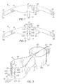
- FIG. 3 is a perspective view of the dental matrix band of FIG. 2 and a dental matrix tightener according to one embodiment of the invention.
- FIG 4 is a perspective view of the dental matrix band and tightener of FIG. 3 illustrating the matrix band placed and tightened on a tooth.
- FIG. 5 is a perspective view of the matrix band shown in FIG. 4 , following the partial tearing of the elongated body of the matrix band along the lines of weakness.
- FIG. 6 is a perspective view of the matrix band shown in FIG. 4 , showing a burnishing tool inserted into a Type II dental cavity.
- FIG. 7 is a partially-transparent perspective view of the matrix band and burnishing tool shown in FIG 6 , illustrating the burnishing of an annealed section of the dental matrix band.
- FIG. 8 is a perspective view of a dental matrix band according to one embodiment of the invention.
- FIG. 9 is a perspective view of a dental matrix band according to another embodiment of the invention.
- FIG. 1 illustrates a dental matrix band 10 according to one embodiment of the invention.
- the band 10 comprises an elongated body 12 , first and second opposing ends 14a,b and first and second opposing longitudinal edges 16a,b .
- a first line of weakness 18 in the elongated body 12 lies between the first and second opposing ends 14a,b and extends substantially between the first and second opposing longitudinal edges 16a,b .
- a fixture 24 is adjacent the first line of weakness 18 and extends from longitudinal edge 16a .
- the dental matrix band 10 may comprise a flexible material such as those commonly used within the art. Suitable materials include thermoplastics, such as polyesters, and metals, such as aluminum, titanium, iron and alloys thereof. Exemplary matrix band materials include polyethylene terephthalate (PET), aluminum, titanium, and stainless steel. Optionally, the matrix band material may further comprise a coating, such as a fluoropolymer, to impart favorable surface properties, such as reduced adhesion to the filling material.
- a coating such as a fluoropolymer
- the elongated body 12 may be in the form of a strip, wherein the opposing longitudinal edges 16a,b are approximately parallel. Alternatively, as shown in FIGS. 1-9 , the body 12 may be contoured to provide an anatomical adaptation around a tooth 42 to be restored.
- the matrix band 10 may further comprise a second line of weakness 20 that is spaced apart (i.e., separated by a distance greater than zero) from the first line of weakness 18 to form a removable section 22 within the elongated body 12 of the dental matrix band 10 .
- the fixture 24 is adjacent both the first and second lines of weakness 18, 20 and extends from longitudinal edge 16a of the removable section 22 .
- the fixture 24 may be contiguous with or attached to the removable section 22 .
- the elongated body 12 is separable along a line of weakness.
- line of weakness as used herein defines a manufactured region for an intentional failure in the elongated body 12 that will tear or separate when a sufficient force (i.e., the opening force) is applied to the fixture 24 .
- the amount of force to cause a line of weakness to fail may vary, but it is less than the adjoining regions of the elongated body 12 .
- a line of weakness is designed to fail before the adjoining regions fail and requires less force to do so.
- the opening force (F op ) is the force required to separate the elongated body 12 along a line of weakness
- the force of failure (F l ) is the force required to separate the elongated body absent any line of weakness.
- the opening force (F op ) is less than about 80% of the force of failure (F t ), for example, less than about 70% of F f , or less than about 60% of F f .
- the F op is less than about 50% of F i or less than about 25% of F i .
- the F op is about 10% to about 75% of F f , or about 20% to about 60% of F f , or about 25% to about 50% of F f .
- first line of weakness 18 is illustrated by a dashed line. It should be appreciated by one having ordinary skill in the art, that a line of weakness may comprise a scored line, a pattern of perforation, or a ductile region that is substantially more ductile than the adjacent longitudinal regions, wherein the line of weakness extends substantially between the first and second opposing longitudinal edges 16a,b .
- first line of weakness 18 is a scored line.
- first line of weakness 18 is a series of small holes, also known as a perforation line.
- first line of weakness 18 is a series of spaced, end-to-end slits in the elongated body 12 .
- first line of weakness 18 is a linear region extending between the first and second longitudinal edges 16a,b that is significantly more ductile than the adjoining longitudinal regions.
- the second line of weakness 20 when present, may be the same or different than the first line of weakness 18 .
- the second line of weakness 20 may be parallel to the first line of weakness 18 , or the lines of weakness 18, 20 may be non-parallel, such as the V-shape depicted in FIG. 9 .
- the removable section 22 is contiguous with fixture 24 .
- the first opposing longitudinal edge 16a is contoured to form notches 62a,b longitudinal to fixture 24 .
- Sequentially transverse to notches 62a,b are wall sections 64a,b and 68a,b that are each separated by elongated apertures 66a,b .
- FIG. 1 For example, in FIG. 1
- the first line of weakness 18 is formed by the transverse sequence of a notch 64a , a first wall section 64a , an aperture 66a and a second wall section 68a
- the second line of weakness is formed by the transverse sequence of a notch 64b , a first wall section 64b , an aperture 66b and a second wall section 68b
- wall sections 64a,b and 68a,b are thinned relative to the thickness of adjacent sections of the elongated body 12 .
- Fixture 24 is adjacent the first line of weakness 18 and is adapted to tear the elongated body 12 along the first line of weakness 18 when a sufficient force is applied to the fixture 24 .
- the fixture 24 may be a tab that is contiguous with the elongated body 12 and continuous with the first longitudinal edge 16a , as shown in FIG. 1 .
- the fixture 24 may also be attached to the elongated body 12 .
- the fixture 24 may be attached by any suitable means, such as welding, fusing, gluing, crimping, and riveting, for example.
- the fixture 24 is not restricted to any particular shape, but may be configured to engage with a tool 40 suitable for applying the requisite force to tear the elongated body 12 along the first line of weakness 18 , as will be discussed in more detail below with reference to FIG. 5 .
- the fixture 24 in a specific embodiment, may be a handle 52 or knob 54 attached to the elongated body 12 , as shown in FIGS, 8 and 9 , respectively, With particular reference to FIGS. 1 and 2 .
- the fixture 24 may include an aperture 36 configured to receive a tool 40 therein for applying force to the fixture 24 .
- these fixtures are merely exemplary rather than intended to be limiting.
- Alternative fixtures may include any structure engagable by a standard dental instrument readily available to a dentist that is capable of applying a force sufficient to tear the fixture at the line(s) of weakness, thereby eliminating the need for special instruments to effect a removal of the band 10 .
- a notch or an equivalent thereof may be present adjacent the fixture 24 at a terminus of the first and/or second line of weakness 18 ( 20 ) to facilitate focusing the applied force along the line(s) of weakness.
- the opposing ends 14a,b may be adapted to facilitate attachment to a tensioning device, also known as a tightener.
- a tensioning device also known as a tightener.
- an aperture 26 may be formed in each of the opposing ends 14a,b to enable attachment to a tightener, such as the type disposed in U.S. Patent No. 4,824,365 to von Weissenfluh .
- a loop-shaped tightener 28 is attached to the dental matrix band 10 of FIG. 2 .
- the tightener 28 is a single strip having a central portion 30 between opposable deformable portions 32a,b that together form the loop.
- the central portion 30 of the tightener 28 includes an opening 31 that slidably receives both first and second opposing ends 14a,b of the elongated body 12 between the deformable portions 32a,b .
- the respective terminal end portions 34a,b of the tightener 28 extend along each side of the first and second opposing ends 14a,b of the elongated body 12 and are fastened to the first and second opposing ends 14a,b to operably couple the opposing deformable portions 32a,b of the loop-shaped tightener 28 and the elongated body 12 of the dental matrix band 10 .
- the tightener 28 comprises a material that may be permanently deformed by application of pressure to said opposing deformable portions 32a,b of said tightener 28 .
- the tightener 28 may comprise aluminum.
- FIGS. 4 and 5 the dental matrix band 10 of FIGS. 2 and 3 is shown in surrounding relation on a tooth 42 having a dental cavity 44 and tightened thereon by tightener 28. Once the band 10 is tightened in place, the tooth 42 can then be restored by filling the cavity 44. Once restored, FIG. 5 illustrates a dental tool 40, such as an explorer, engaged with the aperture 36 of fixture 24 and applying a sufficient force, represented by line A, to the fixture 24 to partially tear the elongated body 12 along first and second lines of weakness 18, 20. The removable section 22 is shown partially removed from the elongated body 12 by the severance of the longitudinal edge 16a at the wall sections 64a,b.
- a dental tool 40 such as an explorer
- the elongated body 12 is separated between the first and second opposing ends 14a,b and the separated or severed matrix band can be easily removed by pulling on the opposing ends 14a,b. The need for cutting instruments to cut the matrix band off the restored tooth is thereby eliminated.
- FIGS. 6 and 7 depict a dental matrix band 10 further comprising an annealed section 46 between the first and second opposing ends 14a,b, wherein the annealed section 46 is more ductile than a remaining portion of the elongated body 12, i.e ., more ductile than the non-annealed portions.
- the annealed section 46 is more ductile than a remaining portion of the elongated body 12, i.e ., more ductile than the non-annealed portions.
- comparison should not be made to the portions of the elongated body that comprise the lines of weakness 18, 20, as those portions may themselves comprise ductile regions adapted to enable tearing of the elongated body 12 upon application of sufficient force to the adjacent fixture.
- the annealed section refers to those portions of the elongated body that are neither lines of weakness 18, 20 nor annealed section 46.
- the annealed section is ideally located in a portion of the elongated body adapted to be placed between adjacent teeth in the proximal area adjacent the cavity 44, i.e ., at the contact point between the restoration and the adjacent tooth.
- the annealed section 46 provides a ductile region that may be burnished with a burnishing tool 50 .
- the ductile region may be shaped, i.e ., inelastically deformed, which enables facile adaptation of the matrix band 10 in the proximal area.
- the non-annealed portion of the elongated body 12 maintains the stiffness needed for easy and reliable placement of the band 10 .
- Annealing may be accomplished by means commonly known in the art.
- An area of the elongated body 12 may be locally heated to an annealing temperature with a heating source under an inert atmosphere and subsequently followed by cooling.
- an annealed section 46 was prepared in a dental matrix band 10 made of cold thread stainless steel having a tensile strength between about 1000 N/mm 2 to about 1500 N/mm 2 , by performing a local annealing process with a heating source and under gas protection to avoid oxidation.
- a section of the elongated body 12 was heated to above 900 °C to convert the section of cold thread stainless steel to dead soft steel.
- the temperature, the atmospheric conditions, the manner of cooling and other annealing parameters may vary according to the properties of the material that comprises the elongated body 12.
- the annealed section 46 does not extend to the first and second opposing longitudinal edges 16a,b. Maintaining a non-annealed region adjacent the opposing longitudinal edges 16a,b facilitates improved performance as the dental matrix band 10 is placed on the tooth 42 through the contact point with the adjacent tooth,
- the annealed section 46 is spaced apart from the line(s) of weakness whereby the annealed section 46 may be positioned in the proximal space while the line(s) of weakness 18 (20) and fixture 24 are accessible at the buccal or lingual surface of the tooth 42. It may be understood that embodiments having a line of weakness 18 and embodiments having an annealed section 46 may be combined as shown in FIGS. 6 and 7 , or either embodiment may be used without the other, each offering its own benefits.
- the dental matrix band 10 comprising an annealed section 46 is shown in surrounding relation on a tooth 42 having a dental cavity 44.
- the annealed section 46 is positioned to be within the interproximal space. Once the matrix band 10 is positioned, it may be secured in place using interdental wedges 60 and a tightener 28, as shown. In an alternative embodiment, which is not shown, the matrix band 10 may be secured using only interdental wedges 6 0.
- the annealed section 46 may be burnished with a burnishing tool 60 to form the ductile region to the contour of the adjacent tooth.
- the dental cavity 44 may be filled with any suitable restoration material. Following completion of filling the cavity 44, the dental matrix band 10 may be removed.
- the dental matrix band 10 is not restricted from use with other dental devices and equipment. Instead, the dental matrix band 10 may be used in conjunction with other dental equipment, such as interdental wedges 60, as shown in FIGS. 4-7 .
Landscapes
- Health & Medical Sciences (AREA)
- Oral & Maxillofacial Surgery (AREA)
- Dentistry (AREA)
- Epidemiology (AREA)
- Life Sciences & Earth Sciences (AREA)
- Animal Behavior & Ethology (AREA)
- General Health & Medical Sciences (AREA)
- Public Health (AREA)
- Veterinary Medicine (AREA)
- Dental Tools And Instruments Or Auxiliary Dental Instruments (AREA)
Applications Claiming Priority (1)
| Application Number | Priority Date | Filing Date | Title |
|---|---|---|---|
| US30134110P | 2010-02-04 | 2010-02-04 |
Publications (2)
| Publication Number | Publication Date |
|---|---|
| EP2353541A2 true EP2353541A2 (de) | 2011-08-10 |
| EP2353541A3 EP2353541A3 (de) | 2013-07-24 |
Family
ID=44148551
Family Applications (1)
| Application Number | Title | Priority Date | Filing Date |
|---|---|---|---|
| EP11153178.6A Withdrawn EP2353541A3 (de) | 2010-02-04 | 2011-02-03 | Zahnmatrizenband |
Country Status (2)
| Country | Link |
|---|---|
| US (1) | US20110189629A1 (de) |
| EP (1) | EP2353541A3 (de) |
Cited By (4)
| Publication number | Priority date | Publication date | Assignee | Title |
|---|---|---|---|---|
| WO2012171018A1 (en) * | 2011-06-09 | 2012-12-13 | Triodent Holdings Limited | Circumferential matrix band |
| USD721813S1 (en) | 2013-10-23 | 2015-01-27 | Pinkband Dental Solutions, Inc. | Dental matrix band |
| USD721812S1 (en) | 2013-10-23 | 2015-01-27 | Pinkband Dental Solutions, Inc. | Dental matrix band |
| WO2016116951A1 (en) | 2015-01-22 | 2016-07-28 | Egill Jonsson | Methods and devices for repairing tooth cavities |
Families Citing this family (17)
| Publication number | Priority date | Publication date | Assignee | Title |
|---|---|---|---|---|
| US20130216973A1 (en) * | 2011-10-18 | 2013-08-22 | Robert Haraden | Coating for a dental matrix band |
| US20150118641A1 (en) * | 2013-10-31 | 2015-04-30 | Fly Cast Technologies, Inc. | Titanium and titanium alloys for a dental matrix band |
| US20140051032A1 (en) * | 2011-10-18 | 2014-02-20 | Fly Cast Technologies, Inc. | Coating for a dental matrix band |
| WO2015148692A1 (en) * | 2014-03-25 | 2015-10-01 | Clark, David, J. | Dental matrix and dental matrix system |
| WO2017147226A1 (en) * | 2016-02-23 | 2017-08-31 | Dentsply Sirona Inc. | Circumferential matrix system |
| US10531939B2 (en) * | 2016-03-15 | 2020-01-14 | Mitchell A. Stotland | Interdental anchoring apparatuses and methods |
| USD792594S1 (en) * | 2016-05-10 | 2017-07-18 | Dentsply Sirona Inc. | Circumferential matrix system |
| JP1641373S (de) * | 2018-09-28 | 2019-09-17 | ||
| USD927695S1 (en) * | 2019-03-27 | 2021-08-10 | Ultradent Products, Inc. | Dental matrix band |
| US11382723B2 (en) * | 2019-06-26 | 2022-07-12 | Marc Lemchen | Peel away printed metal orthodontic assemblies |
| EP3868328B1 (de) | 2020-02-24 | 2023-09-20 | Align Technology, Inc. | Flexible 3d-gedruckte kieferorthopädische vorrichtung |
| USD1038398S1 (en) * | 2020-09-25 | 2024-08-06 | Sabrina E. Mickel | Pinch proxi mark |
| USD966525S1 (en) * | 2020-10-19 | 2022-10-11 | Robyn B. Lesser | Dental posterior matrix |
| TR2021013674A1 (tr) * | 2021-08-31 | 2023-03-21 | Erci̇yes Üni̇versi̇tesi̇ Strateji̇ Geli̇şti̇rme Dai̇re Başkanliği | Yeni̇ bi̇r anteri̇or bölümlü-anatomi̇k matri̇ks si̇stemi̇ |
| USD974567S1 (en) * | 2022-04-22 | 2023-01-03 | Adam Wolf | Dental matrix band |
| USD1043995S1 (en) | 2022-08-25 | 2024-09-24 | Ultradent Products, Inc. | Matrix ring |
| IT202300012675A1 (it) | 2023-06-20 | 2024-12-20 | Luca Giachetti | Matrice dentale doppia a bande incrociate per restauri diretti |
Family Cites Families (26)
| Publication number | Priority date | Publication date | Assignee | Title |
|---|---|---|---|---|
| US844079A (en) * | 1906-07-26 | 1907-02-12 | Ellsworth Armstrong | Dental matrix. |
| US983844A (en) * | 1910-06-23 | 1911-02-07 | George H Shannon | Dental matrix-clip. |
| US1669231A (en) * | 1926-08-09 | 1928-05-08 | John J Curran | Matrix-band structure |
| US2714252A (en) * | 1953-08-31 | 1955-08-02 | Benjamin F Tofflemire | Combination matrix retainer and cot-ton-roll and saliva-ejector holder |
| US3383769A (en) * | 1965-10-22 | 1968-05-21 | Rocky Mountain Dental Products | Lance matrix band clamp for dental purposes |
| US3435905A (en) * | 1966-03-29 | 1969-04-01 | Lazarus & Peyser Associates | Tool and method of manufacturing the same |
| US3411214A (en) * | 1966-05-16 | 1968-11-19 | Lazarus And Peyser Associates | Dental appliance |
| US3921299A (en) * | 1973-07-26 | 1975-11-25 | Harry J Lazarus | Retainerless dental matrix and method of manufacture |
| FR2454795A1 (fr) * | 1979-04-23 | 1980-11-21 | Weissenfluh Hawe Neos | Matrice dentaire permettant de faciliter l'obturation des dents laterales en evitant la fixation par porte-matrice |
| US4536155A (en) * | 1982-09-17 | 1985-08-20 | Ireland Edward J | Dental matrix band |
| US4482319A (en) * | 1983-04-22 | 1984-11-13 | The United States Of America As Represented By The Secretary Of The Navy | Matrix band inset |
| US4465204A (en) * | 1983-07-13 | 1984-08-14 | The Stolle Corporation | Pull tab for easy open end |
| FR2598076A1 (fr) * | 1986-05-02 | 1987-11-06 | Banon Samuel | Bague de reconstitution de moignons ou de dents a ouverture laterale |
| CH670562A5 (de) * | 1987-05-14 | 1989-06-30 | Weissenfluh Hawe Neos | |
| DE3901267A1 (de) * | 1989-01-18 | 1990-07-19 | Koerber Kerstin | Kronengeruest aus metallfolie und seine projektionsform |
| US5421725A (en) * | 1992-10-21 | 1995-06-06 | Hawe-Neos Dental Dr. H. Von Weissenfluh S.A. | Device for fitting a matrix to a tooth to be filled |
| US5626475A (en) * | 1992-10-28 | 1997-05-06 | Hawe-Neos Dental Dr. H. Von Weissenfluh S.A. | Dental matrix tensioner |
| US5330353A (en) * | 1993-03-17 | 1994-07-19 | Wavrin Dennis L | Matrix band |
| US5382160A (en) * | 1993-09-23 | 1995-01-17 | Shemet; Arthur | Dental matrix with retention and locking mechanism |
| SE501576C2 (sv) * | 1994-03-03 | 1995-03-13 | Lars Brorson | Matrisband och matrishållare till framtandsmatris |
| US5425635A (en) * | 1994-06-16 | 1995-06-20 | Croll; Theodore P. | Matrix band segment and restoration procedure |
| US5730592A (en) * | 1996-07-08 | 1998-03-24 | Meyer; Alvin | Dental matrix for elongated tooth cavities has bottom apron for improved adaptation |
| US6749429B1 (en) * | 2002-09-10 | 2004-06-15 | William J. Haraden | Matrix band for use in dentistry |
| US7037109B1 (en) * | 2003-08-28 | 2006-05-02 | Dominic Anthony Viscomi | Inter-proximal contact dental matrix band |
| US7367802B2 (en) * | 2004-09-25 | 2008-05-06 | Dominic Anthony Viscomi | Barrier free matrix band with flash guard |
| US8177553B2 (en) * | 2005-12-22 | 2012-05-15 | Walter Stoll | Dental strip |
-
2011
- 2011-02-01 US US13/018,946 patent/US20110189629A1/en not_active Abandoned
- 2011-02-03 EP EP11153178.6A patent/EP2353541A3/de not_active Withdrawn
Cited By (5)
| Publication number | Priority date | Publication date | Assignee | Title |
|---|---|---|---|---|
| WO2012171018A1 (en) * | 2011-06-09 | 2012-12-13 | Triodent Holdings Limited | Circumferential matrix band |
| US9877802B2 (en) | 2011-06-09 | 2018-01-30 | Dentsply Sirona Inc. | Circumferential matrix band |
| USD721813S1 (en) | 2013-10-23 | 2015-01-27 | Pinkband Dental Solutions, Inc. | Dental matrix band |
| USD721812S1 (en) | 2013-10-23 | 2015-01-27 | Pinkband Dental Solutions, Inc. | Dental matrix band |
| WO2016116951A1 (en) | 2015-01-22 | 2016-07-28 | Egill Jonsson | Methods and devices for repairing tooth cavities |
Also Published As
| Publication number | Publication date |
|---|---|
| EP2353541A3 (de) | 2013-07-24 |
| US20110189629A1 (en) | 2011-08-04 |
Similar Documents
| Publication | Publication Date | Title |
|---|---|---|
| EP2353541A2 (de) | Zahnmatrizenband | |
| US11382717B2 (en) | Devices and a seamless, single load cavity preparation and filing technique | |
| JP6898098B2 (ja) | 歯列矯正器具並びに当該器具の作製方法及び使用方法 | |
| US5425635A (en) | Matrix band segment and restoration procedure | |
| WO2008064766A1 (en) | Dual cylindrical arch wire assembly for applying torque | |
| US5328368A (en) | Dental cure light cover | |
| EP1795147B1 (de) | Orthodontisches Zahnbracket für kieferorthopädischen Behandlung. | |
| US3835538A (en) | Orthodontic onlay and method for exerting corrective traction on an impacted tooth | |
| US20050089813A1 (en) | Matrix wedge restorative dental system and method of use | |
| US11382723B2 (en) | Peel away printed metal orthodontic assemblies | |
| US20150305832A1 (en) | System for moving and aligning teeth | |
| US20120164597A1 (en) | Dental wedge with tooth guard and method of restoring a tooth using the same | |
| US20050287491A1 (en) | Bi-laminate martix and method of use | |
| EP1539016B1 (de) | Matrixband zur verwendung in der zahnmedizin | |
| US20120129125A1 (en) | Dental matrix band | |
| US20110288551A1 (en) | Maxillo-Mandibular Fixation Apparatus And Method | |
| US4127940A (en) | Orthodontist's instrument for applying elastic arch wire-retaining rings | |
| US20060019217A1 (en) | Anterior composite matrix dental restoration system | |
| US11490993B2 (en) | Elastic matrix band | |
| US20040152039A1 (en) | Dental adhesive strip | |
| US4305707A (en) | Matrix device for making fillings | |
| US6974320B2 (en) | Tools and methods for measuring tooth reduction | |
| WO2003065921A1 (en) | Dental wedge | |
| US6004131A (en) | Blocked tube for braces and method of use | |
| CH720200B1 (it) | Matrice odontoiatrica |
Legal Events
| Date | Code | Title | Description |
|---|---|---|---|
| PUAI | Public reference made under article 153(3) epc to a published international application that has entered the european phase |
Free format text: ORIGINAL CODE: 0009012 |
|
| AK | Designated contracting states |
Kind code of ref document: A2 Designated state(s): AL AT BE BG CH CY CZ DE DK EE ES FI FR GB GR HR HU IE IS IT LI LT LU LV MC MK MT NL NO PL PT RO RS SE SI SK SM TR |
|
| AX | Request for extension of the european patent |
Extension state: BA ME |
|
| PUAL | Search report despatched |
Free format text: ORIGINAL CODE: 0009013 |
|
| AK | Designated contracting states |
Kind code of ref document: A3 Designated state(s): AL AT BE BG CH CY CZ DE DK EE ES FI FR GB GR HR HU IE IS IT LI LT LU LV MC MK MT NL NO PL PT RO RS SE SI SK SM TR |
|
| AX | Request for extension of the european patent |
Extension state: BA ME |
|
| RIC1 | Information provided on ipc code assigned before grant |
Ipc: A61C 5/12 20060101AFI20130620BHEP |
|
| STAA | Information on the status of an ep patent application or granted ep patent |
Free format text: STATUS: THE APPLICATION IS DEEMED TO BE WITHDRAWN |
|
| 18D | Application deemed to be withdrawn |
Effective date: 20140125 |