EP2353669B1 - Dispositif de détection et d'affichage de la percussion d'une balle - Google Patents
Dispositif de détection et d'affichage de la percussion d'une balle Download PDFInfo
- Publication number
- EP2353669B1 EP2353669B1 EP20100186460 EP10186460A EP2353669B1 EP 2353669 B1 EP2353669 B1 EP 2353669B1 EP 20100186460 EP20100186460 EP 20100186460 EP 10186460 A EP10186460 A EP 10186460A EP 2353669 B1 EP2353669 B1 EP 2353669B1
- Authority
- EP
- European Patent Office
- Prior art keywords
- layer
- sensor
- flat element
- ball
- flexible flat
- Prior art date
- Legal status (The legal status is an assumption and is not a legal conclusion. Google has not performed a legal analysis and makes no representation as to the accuracy of the status listed.)
- Not-in-force
Links
- 239000004020 conductor Substances 0.000 claims description 34
- 238000011156 evaluation Methods 0.000 claims description 14
- 239000000463 material Substances 0.000 claims description 8
- 239000004677 Nylon Substances 0.000 claims description 4
- 229920001778 nylon Polymers 0.000 claims description 4
- 229920000728 polyester Polymers 0.000 claims description 4
- 229920000915 polyvinyl chloride Polymers 0.000 claims description 4
- 238000003491 array Methods 0.000 description 7
- 238000001514 detection method Methods 0.000 description 4
- 230000000712 assembly Effects 0.000 description 3
- 238000000429 assembly Methods 0.000 description 3
- 239000012777 electrically insulating material Substances 0.000 description 3
- 239000012528 membrane Substances 0.000 description 3
- OKTJSMMVPCPJKN-UHFFFAOYSA-N Carbon Chemical compound [C] OKTJSMMVPCPJKN-UHFFFAOYSA-N 0.000 description 2
- 229910052799 carbon Inorganic materials 0.000 description 2
- 238000010276 construction Methods 0.000 description 2
- 239000011888 foil Substances 0.000 description 2
- 238000009413 insulation Methods 0.000 description 2
- 239000011159 matrix material Substances 0.000 description 2
- 230000035945 sensitivity Effects 0.000 description 2
- 230000001419 dependent effect Effects 0.000 description 1
- 238000000034 method Methods 0.000 description 1
- 239000004033 plastic Substances 0.000 description 1
- 239000004417 polycarbonate Substances 0.000 description 1
- 229920000515 polycarbonate Polymers 0.000 description 1
- 229920000139 polyethylene terephthalate Polymers 0.000 description 1
- 230000002787 reinforcement Effects 0.000 description 1
- 239000007787 solid Substances 0.000 description 1
- 239000000758 substrate Substances 0.000 description 1
- 238000002560 therapeutic procedure Methods 0.000 description 1
Images

Classifications
-
- A—HUMAN NECESSITIES
- A63—SPORTS; GAMES; AMUSEMENTS
- A63B—APPARATUS FOR PHYSICAL TRAINING, GYMNASTICS, SWIMMING, CLIMBING, OR FENCING; BALL GAMES; TRAINING EQUIPMENT
- A63B69/00—Training appliances or apparatus for special sports
- A63B69/0097—Ball rebound walls
-
- A—HUMAN NECESSITIES
- A63—SPORTS; GAMES; AMUSEMENTS
- A63B—APPARATUS FOR PHYSICAL TRAINING, GYMNASTICS, SWIMMING, CLIMBING, OR FENCING; BALL GAMES; TRAINING EQUIPMENT
- A63B24/00—Electric or electronic controls for exercising apparatus of preceding groups; Controlling or monitoring of exercises, sportive games, training or athletic performances
- A63B24/0021—Tracking a path or terminating locations
- A63B2024/0037—Tracking a path or terminating locations on a target surface or at impact on the ground
- A63B2024/004—Multiple detectors or sensors each defining a different zone
-
- A—HUMAN NECESSITIES
- A63—SPORTS; GAMES; AMUSEMENTS
- A63B—APPARATUS FOR PHYSICAL TRAINING, GYMNASTICS, SWIMMING, CLIMBING, OR FENCING; BALL GAMES; TRAINING EQUIPMENT
- A63B2210/00—Space saving
- A63B2210/50—Size reducing arrangements for stowing or transport
-
- A—HUMAN NECESSITIES
- A63—SPORTS; GAMES; AMUSEMENTS
- A63B—APPARATUS FOR PHYSICAL TRAINING, GYMNASTICS, SWIMMING, CLIMBING, OR FENCING; BALL GAMES; TRAINING EQUIPMENT
- A63B63/00—Targets or goals for ball games
-
- A—HUMAN NECESSITIES
- A63—SPORTS; GAMES; AMUSEMENTS
- A63B—APPARATUS FOR PHYSICAL TRAINING, GYMNASTICS, SWIMMING, CLIMBING, OR FENCING; BALL GAMES; TRAINING EQUIPMENT
- A63B71/00—Games or sports accessories not covered in groups A63B1/00 - A63B69/00
- A63B71/06—Indicating or scoring devices for games or players, or for other sports activities
- A63B71/0605—Decision makers and devices using detection means facilitating arbitration
Definitions
- the present invention relates to a device for detecting and indicating the impact of a ball having a planar element, a surface of which provides a target surface for a ball and which has a plurality of distributed across the target surface, spaced-apart electrical sensor fields, each by a sensor array be defined, which is designed to deliver a characteristic of the respective sensor field electrical signal during operation upon impact of a ball.
- goal wall which sports-interested television viewers from sports broadcasts is known.
- This goal wall has a rigid rectangular plate, which can be placed in a vertical orientation on the floor and in which in two diagonally opposite corner regions each have a hole is formed by a certain distance a football is to be shot. In this way, for example, the shooting technique of a football player to be tested and trained.
- Such an electrically operated device is for example from the document EP 1 412 033 B1 known.
- This device has a plurality of modules which are arranged in a grid-like manner on an inelastic substrate. Each module is in turn applied to an inelastic carrier plate and each consists of a sensor field in the manner of a membrane keyboard. Electrical lines of each sensor field each terminate in a connector, via which an electrical connection with a respective decentralized electronic module is produced, which is associated with only one or a few of the modules.
- the electronic components in turn are connected to a central evaluation unit.
- a sports or therapy device which comprises a mat having a plurality of pressure-sensitive and / or capacitive sensor fields.
- the device comprises a flexible, flat element which has a multiplicity of sensor fields.
- the sensor fields which react to pressure or approach of a conductive object depending on the design, can emit an electrical signal.
- the device can be composed of a plurality of flexible, flat elements, wherein each planar element corresponds to a sensor field.
- a device for detecting and indicating the impact of a ball has a flexible planar element or a flexible planar body, which in a preferred embodiment in the fully deployed state has a rectangular or square shape.
- a plane Element or body is usually understood to be an element whose thickness is much smaller than the lateral dimensions, and in particular a mat, layer or sheet-shaped element.
- One of the two opposing surfaces of the flexible sheet ie an extended surface of the sheet, provides a target surface for a ball. In this case, this target surface may extend over the entire surface of the planar element or in some cases only over a portion of this.
- a plurality of spaced-apart electric sensor arrays i. Areas of the target area that can be detected during operation when hit with a ball.
- a corresponding sensor arrangement is associated with each of these sensor fields, which is adapted to deliver an electrical signal characteristic of the respective sensor field during operation when a ball strikes one of the sensor fields.
- another minimum force or ball speed applied by a ball during impact may be necessary so that the sensor arrangements can register the impact of the ball.
- the apparatus further includes a plurality of separate and spaced-apart rigid plate-shaped members, each associated with a different one of the sensor arrays.
- a plate-shaped element is present for each sensor field.
- the plate-shaped elements are arranged on or in the flexible planar element in such a way that the sensor arrangement of the respective sensor field is located between the plate-shaped element and the target surface. In this way, the plate-shaped elements form a rigid background with respect to the impact of a ball on a sensor field of the target surface. It is advantageous if the dimensions of the plate-shaped elements are at least as large as the dimensions of their associated sensor assemblies and each sensor assembly is seen over its entire extent of the target surface in front of the respective plate-shaped element.
- a preferred material for the plate-like elements is polycarbonate or a plastic having similar mechanical properties in terms of dimensional stability, dimensional stability, strength and toughness.
- the sensor fields and the corresponding plate-shaped elements are arranged and shaped so that the device can be folded in the manner of a mat by folding it once or several times between groups of adjacent plate-shaped elements.
- a matrix-shaped arrangement of the sensor fields and plate-shaped elements or an arrangement in rectangular rows and columns is preferred.
- the areas between adjacent rows and between adjacent columns provide elongated areas along which can be folded, i. for a bend line.
- all sensor fields, sensor arrangements and plate-shaped elements have the same dimensions and the same shape.
- the device is provided for a user to throw or shoot with a ball at the target surface and attempt to hit the sensor fields or a particular one of the sensor fields.
- the described embodiment of a device for detecting and indicating the impact of a ball provides a sports device which advantageously ensures high sensitivity, reliability and reproducibility in the detection of hits due to the provision of a rigid background for each sensor field. without the device having to be mounted on a rigid base, such as a wall. Rather, it is also possible to clamp the device, for example, in a frame, as for example, a football, handball or hockey goal can be used. This greatly increases the flexibility of use.
- the device can nevertheless be transported in a simple manner and set up for use.
- it first offers the advantage that it can be reduced in size for transport by folding in the manner of a mat in their lateral dimensions. If it is then to be set up for use, it simply has to be unfolded again, since the individual sensor fields, sensor arrangements and plates are fixed in the overall mat-shaped device.
- the flexible sheet-like element is provided in the form of a multilayer mat.
- the plate-shaped elements are arranged in pockets which are formed on the surface opposite the target surface of the flexible sheet-like element or in the flexible sheet-like element.
- the plate-shaped elements are removably or detachably arranged on or in the flexible sheet-like element, since then the dimensions of the device can be further reduced if necessary by removing the plate-shaped elements from the flexible sheet-like element and an exchange the plate-shaped elements can be performed if one of the elements should break.
- fastening elements are arranged along the edge of the flexible sheet-like element, with which the flexible sheet-like element can be fastened to supports or other holding means, such as, in particular, in a frame, e.g. can be provided by a football, handball or hockey goal.
- supports or other holding means such as, in particular, in a frame, e.g. can be provided by a football, handball or hockey goal.
- fasteners belt or Velcro can be used.
- the device further comprises an evaluation unit which is electrically connected to the sensor arrangements and adapted to determine, based on the electrical signals supplied by the sensor arrangements, on which the sensor field a ball has hit.
- an evaluation unit preferably has an electronic display and is adapted to deliver a corresponding electrical signal to the electronic display in operation upon impact of a ball on one of the sensor fields depending on the sensor field hit.
- the electronic display shows an indication of the touched sensor field, a point value assigned to the hit sensor field or the result of an arithmetic operation between a point value assigned to the touched sensor field and a point value displayed on the electronic display before the respective hit.
- At least the portions of the sheet member forming the outer surfaces of the sheet member may be formed of nylon, polyester or PVC.
- each of the sensor assemblies has one or more pressure-sensitive switches.
- Each of these pressure-sensitive switches is configured to close a circuit characteristic of providing the characteristic signal to the sensor assembly, when pressure is applied to and perpendicular to the target surface at its position. It is again possible, depending on the design of the pressure-sensitive switch that a certain minimum pressure is required to operate them. In the event that more than one pressure sensitive switch is provided per sensor field, all switches associated with a sensor field, i. all switches a sensor array, close the same circuit, the switches of different sensor arrangements close different circuits.
- each switch of one sensor array closes another circuit or if the actuation of different groups of switches of a sensor array completes different circuits, the different circuits then being again characteristic of the sensor array, i.e., the sensor array.
- different sensor arrangements correspond to different circuits.
- Such arrangements pressure-sensitive switch can be realized in an advantageous manner by an arrangement that is constructed on the principle of a membrane keyboard.
- the flexible sheet-like element has for this purpose one above the other a first layer or layer of an electrically insulating material, a second layer or layer of an electrically insulating material and a third layer or layer of an electrically insulating material.
- the third layer is disposed between the first and second layers and has a plurality of holes extending from a surface of the third layer through the third layer to the opposite surface. On the mutually facing surfaces of the first and second layer, a pattern of electrical conductors is applied in each case.
- each pressure sensitive switch is formed by at least a portion of an electrical conductor on the first layer, at least a portion of an electrical conductor on the second layer and one of the holes in the third layer, the respective conductor portions are arranged at opposite ends of the respective hole.
- the arrangement is such that upon application of pressure to the target surface at the position of one of the pressure sensitive switches, the respective conductor portions, which are normally spaced apart from each other by the third layer, are brought into contact through the hole and thereby an electrical circuit is closed, which is characteristic in the manner described above for supplying the characteristic signal for the sensor array to which the respective pressure-sensitive switch belongs.
- the first layer and / or the second layer is preferably formed of nylon, polyester, PET or PVC, and the third layer is preferably formed by a sponge-like material. They can be formed, for example, advantageously by suitable films.
- the electrical conductors are formed by printed conductors printed on the first and second layers.
- a suitable material for the conductor tracks is, for example, carbon.
- the device in addition to the first, second and third layers, has at least one front layer, one surface of which provides the target surface, and a back layer which forms the surface of the flexible planar element opposite the target surface.
- the first layer, the second layer and the third layer are located between the front layer and the back layer.
- the outer surfaces of the flexible sheet member are formed by the front layer and the back layer.
- the plate-shaped elements are arranged in pockets, it is preferred in this context if the pockets on the surface facing the inward-facing surface of the rear layer or on the surface facing away from the target surface of the rear layer are formed.
- a device 1 for detecting and indicating the impact of a ball is an overall mat-shaped game or sports device.
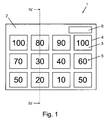
- the FIG. 1 It shows a plan view of an extended surface 2 of the device 1.
- This surface 2 is intended to serve as a target surface for a ball, wherein a player or athlete must try with the ball to hit certain areas of the target surface by the Ball either throws or shoots.
- the embodiment is substantially similar to the known football goal wall, but instead of two holes, for example, twelve rectangular areas 3 of the target area arranged in a matrix with three rows and four columns can be targeted by the user (in the following description, indications such as "Row”, “column”, “vertical” and “horizontal” to the orientation shown in the figures).
- each of the twelve areas 3 is a sensor array with an associated sensor array (see FIG. FIGS. 2 to 4 ), by which an impact of a ball on the respective sensor field can be detected.
- the sensor arrays 3 are identified by frame 4 printed on the target surface 1, and each sensor field 3 is assigned a scoring value indicated by a number 5 also printed on it.
- an electronic display 6, preferably a digital display, is provided to ever For example, according to the game mode, the sensor field 3 hit with the last shot or throw, or its score, the sum of the points scored after several throws or shots and / or a remaining score, if a game mode is selected in which a player or athlete starts from a starting point value by suitable hits, whose scores are successively subtracted from the starting point value, must reach the value zero. In addition, on the display 6 at several players or athletes that player or athlete can be displayed, which is currently or next in the row.
- the display 6 is preferably part of an evaluation unit or control unit which is adapted to determine the sensor field 3 taken on the basis of signals supplied by the sensor arrangements and to control the display 6 in the manner suitable for the desired display.
- a remote control can be provided which can be connected to the evaluation unit or control via a cable or wirelessly.
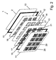
- the device 1 is constructed inter alia of several flexible layers or layers.
- the front side of the device 1 with the target surface 2 is provided by a front outer layer 10, and the back surface of the device 1 opposite the target surface 2 is provided by a rear outer layer 11.
- the two outer layers 10, 11, which may be provided for example in the form of suitable films there are three further layers in the form of two sensor films 12, 13 and an insulating layer 14 arranged between them, the sensor film 12 adjacent to the front outer layer 10 and the sensor film 14 is disposed adjacent to the rear outer layer 11.
- All the layers 10 to 14 correspond in shape to the shape of the device 1 and are arranged one above the other in the stated order and, for example, along their edges, along a part of their edges or over the entire surface connected to each other.
- one or more frames 15 are provided, e.g. between the outer layers 10, 11 and the adjacent sensor foils 12, 13 may be arranged along their edges.
- Such frame 15, which may be made of PVC, must be designed so that a folding or folding of the device 1 in the manner described in more detail below is possible.
- the layers 10 to 14 and the optionally present frame 15 in combination form a flexible planar element.
- each conductor pattern 16 and 17 On the insulating layer 14 facing surface of the two sensor films 12, 13, a respective conductor pattern 16 and 17 is applied, which can be formed for example by printed carbon.
- the conductor pattern 16 of the sensor film 12 is more detailed in FIG. 3a and the conductor pattern 17 of the sensor film 13 is shown in more detail in FIG FIG. 3b shown.
- each conductor pattern 16, 17 has a number of twelve fields 20 and 21 corresponding in shape, size and arrangement to the sensor fields 3 and the areas of the target area 2 defined by the frames 4 printed thereon.
- each of the fields 20 and each of the fields 21 is arranged under a different one of the areas of the target area defined by the frames 4, the frames 4 characterizing the position of the edges of the respective fields 20 and 21. Therefore, both the fields 20 and the Fields 21 are also arranged in a matrix with three rows and four columns.
- the arrays 20 of each column are connected in series by interconnect lines 22a, 22b, 22c, and 22d, respectively, and the interconnect lines 22a, 22b, 22c, and 22d merge into a drop line 23a, 23b, 23c, and 23d, respectively. which are electrically isolated from each other and connected to the evaluation unit (not shown).
- each column of fields 20 of the conductor pattern 16 is separately connected to the evaluation unit, wherein the fields 20 of different columns are electrically isolated from each other.
- the conductor pattern 17 has the arrays 21 of each row connected in series through interconnect lines 24a, 24b and 24c, respectively, and the interconnect lines 24a, 24b and 24c each pass into a terminal line 25a, 25b, 25c which are electrically isolated from each other and to the evaluation unit (not shown) are connected.
- each row of panels 21 of the conductor pattern 17 is separately connected to the evaluation unit, with the panels 21 of different rows being electrically isolated from each other.
- the insulating layer 14 has twelve regions 26, which correspond in their shape, size and arrangement of the sensor fields 3 and the fields 20, 21 and their expansion in FIG. 2 graphically indicated by a respective frame.
- the regions 26 are characterized in that a multiplicity of holes 27 are formed in them through the insulating layer 14.
- the described arrangement of the sensor films 12, 13, the insulation layer 14, the conductor pattern 16, 17 and the areas 26 with holes 27 in the insulation layer 14 twelve sensor arrays are formed, each of which is assigned to one of the sensor fields 3 and through one of the fields 20th of the conductor pattern 16, one of the fields 21 of the conductor pattern 17 and one of the hole regions 26 is formed and via respective ones of the connection line arrangements 22a, 22b, 22c, 22d and 24a, 24b, 24c and the connection lines 23a, 23b, 23c, 23d and 25a, 25b , 25c is connected to the evaluation unit.
- the conductors of the fields 20, 21 are normally kept separated from each other by the insulating layer 14 in each sensor arrangement.
- the lead 23a, 23b, 23c and 23d associated with the closed circuit identifies the column of the contacted sensor array 2, while due to the electrical connection of the rows of fields 21 of the conductor pattern 17, that connecting line 25a, 25b or 25b, which belongs to the closed circuit, identifies the row of the hit sensor field 2.
- the closed circuit uniquely identifies the actuated sensor arrangement, and thus unambiguously identifies the sensor field 2 that has been hit, which can therefore be determined by the evaluation unit.
- each of the pockets 28 corresponds again to the arrangement of Sensor field 2, so that each of the plates 29 seen from the target surface forms a rigid base for one of the sensor fields 2.
- the plates 29 cover at least the surface of the respectively associated sensor field 2.
- the pockets 28 are indicated by a frame, but their main part is omitted in each case to make the plates 29 arranged in them visible.
- the pockets 28 may have, for example, laterally an opening which can be closed, for example, by a hook-and-loop fastener, in order to be able to remove or replace the panels 29 as needed.
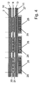
- FIG. 4 is a sectional view taken along the line IV-IV of FIG. 1 shown, from the described sequence of layers or layers 10 to 14 and the arrangement of the fields 20, 21 of the line assemblies 16 and 17, the holes 27 and the pockets 28 and plates 29 can be seen.
- the limitations of the sensor arrangements which also define the sensor fields 3 on the target surface 2.
- the frames 15 have been omitted.
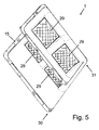
- the device 1 can be folded one or more times between groups of adjacent plates 29. This is in FIG. 5 shown in which the device 1 has been folded twice, namely once between the middle two columns of plates 29 by forming a crease line along the arrow 30 and then between the lower two rows of plates 29 by forming a crease line along the arrow 31st It should be noted that the pockets 28 for visualizing the plates 29 are indicated only by dashed lines.
Landscapes
- Health & Medical Sciences (AREA)
- General Health & Medical Sciences (AREA)
- Physical Education & Sports Medicine (AREA)
- Force Measurement Appropriate To Specific Purposes (AREA)
- Measurement Of Length, Angles, Or The Like Using Electric Or Magnetic Means (AREA)
Claims (15)
- Dispositif de détection et d'affichage de la percussion d'une balle avec un élément flexible étendu en surface (10-15) dont une surface (2) met à disposition une surface cible pour une balle et qui présente une multitude de champs de détecteur électriques (3) espacés l'un de l'autre, répartis sur la surface cible, qui sont définis respectivement par un arrangement de détecteur (20, 21, 26) qui est configuré pour donner, en service lors de la percussion d'une balle sur l'un des champs de détecteur (3), un signal électrique caractéristique pour le champ de détecteur respectif (3),
caractérisé en ce que le dispositif présente de plus un nombre d'éléments en forme de plaque (29) rigides séparés, espacés l'un de l'autre, qui correspond au nombre des champs de détecteur (3), éléments dont chacun est assigné à un autre des champs de détecteur (3) et est placé sur ou dans l'élément flexible étendu en surface (10-15) de telle manière que l'arrangement de détecteur (20, 21, 26) du champ de détecteur respectif (3) se trouve entre l'élément en forme de plaque respectif (29) et la surface cible, les champs de détecteur (3) et les éléments en forme de plaque correspondants (29) étant placés et formés de telle manière que le dispositif peut être plié à la manière d'une natte en le pliant entre des groupes d'éléments en forme de plaque voisins (29). - Dispositif selon la revendication 1 pour lequel l'élément flexible étendu en surface (10-15) est prévu en forme de natte en plusieurs couches.
- Dispositif selon la revendication 1 ou la revendication 2 pour lequel les éléments en forme de plaque (29) sont placés dans des poches (28) qui sont configurées sur la surface de l'élément flexible étendu en surface (10-15) opposée à la surface cible ou dans l'élément flexible étendu en surface (10-15).
- Dispositif selon l'une des revendications précédentes pour lequel les éléments en forme de plaque (29) sont placés en pouvant être enlevés sur ou dans l'élément flexible étendu en surface (10-15).
- Dispositif selon l'une des revendications précédentes pour lequel des éléments de fixation pour la fixation de l'élément flexible étendu en surface (10-15) sont placés le long du bord de l'élément flexible étendu en surface (10-15) dans un cadre.
- Dispositif selon l'une des revendications précédentes qui présente de plus une unité d'exploitation qui est reliée électriquement aux arrangements de détecteur (20, 21, 26) et qui est adaptée pour déterminer à partir des signaux électriques fournis par les arrangements de détecteur (20, 21, 26) sur lequel des champs de détecteur (3) une balle a percuté.
- Dispositif selon la revendication 6 pour lequel l'unité d'exploitation présente un affichage électronique (6) et l'unité d'exploitation est adaptée pour fournir, en service lors de la percussion d'une balle sur l'un des champs de détecteur (3), un signal électrique à l'affichage électronique (6) par lequel une indication du champ de détecteur touché (3) ou une valeur de points attribuée au champ de détecteur touche est affichée par l'affichage électronique ou est combinée arithmétiquement à un chiffre affiché sur l'affichage électronique (6) avant la percussion de la balle.
- Dispositif selon l'une des revendications précédentes pour lequel au moins les sections de l'élément étendu en surface qui forment les surfaces extérieures de l'élément flexible étendu en surface (10-15) sont configurées en nylon, en polyester ou en PVC.
- Dispositif selon l'une des revendications précédentes pour lequel chacun des arrangements de détecteur (20, 21, 26) présente un ou plusieurs commutateurs sensibles à la pression qui est actionné en exerçant une pression perpendiculairement à la surface cible à la position du commutateur sensible à la pression et qui, en service, ferme un circuit de courant qui est caractéristique pour fournir le signal caractéristique pour l'arrangement de détecteur (20, 21, 26).
- Dispositif selon la revendication 9 pour lequel l'élément flexible étendu en surface présente l'une au-dessus de l'autre- une première couche (12) d'un matériau isolant électriquement,- une seconde couche (13) d'un matériau isolant électriquement et- une troisième couche (14) d'un matériau isolant électriquement qui est placée entre la première (12) et la seconde couche (13) et qui présente une multitude de trous (27),un dessin de conducteurs électriques (16, 17) étant respectivement appliqué sur les surfaces tournées l'une vers l'autre de la première (12) et de la seconde couche (13), conducteurs qui sont placés de telle manière que chaque commutateur sensible à la pression est formé par au moins une section d'un conducteur électrique sur la première couche (12), au moins une section d'un conducteur électrique sur la seconde couche (13) et d'un des trous (27) dans la troisième couche (14), les sections de conducteur respectives étant placées à des extrémités opposées du trou respectif (27) et pouvant être amenées en contact par la pression à travers le trou si bien qu'un circuit de courant électrique se ferme qui est caractéristique pour fournir le signal caractéristique pour le champ de détecteur (3) auquel appartient le commutateur sensible à la pression respectif.
- Dispositif selon la revendication 10 pour lequel la première couche (12) et/ou la seconde couche (13) est configurée en nylon, en polyester ou en PVC.
- Dispositif selon la revendication 10 ou la revendication 11 pour lequel des conducteurs électriques sont formés par des pistes conductives imprimées sur la première (12) et sur la seconde couche (13).
- Dispositif selon l'une des revendications 10 à 12 pour lequel la troisième couche (14) est formée par un matériau du type éponge.
- Dispositif selon l'une des revendications 10 à 13 qui présente de plus une couche antérieure (10) qui met à disposition la surface cible et une couche postérieure (11) qui met à dispositif la surface de l'élément flexible étendu en surface (10-15) opposée à la surface cible, la première couche (12), la seconde couche (13) et la troisième couche (14) étant placées entre la couche antérieure (10) et la couche postérieure (11).
- Dispositif selon les revendications 3 et 14 pour lequel les poches (28) sont configurées sur la surface orientée vers l'extérieur de la couche postérieure (11) ou sur la surface orientée vers l'intérieur de la couche postérieure (11).
Applications Claiming Priority (1)
| Application Number | Priority Date | Filing Date | Title |
|---|---|---|---|
| DE201020001945 DE202010001945U1 (de) | 2010-02-07 | 2010-02-07 | Vorrichtung zum Detektieren und Anzeigen des Auftreffens eines Balles |
Publications (2)
| Publication Number | Publication Date |
|---|---|
| EP2353669A1 EP2353669A1 (fr) | 2011-08-10 |
| EP2353669B1 true EP2353669B1 (fr) | 2013-03-20 |
Family
ID=42146049
Family Applications (1)
| Application Number | Title | Priority Date | Filing Date |
|---|---|---|---|
| EP20100186460 Not-in-force EP2353669B1 (fr) | 2010-02-07 | 2010-10-04 | Dispositif de détection et d'affichage de la percussion d'une balle |
Country Status (5)
| Country | Link |
|---|---|
| EP (1) | EP2353669B1 (fr) |
| DE (1) | DE202010001945U1 (fr) |
| DK (1) | DK2353669T3 (fr) |
| ES (1) | ES2421399T3 (fr) |
| WO (1) | WO2011095627A1 (fr) |
Families Citing this family (3)
| Publication number | Priority date | Publication date | Assignee | Title |
|---|---|---|---|---|
| ES2427489B1 (es) | 2013-04-17 | 2014-07-08 | Foxtenn Bgreen, S. L. | Método y sistema para juzgar si un elemento esférico bota dentro o fuera de unas zonas de juego |
| FR3009970A1 (fr) * | 2013-09-03 | 2015-03-06 | Inventive | Cible d'entrainement pour l'analyse de l'impact d'une balle |
| GB2568479A (en) * | 2017-11-16 | 2019-05-22 | Aung Joseph | A sporting apparatus |
Family Cites Families (6)
| Publication number | Priority date | Publication date | Assignee | Title |
|---|---|---|---|---|
| US4824107A (en) * | 1985-10-10 | 1989-04-25 | French Barry J | Sports scoring device including a piezoelectric transducer |
| GB0021325D0 (en) * | 2000-08-31 | 2000-10-18 | Smith & Nephew | Rehabilitation device |
| DE50206826D1 (de) | 2001-07-27 | 2006-06-22 | Jan Helming | Spielgerät nach art einer torwand |
| US7060000B2 (en) * | 2001-10-11 | 2006-06-13 | Carlson Carl A | Game and exercise device and method |
| US8096900B2 (en) | 2004-03-19 | 2012-01-17 | Sports Innovation As | Mat for sport and games |
| US20080293522A1 (en) * | 2007-05-26 | 2008-11-27 | Kaleel Edward M | Tennis practice target and display |
-
2010
- 2010-02-07 DE DE201020001945 patent/DE202010001945U1/de not_active Expired - Lifetime
- 2010-10-04 ES ES10186460T patent/ES2421399T3/es active Active
- 2010-10-04 EP EP20100186460 patent/EP2353669B1/fr not_active Not-in-force
- 2010-10-04 DK DK10186460T patent/DK2353669T3/da active
-
2011
- 2011-02-07 WO PCT/EP2011/051759 patent/WO2011095627A1/fr not_active Ceased
Also Published As
| Publication number | Publication date |
|---|---|
| EP2353669A1 (fr) | 2011-08-10 |
| WO2011095627A1 (fr) | 2011-08-11 |
| DK2353669T3 (da) | 2013-06-24 |
| DE202010001945U1 (de) | 2010-05-06 |
| ES2421399T3 (es) | 2013-09-02 |
Similar Documents
| Publication | Publication Date | Title |
|---|---|---|
| WO2012072242A2 (fr) | Dispositif de jeu électronique | |
| EP2353669B1 (fr) | Dispositif de détection et d'affichage de la percussion d'une balle | |
| DE102007050062A1 (de) | Vorrichtung zur Erfassung, Auswertung und Anzeige von Daten | |
| EP1412033B1 (fr) | Appareil de jeu | |
| DE4135877A1 (de) | Matte oder platte | |
| DE202011051533U1 (de) | Spielsystem | |
| DE202021106826U1 (de) | Bandensystem und dessen Anordnung an einem Aktionsbereich | |
| DE3840476A1 (de) | Trefferanzeige fuer ballspiele | |
| DE102011016600A1 (de) | Anzeige- und Zählvorrichtung | |
| DE9402137U1 (de) | Sensorische Sport-Trefferfläche | |
| DE202021000950U1 (de) | Ballspielwand | |
| DE102017102191A1 (de) | Torwandspielsystem und Verfahren zum Betrieb eines Torwandspielsystems | |
| DE2049090A1 (de) | Spielzeug Schießanlage | |
| DE202006000799U1 (de) | Simulator-Vorrichtung | |
| DE4327433A1 (de) | Sensorische Sport-Trefferfläche | |
| DE10044356C1 (de) | Tanzbrett mit Verbindungsvorrichtung | |
| DE102016107470B4 (de) | System und Verfahrem zum Identifizieren von Objekten auf einem Touchscreen | |
| DE2723092A1 (de) | Fussballspiel | |
| DE20311917U1 (de) | Abschlagsmatte für einen Golfball | |
| DE20211332U1 (de) | Druckaufnehmer nach Art einer Folientastatur mit großflächigem Raster | |
| WO2018141930A1 (fr) | Installation de jeu de ballon et procédé pour l'enregistrement et l'évaluation du déroulement de jeu d'une telle installation de jeu de ballon | |
| DE202015003884U1 (de) | Parkouraufbau | |
| DE202008001765U1 (de) | Kreuzförmige Vorrichtung zum Torwandschiessen, Fußballspielen, Zielen und Werfen | |
| DE10216292A1 (de) | Elektrische Signalanlage für ein Tennisfeld | |
| DE202015102512U1 (de) | Spielraum |
Legal Events
| Date | Code | Title | Description |
|---|---|---|---|
| PUAI | Public reference made under article 153(3) epc to a published international application that has entered the european phase |
Free format text: ORIGINAL CODE: 0009012 |
|
| AK | Designated contracting states |
Kind code of ref document: A1 Designated state(s): AL AT BE BG CH CY CZ DE DK EE ES FI FR GB GR HR HU IE IS IT LI LT LU LV MC MK MT NL NO PL PT RO RS SE SI SK SM TR |
|
| AX | Request for extension of the european patent |
Extension state: BA ME |
|
| 17P | Request for examination filed |
Effective date: 20120208 |
|
| 17Q | First examination report despatched |
Effective date: 20120601 |
|
| GRAP | Despatch of communication of intention to grant a patent |
Free format text: ORIGINAL CODE: EPIDOSNIGR1 |
|
| GRAS | Grant fee paid |
Free format text: ORIGINAL CODE: EPIDOSNIGR3 |
|
| GRAA | (expected) grant |
Free format text: ORIGINAL CODE: 0009210 |
|
| AK | Designated contracting states |
Kind code of ref document: B1 Designated state(s): AL AT BE BG CH CY CZ DE DK EE ES FI FR GB GR HR HU IE IS IT LI LT LU LV MC MK MT NL NO PL PT RO RS SE SI SK SM TR |
|
| REG | Reference to a national code |
Ref country code: GB Ref legal event code: FG4D Free format text: NOT ENGLISH |
|
| REG | Reference to a national code |
Ref country code: CH Ref legal event code: EP |
|
| REG | Reference to a national code |
Ref country code: IE Ref legal event code: FG4D Free format text: LANGUAGE OF EP DOCUMENT: GERMAN |
|
| REG | Reference to a national code |
Ref country code: AT Ref legal event code: REF Ref document number: 601685 Country of ref document: AT Kind code of ref document: T Effective date: 20130415 |
|
| REG | Reference to a national code |
Ref country code: DE Ref legal event code: R096 Ref document number: 502010002601 Country of ref document: DE Effective date: 20130516 |
|
| REG | Reference to a national code |
Ref country code: DK Ref legal event code: T3 |
|
| REG | Reference to a national code |
Ref country code: CH Ref legal event code: NV Representative=s name: R. A. EGLI AND CO. PATENTANWAELTE, CH |
|
| PG25 | Lapsed in a contracting state [announced via postgrant information from national office to epo] |
Ref country code: LT Free format text: LAPSE BECAUSE OF FAILURE TO SUBMIT A TRANSLATION OF THE DESCRIPTION OR TO PAY THE FEE WITHIN THE PRESCRIBED TIME-LIMIT Effective date: 20130320 Ref country code: BG Free format text: LAPSE BECAUSE OF FAILURE TO SUBMIT A TRANSLATION OF THE DESCRIPTION OR TO PAY THE FEE WITHIN THE PRESCRIBED TIME-LIMIT Effective date: 20130620 Ref country code: SE Free format text: LAPSE BECAUSE OF FAILURE TO SUBMIT A TRANSLATION OF THE DESCRIPTION OR TO PAY THE FEE WITHIN THE PRESCRIBED TIME-LIMIT Effective date: 20130320 Ref country code: NO Free format text: LAPSE BECAUSE OF FAILURE TO SUBMIT A TRANSLATION OF THE DESCRIPTION OR TO PAY THE FEE WITHIN THE PRESCRIBED TIME-LIMIT Effective date: 20130620 |
|
| REG | Reference to a national code |
Ref country code: NL Ref legal event code: T3 |
|
| REG | Reference to a national code |
Ref country code: LT Ref legal event code: MG4D |
|
| PG25 | Lapsed in a contracting state [announced via postgrant information from national office to epo] |
Ref country code: FI Free format text: LAPSE BECAUSE OF FAILURE TO SUBMIT A TRANSLATION OF THE DESCRIPTION OR TO PAY THE FEE WITHIN THE PRESCRIBED TIME-LIMIT Effective date: 20130320 Ref country code: SI Free format text: LAPSE BECAUSE OF FAILURE TO SUBMIT A TRANSLATION OF THE DESCRIPTION OR TO PAY THE FEE WITHIN THE PRESCRIBED TIME-LIMIT Effective date: 20130320 Ref country code: GR Free format text: LAPSE BECAUSE OF FAILURE TO SUBMIT A TRANSLATION OF THE DESCRIPTION OR TO PAY THE FEE WITHIN THE PRESCRIBED TIME-LIMIT Effective date: 20130621 Ref country code: LV Free format text: LAPSE BECAUSE OF FAILURE TO SUBMIT A TRANSLATION OF THE DESCRIPTION OR TO PAY THE FEE WITHIN THE PRESCRIBED TIME-LIMIT Effective date: 20130320 |
|
| REG | Reference to a national code |
Ref country code: ES Ref legal event code: FG2A Ref document number: 2421399 Country of ref document: ES Kind code of ref document: T3 Effective date: 20130902 |
|
| PG25 | Lapsed in a contracting state [announced via postgrant information from national office to epo] |
Ref country code: RS Free format text: LAPSE BECAUSE OF FAILURE TO SUBMIT A TRANSLATION OF THE DESCRIPTION OR TO PAY THE FEE WITHIN THE PRESCRIBED TIME-LIMIT Effective date: 20130320 Ref country code: HR Free format text: LAPSE BECAUSE OF FAILURE TO SUBMIT A TRANSLATION OF THE DESCRIPTION OR TO PAY THE FEE WITHIN THE PRESCRIBED TIME-LIMIT Effective date: 20130320 |
|
| PG25 | Lapsed in a contracting state [announced via postgrant information from national office to epo] |
Ref country code: SK Free format text: LAPSE BECAUSE OF FAILURE TO SUBMIT A TRANSLATION OF THE DESCRIPTION OR TO PAY THE FEE WITHIN THE PRESCRIBED TIME-LIMIT Effective date: 20130320 Ref country code: CZ Free format text: LAPSE BECAUSE OF FAILURE TO SUBMIT A TRANSLATION OF THE DESCRIPTION OR TO PAY THE FEE WITHIN THE PRESCRIBED TIME-LIMIT Effective date: 20130320 Ref country code: EE Free format text: LAPSE BECAUSE OF FAILURE TO SUBMIT A TRANSLATION OF THE DESCRIPTION OR TO PAY THE FEE WITHIN THE PRESCRIBED TIME-LIMIT Effective date: 20130320 Ref country code: IS Free format text: LAPSE BECAUSE OF FAILURE TO SUBMIT A TRANSLATION OF THE DESCRIPTION OR TO PAY THE FEE WITHIN THE PRESCRIBED TIME-LIMIT Effective date: 20130720 Ref country code: PT Free format text: LAPSE BECAUSE OF FAILURE TO SUBMIT A TRANSLATION OF THE DESCRIPTION OR TO PAY THE FEE WITHIN THE PRESCRIBED TIME-LIMIT Effective date: 20130722 Ref country code: RO Free format text: LAPSE BECAUSE OF FAILURE TO SUBMIT A TRANSLATION OF THE DESCRIPTION OR TO PAY THE FEE WITHIN THE PRESCRIBED TIME-LIMIT Effective date: 20130320 |
|
| PG25 | Lapsed in a contracting state [announced via postgrant information from national office to epo] |
Ref country code: CY Free format text: LAPSE BECAUSE OF FAILURE TO SUBMIT A TRANSLATION OF THE DESCRIPTION OR TO PAY THE FEE WITHIN THE PRESCRIBED TIME-LIMIT Effective date: 20130320 Ref country code: PL Free format text: LAPSE BECAUSE OF FAILURE TO SUBMIT A TRANSLATION OF THE DESCRIPTION OR TO PAY THE FEE WITHIN THE PRESCRIBED TIME-LIMIT Effective date: 20130320 |
|
| PGFP | Annual fee paid to national office [announced via postgrant information from national office to epo] |
Ref country code: DK Payment date: 20131010 Year of fee payment: 4 |
|
| PLBE | No opposition filed within time limit |
Free format text: ORIGINAL CODE: 0009261 |
|
| STAA | Information on the status of an ep patent application or granted ep patent |
Free format text: STATUS: NO OPPOSITION FILED WITHIN TIME LIMIT |
|
| PGFP | Annual fee paid to national office [announced via postgrant information from national office to epo] |
Ref country code: BE Payment date: 20131014 Year of fee payment: 4 |
|
| 26N | No opposition filed |
Effective date: 20140102 |
|
| REG | Reference to a national code |
Ref country code: DE Ref legal event code: R097 Ref document number: 502010002601 Country of ref document: DE Effective date: 20140102 |
|
| PG25 | Lapsed in a contracting state [announced via postgrant information from national office to epo] |
Ref country code: MC Free format text: LAPSE BECAUSE OF FAILURE TO SUBMIT A TRANSLATION OF THE DESCRIPTION OR TO PAY THE FEE WITHIN THE PRESCRIBED TIME-LIMIT Effective date: 20130320 |
|
| REG | Reference to a national code |
Ref country code: IE Ref legal event code: MM4A |
|
| PG25 | Lapsed in a contracting state [announced via postgrant information from national office to epo] |
Ref country code: IE Free format text: LAPSE BECAUSE OF NON-PAYMENT OF DUE FEES Effective date: 20131004 |
|
| REG | Reference to a national code |
Ref country code: DK Ref legal event code: EBP Effective date: 20141031 |
|
| PG25 | Lapsed in a contracting state [announced via postgrant information from national office to epo] |
Ref country code: SM Free format text: LAPSE BECAUSE OF FAILURE TO SUBMIT A TRANSLATION OF THE DESCRIPTION OR TO PAY THE FEE WITHIN THE PRESCRIBED TIME-LIMIT Effective date: 20130320 |
|
| REG | Reference to a national code |
Ref country code: CH Ref legal event code: PL |
|
| PG25 | Lapsed in a contracting state [announced via postgrant information from national office to epo] |
Ref country code: BE Free format text: LAPSE BECAUSE OF NON-PAYMENT OF DUE FEES Effective date: 20141031 Ref country code: TR Free format text: LAPSE BECAUSE OF FAILURE TO SUBMIT A TRANSLATION OF THE DESCRIPTION OR TO PAY THE FEE WITHIN THE PRESCRIBED TIME-LIMIT Effective date: 20130320 |
|
| PG25 | Lapsed in a contracting state [announced via postgrant information from national office to epo] |
Ref country code: MK Free format text: LAPSE BECAUSE OF FAILURE TO SUBMIT A TRANSLATION OF THE DESCRIPTION OR TO PAY THE FEE WITHIN THE PRESCRIBED TIME-LIMIT Effective date: 20130320 Ref country code: CH Free format text: LAPSE BECAUSE OF NON-PAYMENT OF DUE FEES Effective date: 20141031 Ref country code: HU Free format text: LAPSE BECAUSE OF FAILURE TO SUBMIT A TRANSLATION OF THE DESCRIPTION OR TO PAY THE FEE WITHIN THE PRESCRIBED TIME-LIMIT; INVALID AB INITIO Effective date: 20101004 Ref country code: LU Free format text: LAPSE BECAUSE OF NON-PAYMENT OF DUE FEES Effective date: 20131004 Ref country code: LI Free format text: LAPSE BECAUSE OF NON-PAYMENT OF DUE FEES Effective date: 20141031 |
|
| PG25 | Lapsed in a contracting state [announced via postgrant information from national office to epo] |
Ref country code: MT Free format text: LAPSE BECAUSE OF FAILURE TO SUBMIT A TRANSLATION OF THE DESCRIPTION OR TO PAY THE FEE WITHIN THE PRESCRIBED TIME-LIMIT Effective date: 20130320 |
|
| PG25 | Lapsed in a contracting state [announced via postgrant information from national office to epo] |
Ref country code: DK Free format text: LAPSE BECAUSE OF NON-PAYMENT OF DUE FEES Effective date: 20141031 |
|
| REG | Reference to a national code |
Ref country code: FR Ref legal event code: PLFP Year of fee payment: 6 |
|
| PGFP | Annual fee paid to national office [announced via postgrant information from national office to epo] |
Ref country code: NL Payment date: 20160121 Year of fee payment: 6 |
|
| PGFP | Annual fee paid to national office [announced via postgrant information from national office to epo] |
Ref country code: IT Payment date: 20160122 Year of fee payment: 6 Ref country code: ES Payment date: 20160122 Year of fee payment: 6 |
|
| PGFP | Annual fee paid to national office [announced via postgrant information from national office to epo] |
Ref country code: GB Payment date: 20160122 Year of fee payment: 6 Ref country code: FR Payment date: 20160121 Year of fee payment: 6 |
|
| REG | Reference to a national code |
Ref country code: AT Ref legal event code: MM01 Ref document number: 601685 Country of ref document: AT Kind code of ref document: T Effective date: 20151004 |
|
| PG25 | Lapsed in a contracting state [announced via postgrant information from national office to epo] |
Ref country code: AT Free format text: LAPSE BECAUSE OF NON-PAYMENT OF DUE FEES Effective date: 20151004 |
|
| REG | Reference to a national code |
Ref country code: NL Ref legal event code: MM Effective date: 20161101 |
|
| GBPC | Gb: european patent ceased through non-payment of renewal fee |
Effective date: 20161004 |
|
| REG | Reference to a national code |
Ref country code: FR Ref legal event code: ST Effective date: 20170630 |
|
| PG25 | Lapsed in a contracting state [announced via postgrant information from national office to epo] |
Ref country code: GB Free format text: LAPSE BECAUSE OF NON-PAYMENT OF DUE FEES Effective date: 20161004 Ref country code: FR Free format text: LAPSE BECAUSE OF NON-PAYMENT OF DUE FEES Effective date: 20161102 |
|
| PGFP | Annual fee paid to national office [announced via postgrant information from national office to epo] |
Ref country code: DE Payment date: 20170428 Year of fee payment: 7 |
|
| PG25 | Lapsed in a contracting state [announced via postgrant information from national office to epo] |
Ref country code: NL Free format text: LAPSE BECAUSE OF NON-PAYMENT OF DUE FEES Effective date: 20161101 |
|
| PG25 | Lapsed in a contracting state [announced via postgrant information from national office to epo] |
Ref country code: IT Free format text: LAPSE BECAUSE OF NON-PAYMENT OF DUE FEES Effective date: 20161004 |
|
| REG | Reference to a national code |
Ref country code: DE Ref legal event code: R119 Ref document number: 502010002601 Country of ref document: DE |
|
| PG25 | Lapsed in a contracting state [announced via postgrant information from national office to epo] |
Ref country code: ES Free format text: LAPSE BECAUSE OF NON-PAYMENT OF DUE FEES Effective date: 20161005 |
|
| REG | Reference to a national code |
Ref country code: ES Ref legal event code: FD2A Effective date: 20180628 |
|
| PG25 | Lapsed in a contracting state [announced via postgrant information from national office to epo] |
Ref country code: DE Free format text: LAPSE BECAUSE OF NON-PAYMENT OF DUE FEES Effective date: 20180501 |
|
| PG25 | Lapsed in a contracting state [announced via postgrant information from national office to epo] |
Ref country code: AL Free format text: LAPSE BECAUSE OF FAILURE TO SUBMIT A TRANSLATION OF THE DESCRIPTION OR TO PAY THE FEE WITHIN THE PRESCRIBED TIME-LIMIT Effective date: 20130320 |