EP2353707A1 - Mischer mit Prallfläche - Google Patents
Mischer mit Prallfläche Download PDFInfo
- Publication number
- EP2353707A1 EP2353707A1 EP10151872A EP10151872A EP2353707A1 EP 2353707 A1 EP2353707 A1 EP 2353707A1 EP 10151872 A EP10151872 A EP 10151872A EP 10151872 A EP10151872 A EP 10151872A EP 2353707 A1 EP2353707 A1 EP 2353707A1
- Authority
- EP
- European Patent Office
- Prior art keywords
- mass
- boiler
- tool
- wall
- shaft
- Prior art date
- Legal status (The legal status is an assumption and is not a legal conclusion. Google has not performed a legal analysis and makes no representation as to the accuracy of the status listed.)
- Granted
Links
Images

Classifications
-
- B—PERFORMING OPERATIONS; TRANSPORTING
- B01—PHYSICAL OR CHEMICAL PROCESSES OR APPARATUS IN GENERAL
- B01F—MIXING, e.g. DISSOLVING, EMULSIFYING OR DISPERSING
- B01F27/00—Mixers with rotary stirring devices in fixed receptacles; Kneaders
- B01F27/60—Mixers with rotary stirring devices in fixed receptacles; Kneaders with stirrers rotating about a horizontal or inclined axis
- B01F27/72—Mixers with rotary stirring devices in fixed receptacles; Kneaders with stirrers rotating about a horizontal or inclined axis with helices or sections of helices
- B01F27/721—Mixers with rotary stirring devices in fixed receptacles; Kneaders with stirrers rotating about a horizontal or inclined axis with helices or sections of helices with two or more helices in the same receptacle
- B01F27/722—Mixers with rotary stirring devices in fixed receptacles; Kneaders with stirrers rotating about a horizontal or inclined axis with helices or sections of helices with two or more helices in the same receptacle the helices closely surrounded by a casing
- B01F27/7221—Mixers with rotary stirring devices in fixed receptacles; Kneaders with stirrers rotating about a horizontal or inclined axis with helices or sections of helices with two or more helices in the same receptacle the helices closely surrounded by a casing the stirrers being composed of helices and paddles on the same shaft, e.g. helically arranged ovally shaped paddles
-
- A—HUMAN NECESSITIES
- A23—FOODS OR FOODSTUFFS; TREATMENT THEREOF, NOT COVERED BY OTHER CLASSES
- A23G—COCOA; COCOA PRODUCTS, e.g. CHOCOLATE; SUBSTITUTES FOR COCOA OR COCOA PRODUCTS; CONFECTIONERY; CHEWING GUM; ICE-CREAM; PREPARATION THEREOF
- A23G1/00—Cocoa; Cocoa products, e.g. chocolate; Substitutes therefor
- A23G1/0003—Processes of manufacture not relating to composition or compounding ingredients
- A23G1/0026—Mixing; Roller milling for preparing chocolate
- A23G1/0036—Conching
- A23G1/0043—Circular conching, i.e. circular motion
-
- A—HUMAN NECESSITIES
- A23—FOODS OR FOODSTUFFS; TREATMENT THEREOF, NOT COVERED BY OTHER CLASSES
- A23G—COCOA; COCOA PRODUCTS, e.g. CHOCOLATE; SUBSTITUTES FOR COCOA OR COCOA PRODUCTS; CONFECTIONERY; CHEWING GUM; ICE-CREAM; PREPARATION THEREOF
- A23G1/00—Cocoa; Cocoa products, e.g. chocolate; Substitutes therefor
- A23G1/04—Apparatus specially adapted for manufacture or treatment of cocoa or cocoa products
- A23G1/10—Mixing apparatus; Roller mills for preparing chocolate
-
- B—PERFORMING OPERATIONS; TRANSPORTING
- B01—PHYSICAL OR CHEMICAL PROCESSES OR APPARATUS IN GENERAL
- B01F—MIXING, e.g. DISSOLVING, EMULSIFYING OR DISPERSING
- B01F27/00—Mixers with rotary stirring devices in fixed receptacles; Kneaders
- B01F27/05—Stirrers
- B01F27/07—Stirrers characterised by their mounting on the shaft
- B01F27/072—Stirrers characterised by their mounting on the shaft characterised by the disposition of the stirrers with respect to the rotating axis
- B01F27/0724—Stirrers characterised by their mounting on the shaft characterised by the disposition of the stirrers with respect to the rotating axis directly mounted on the rotating axis
-
- B—PERFORMING OPERATIONS; TRANSPORTING
- B01—PHYSICAL OR CHEMICAL PROCESSES OR APPARATUS IN GENERAL
- B01F—MIXING, e.g. DISSOLVING, EMULSIFYING OR DISPERSING
- B01F27/00—Mixers with rotary stirring devices in fixed receptacles; Kneaders
- B01F27/05—Stirrers
- B01F27/11—Stirrers characterised by the configuration of the stirrers
- B01F27/112—Stirrers characterised by the configuration of the stirrers with arms, paddles, vanes or blades
- B01F27/1125—Stirrers characterised by the configuration of the stirrers with arms, paddles, vanes or blades with vanes or blades extending parallel or oblique to the stirrer axis
- B01F27/11251—Stirrers characterised by the configuration of the stirrers with arms, paddles, vanes or blades with vanes or blades extending parallel or oblique to the stirrer axis having holes in the surface
-
- B—PERFORMING OPERATIONS; TRANSPORTING
- B01—PHYSICAL OR CHEMICAL PROCESSES OR APPARATUS IN GENERAL
- B01F—MIXING, e.g. DISSOLVING, EMULSIFYING OR DISPERSING
- B01F27/00—Mixers with rotary stirring devices in fixed receptacles; Kneaders
- B01F27/05—Stirrers
- B01F27/11—Stirrers characterised by the configuration of the stirrers
- B01F27/114—Helically shaped stirrers, i.e. stirrers comprising a helically shaped band or helically shaped band sections
- B01F27/1145—Helically shaped stirrers, i.e. stirrers comprising a helically shaped band or helically shaped band sections ribbon shaped with an open space between the helical ribbon flight and the rotating axis
-
- B—PERFORMING OPERATIONS; TRANSPORTING
- B01—PHYSICAL OR CHEMICAL PROCESSES OR APPARATUS IN GENERAL
- B01F—MIXING, e.g. DISSOLVING, EMULSIFYING OR DISPERSING
- B01F27/00—Mixers with rotary stirring devices in fixed receptacles; Kneaders
- B01F27/05—Stirrers
- B01F27/11—Stirrers characterised by the configuration of the stirrers
- B01F27/19—Stirrers with two or more mixing elements mounted in sequence on the same axis
- B01F27/192—Stirrers with two or more mixing elements mounted in sequence on the same axis with dissimilar elements
- B01F27/1921—Stirrers with two or more mixing elements mounted in sequence on the same axis with dissimilar elements comprising helical elements and paddles
-
- B—PERFORMING OPERATIONS; TRANSPORTING
- B01—PHYSICAL OR CHEMICAL PROCESSES OR APPARATUS IN GENERAL
- B01F—MIXING, e.g. DISSOLVING, EMULSIFYING OR DISPERSING
- B01F27/00—Mixers with rotary stirring devices in fixed receptacles; Kneaders
- B01F27/60—Mixers with rotary stirring devices in fixed receptacles; Kneaders with stirrers rotating about a horizontal or inclined axis
- B01F27/72—Mixers with rotary stirring devices in fixed receptacles; Kneaders with stirrers rotating about a horizontal or inclined axis with helices or sections of helices
- B01F27/721—Mixers with rotary stirring devices in fixed receptacles; Kneaders with stirrers rotating about a horizontal or inclined axis with helices or sections of helices with two or more helices in the same receptacle
- B01F27/722—Mixers with rotary stirring devices in fixed receptacles; Kneaders with stirrers rotating about a horizontal or inclined axis with helices or sections of helices with two or more helices in the same receptacle the helices closely surrounded by a casing
-
- B—PERFORMING OPERATIONS; TRANSPORTING
- B01—PHYSICAL OR CHEMICAL PROCESSES OR APPARATUS IN GENERAL
- B01F—MIXING, e.g. DISSOLVING, EMULSIFYING OR DISPERSING
- B01F35/00—Accessories for mixers; Auxiliary operations or auxiliary devices; Parts or details of general application
- B01F35/50—Mixing receptacles
-
- B—PERFORMING OPERATIONS; TRANSPORTING
- B01—PHYSICAL OR CHEMICAL PROCESSES OR APPARATUS IN GENERAL
- B01F—MIXING, e.g. DISSOLVING, EMULSIFYING OR DISPERSING
- B01F35/00—Accessories for mixers; Auxiliary operations or auxiliary devices; Parts or details of general application
- B01F35/90—Heating or cooling systems
Definitions
- the invention relates to a device for mixing and kneading of masses, in particular of chocolate masses, as well as a method for mixing and kneading of masses, in particular chocolate masses.
- the components of the mass are first mixed together and the matrix is homogeneous and plastic during mixing and optionally when kneading.
- the components of the composition are solid and / or liquid components, ie dry ingredients, such as cocoa powder, granular granulated sugar or milk powder, liquids and / or pasty masses.
- devices for mixing which have a boiler with a driven shaft, wherein on the shaft tools, in particular mixing, homogenization, shearing, scraping and / or conveying tools are arranged.
- Mixing devices generally have a boiler with an inner wall that at least partially simulates the outer surface of a rotating body. This is in particular a cylinder jacket.
- the inner wall can also correspond to a conical body, such as a cone.
- the rotating tools can then brush along a major portion of the interior wall of the kettle.
- the mixing and kneading is usually carried out in a double cylinder trough with two axially parallel rotating shafts.
- the boiler Preference is given to the boiler, or the axis of the body of revolution, and to arrange the shaft horizontally.
- the boiler can also be inclined or even vertically arranged, so that the mass, supported by gravity, is driven along the boiler axis.
- Mixers with essentially horizontally arranged waves are referred to below as horizontal mixers.
- the mass In the mixer, the mass is driven by the tools around the shaft. In a horizontal mixer, the mass is lifted by the tools in the ascending direction, comes off the top of the tool and falls due to gravity through the space between the tool and shaft on the lower part of the inner wall of the boiler, from where it is in turn taken by the tools , The components of the mass mix and the mass is homogenized.
- the invention has for its object to provide an apparatus and a method with which the mixing and / or kneading processes are made more effective and the processed mass can be provided better and faster for subsequent processes.
- a device for mixing and kneading masses, in particular chocolate masses comprises a preferably horizontally arranged in normal use boiler with an inner wall, the at least partially, in particular to 50-90% of its surface, more particularly to 60-85%, more particularly to 70-80%, the outer surface a rotational body simulates, in particular a cylinder jacket.
- the device also comprises a shaft arranged in the boiler with at least one tool attached thereto.
- a shearing tool is preferably used for mixing and kneading.
- this has a greater distance from the boiler wall and thus enables shearing of the mass between the tool and the wall.
- At least one, in particular level, baffle surface is arranged in the vessel, which extends in the axial direction and which is located in particular outside and / or inside the outer surface of the rotation body. That is, the baffle is not part of the outer surface of the rotating body, in particular not part of the inner wall of the boiler, which has the contour of a rotating body.
- the entire mass or parts thereof can experience a compression that goes beyond the impact of the mass when it falls on the lower part of the inner wall of the boiler.
- the mass can be subjected to a kneading process.
- the path of the rotating tools must lead around the impact surface, for example, the tools can be driven by an eccentrically mounted axle and / or can be spring-mounted.
- the shaft is arranged coaxially with the axis of the rotary body.
- this means that the baffle is located outside the body of revolution.
- the boiler advantageously provides room for a free trajectory, in particular parabolic trajectory, of mass accelerated by the tool, in particular of mass accelerated tangentially from the inner wall.
- the baffle may then be mounted so that mass is thrown through the free trajectory space onto the surface.
- the interior of the boiler expands beyond the rotation body, so that a detachment edge is formed, from which the mass is accelerated tangentially to the sectional surface of the rotation body.
- the space for the trajectory is in the upper half, so that the accelerated mass passes through approximately a parabolic trajectory. At a suitable starting speed, the mass can then hit the impact surface.
- the space can be given by the fact that the boiler has a substantially parallel to the axis arranged neck-like opening with at least one shoulder surface.
- the opening can also be used to fill and / or aerate and / or clean the boiler and / or to replace the tools.
- a mixer in particular as described above, consisting of a preferably horizontally arranged when used as intended boiler with an at least partially cylindrical inner wall, with a shaft and at least one attached tool, in particular a stripping tool, wherein the boiler according to the invention has a neck-like opening arranged parallel to the axis of the rotary body with at least one shoulder surface which extends substantially over the entire length of the boiler.
- An opening arranged in a horizontal mixer in the upper half of the boiler can on the one hand be used for filling and / or ventilating and / or cleaning the boiler and / or for exchanging the tools. It can also give room for the trajectory of accelerated mass in the mixer.
- At least one shoulder surface of the opening forms a baffle surface.
- the neck-like opening can also be formed so that it has two shoulder surfaces, each forming baffles, so that the mass can be thrown in both directions of rotation of the tools against the baffle.
- the opening angle of the axially extending opening is chosen so that for a wide range of masses to be mixed, the masses on the one hand do not spray out of the mixer, on the other hand reach the baffle.
- a cover such as a hinged lid, provided for the opening.
- the tool is designed as a screw conveyor. This puts the mass on the one hand in a rotation and throws it against the baffle, on the other hand, the mass is driven in the axial direction through the mixer.
- the direction of conveyance can be reversed if the direction of rotation is reversed, so that the mass changes during a change the directions of rotation in the axial direction can be moved back and forth.
- the device has a speed control and / or a speed controller for the rotational speed of the shaft and the tools. This serves in particular to adapt the flight or parabolic trajectory to the properties of the mass, which is given for example by composition, quantity, specific gravity, consistency, etc.
- the mass for example, on the one hand does not fly out of the boiler and on the other hand a large part of the mass hits the baffle with a given arrangement of the baffle.
- the tangential velocity which depends on the number of revolutions of the shaft and the properties of the mass, must lie within a suitable value range when detaching from the inner wall of the mass. The necessary speed, or number of revolutions, can easily be determined by routine tests.
- the baffle can be provided changeable, for example, the position of the baffle can be displaced and / or the height and / or the surface size variable and / or the entire baffle can be interchangeable, depending on which surface depending on the filled mass and the adjustable rotational speeds is desired.
- the trajectory of the mass can also be limited with an additional component, for example an inserted wedge.
- the object underlying the invention is also achieved by a device for mixing and kneading of fat masses, in particular of chocolate masses, in particular as described above, consisting of a preferably horizontally arranged in normal use boiler with an at least partially cylindrical inner wall having a shaft and at least one tool attached thereto. These are in particular a shearing tool.
- a device for mixing and kneading of fat masses, in particular of chocolate masses, in particular as described above consisting of a preferably horizontally arranged in normal use boiler with an at least partially cylindrical inner wall having a shaft and at least one tool attached thereto. These are in particular a shearing tool.
- two counter-rotating worm belts or parts of opposite worm belts are attached to the shaft, which preferably, at least partially, overlap.
- the bands preferably overlap near the outlet of the boiler, which may be in the center of the boiler.
- the worm belts or worm belt pieces are in particular designed in such a way that they simultaneously act as shearing tools.
- the shaft drive can then take place only in one direction and the mass is driven by right and left-handed worm belts in opposite directions.
- the worm conveyors of one direction of rotation can be continuous or present as individual pieces.
- the individual pieces are each parts of screw conveyors. They can be spaced apart.
- the imaginary connecting line of the individual pieces may have the form of a continuous screw conveyor belt.
- the opposing pintle bands overlapping near the outlet are preferably arranged such that the mass is forced toward the overlapping region.
- at least one stirring paddle can be arranged on the shaft, which enhances the mixing effect.
- the stirring paddle may be shorter than the tool, as mixing is particularly important at lower rotational speeds, where the influence of centrifugal force is less than that of gravity and the mass is predominantly in the lower half of the vessel.
- the device has a tempering device.
- the boiler and / or the inner wall and / or the filled mass can be warmed and / or cooled. This is particularly beneficial in the processing of chocolate mass, which is initially heated to soften the mass that may or may not be cooled in a later stage after mechanical energy has been introduced into the mass.
- Chocolate mass is advantageously processed at a temperature between 35 ° C and 50 ° C degrees.
- the object underlying the invention is also achieved by a method for mixing and kneading of masses, in particular chocolate masses, wherein the mass in a mixer, in particular as described above, from a tool, in particular a stripping tool, is thrown against a baffle.
- the mass is subjected to a kneading process by the spinning process and the upsetting on impact with the impact surface. This is about the processing of the mass with tools in which, for example, shear forces act on the mass, or falling down of the mass due to gravity, since the speed component in the spin direction, in particular the tangential velocity, is used with.
- the mass undergoes two compressions during one revolution of the shaft, on the one hand upon impact with the baffle surface, on the other hand when it falls down on the underside of the boiler.
- the mass is kneaded very effectively. Because per circulation more than a compression takes place and because these compression take place in different directions, it can also come to a folding of doughy mass, which further favors the kneading process.
- the mass is accelerated in a mixer with a boiler having at least one partially cylindrical inner wall, in particular a horizontal mixer, tangentially to the cylindrical inner wall.
- the mass then travels through the trajectory of an oblique litter before striking the baffle.
- the rotational speed can be optimally adapted to the conditions in the boiler, in particular the properties of the mass, so that a large part of the mass hits the baffle surface at high speed and experiences a compression there.
- the speed of the at least one tool is controlled or regulated, in particular for adjusting the flight or Parabelbahn to the properties of the mass, such as composition, amount, specific gravity, consistency, temperature, etc ..
- the appropriate speed is determined empirically depending on the formulation of the mass.
- the mass is first moved in a horizontal mixer at a first speed, wherein the components of the mass are predominantly mixed.
- the mass is then moved at a second speed, wherein the mass is thrown against the baffle and mainly kneaded.
- the speeds are preferably adjusted so that the theoretical impact point lies in the center of the impact surface.
- the process or the quality of the mixed material can be regulated by means of a torque absorption and / or power consumption.
- the mass can be tempered during processing.
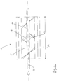
- FIG. 1 shows a schematic sectional view of an inventive device for mixing and kneading 1.
- the shown Horizontal mixer 1 has a boiler 2 with an inner wall 3, which at least partially corresponds to a cylinder jacket 4.
- the boiler has a neck-like opening 5.
- a lateral wall 6 of the opening 5 is formed as a shoulder surface 7a, which acts as a baffle 8. This lies outside of the cylinder jacket 4.
- the baffle 8 is arranged in the embodiment shown in the vertical. It can alternatively include smaller angles, between 45 and 90 degrees, with the horizontal.
- the baffle 8 opposite shoulder surface 7b of the opening 5 is optimized with an inserted wedge 9. This prevents leakage of heat from the typically tempered boiler 2 and spilling over of mass.
- the wedge 9 may be an integral part of the device 1 or be removable. In that case, for example, it may be taken away for cleaning, or it may not be used at all depending on the mass to be worked.
- the mixer 1 is operated with a uniaxial mixer, wherein the shaft 11 is arranged coaxially with the cylinder surface 4.
- the mixer consists of two or more screw bands 10, which are driven with the shaft 11 on the inner wall 3 along.
- the worm belts 10 drive the mass not shown in the figure in the mixer 1 and shear it to the wall.
- the wedge 9 is designed so that within the neck-like opening 5 space 15 is provided for a free trajectory of accelerated by the tool mass.
- the mass When the mass reaches a separation edge 16 at the opening 5, it begins to follow a trajectory of an oblique throw, having an initial velocity in the tangential direction 12. If this tangential velocity is sufficiently high, which depends on the rotational speed of the shaft and the properties of the mass, the mass is thrown against the impact surface 8.
- the mass When hitting the baffle 8, the mass is compressed and then folded when falling down and resuming. In this way, the mass is subjected to a kneading process.
- FIG. 2 shows a plan view of a horizontal mixer 1 according to the invention.
- two right-handed and left-handed worm belts 10 are mounted, which overlap in the middle of the boiler 19, ie in the region of the outlet 18.
- the belts 10 drive the mass into the center of the boiler 19, resulting in a clean drain.
- the pitch of the screw conveyor 10 is preferably about 0.6 times the length of the kettle.
- the bands have a rectangular cross-section.
- the neck-like opening 5 extends parallel to the axis 17 of the rotary body practically over the entire length 14 of the mixer first
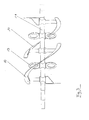
- FIG. 3 shows a plan view of a shaft 11 with first and second tools 10, 13.
- first and second tools 10, 13 can be attached to the shaft 11 inclined paddle 13.
Landscapes
- Chemical & Material Sciences (AREA)
- Chemical Kinetics & Catalysis (AREA)
- Life Sciences & Earth Sciences (AREA)
- Engineering & Computer Science (AREA)
- Food Science & Technology (AREA)
- Polymers & Plastics (AREA)
- Mixers Of The Rotary Stirring Type (AREA)
- Confectionery (AREA)
- Accessories For Mixers (AREA)
Abstract
Description
- Die Erfindung betrifft eine Vorrichtung zum Mischen und Kneten von Massen, insbesondere von Schokoladenmassen, sowie ein Verfahren zum Mischen und Kneten von Massen, insbesondere Schokoladenmassen.
- Bei der Herstellung und Bearbeitung insbesondere von Fettmassen wie Schokolade werden die Komponenten der Masse zunächst miteinander gemischt und die Grundmasse wird beim Mischen und gegebenenfalls beim Kneten homogen und plastisch. Bei den Komponenten der Masse handelt es sich um feste und/oder flüssige Bestandteile, also Trockenbestandteile, wie Kakaopulver, körniger Kristallzucker oder Milchpulver, Flüssigkeiten und/oder pastöse Massen.
- Aus den Druckschriften
DE1782585 ,EP 565887 DE19637098 sind beispielsweise Vorrichtungen zum Mischen bekannt, die einen Kessel mit einer angetriebenen Welle aufweisen, wobei an der Welle Werkzeuge, insbesondere Misch-, Homogenisierungs-, Scher-, Schabe- und/oder Förderwerkzeuge angeordnet sind. - Vorrichtungen zum Mischen weisen in der Regel einen Kessel mit einer Innenwand auf, die wenigstens teilweise die Aussenfläche eines Rotationskörpers nachbildet. Dabei handelt es sich insbesondere um einen Zylindermantel. Die Innenwand kann aber auch einem konischen Körper, wie einen Kegel, entsprechen. Die rotierenden Werkzeuge können dann an einem Grossteil der Innenwand des Kessels entlang streifen. Das Mischen und Kneten wird in der Regel in einem Doppelzylindertrog mit zwei achsparallel rotierenden Wellen durchgeführt.
- Bevorzugt sind der Kessel, bzw. die Achse des Rotationskörpers, und die Welle horizontal anzuordnen. Der Kessel kann allerdings auch geneigt oder sogar vertikal angeordnet sein, sodass die Masse, von der Schwerkraft unterstützt, entlang der Kesselachse getrieben wird. Mischer mit im Wesentlichen horizontal angeordneten Wellen werden im Folgenden Horizontalmischer genannt.
- In der Regel weisen die Kessel zum Einfüllen der Masse im oberen Bereich eine Einfüllöffnung auf, während am tiefsten Punkt des Kessels ein Auslauf angeordnet ist.
- In dem Mischer wird die Masse von den Werkzeugen um die Welle herum getrieben. In einem Horizontalmischer wird die Masse von den Werkzeugen in aufsteigender Richtung angehoben, löst sich oben angekommen vom Werkzeug und fällt aufgrund der Schwerkraft durch den Zwischenraum zwischen Werkzeug und Welle auf den unteren Teil der Innenwand des Kessels, von wo sie wiederum von den Werkzeugen aufgenommen wird. Die Komponenten der Masse vermischen sich dabei und die Masse wird homogenisiert.
- Ausgehend von dem Bekannten liegt der Erfindung die Aufgabe zugrunde, eine Vorrichtung und ein Verfahren bereitzustellen, mit welchem die Misch- und/oder Knetvorgänge effektiver gestaltet werden und die verarbeitete Masse besser und schneller für nachfolgende Prozesse bereitgestellt werden kann.
- Die Aufgabe wird gelöst durch eine Vorrichtung zum Mischen und Kneten von Massen, insbesondere von Schokoladenmassen. Diese umfasst einen bei bestimmungsgemässem Gebrauch bevorzugt horizontal anzuordnenden Kessel mit einer Innenwand, die wenigstens teilweise, insbesondere zu 50-90% ihrer Fläche, weiter insbesondere zu 60-85%, weiter insbesondere zu 70-80%, die Aussenfläche eines Rotationskörpers nachbildet, insbesondere einen Zylindermantel.
- Die Vorrichtung umfasst ausserdem eine im Kessel angeordnete Welle mit mindestens einem daran befestigten Werkzeug. Zum Mischen und Kneten wird bevorzugt ein Scherwerkzeug verwendet. Dieses hat im Gegensatz zu einem, beispielsweise in einer Conche verwendeten, Schabwerkzeug einen grösseren Abstand zur Kesselwand und ermöglicht somit ein Scheren der Masse zwischen Werkzeug und Wand.
- Erfindungsgemäss ist in dem Kessel mindestens eine, insbesondere ebene, Prallfläche angeordnet, die sich in axialer Richtung erstreckt und die sich insbesondere ausserhalb und/oder innerhalb der Aussenfläche des Rotationskörpers befindet. Das heisst, die Prallfläche ist nicht Teil der Aussenfläche des Rotationskörpers, insbesondere nicht Teil der Innenwand des Kessels, der die Kontur eines Rotationskörpers besitzt.
- In einer solchen Vorrichtung können nicht nur Komponenten einer Masse bewegt und dadurch vermischt werden. An der erfindungsgemässen Prallfläche kann die gesamte Masse oder Teile davon eine Stauchung erfahren, die über das Auftreffen der Masse beim Herunterfallen auf den unteren Teil der Innenwand des Kessels hinausgeht. Die Masse kann so einem Knetvorgang unterzogen werden.
- Ist die Prallfläche innerhalb der Rotationskörpers angeordnet, muss der Weg der umlaufenden Werkzeuge um die Prallfläche herumführen, die Werkzeuge können dafür beispielsweise von einer exzentrisch angebrachten Achse angetrieben werden und/oder federnd gelagert sein.
- In einer bevorzugten Ausführung der Erfindung ist die Welle koaxial mit der Achse des Rotationskörpers angeordnet. Bei der Verwendung von starren Werkzeugen bedeutet dies, dass die Prallfläche ausserhalb des Rotationskörpers angeordnet ist.
- Um den Kneteffekt zu begünstigen, bietet der Kessel vorteilhafterweise Raum für einen freie Flugbahn, insbesondere Parabelbahn, von durch das Werkzeug beschleunigter Masse, insbesondere von tangential von der Innenwand aus beschleunigter Masse. Die Prallfläche kann dann so angebracht sein, dass Masse durch den Raum für die freie Flugbahn auf die Fläche geschleudert wird. Bevorzugt weitet sich der Innenraum des Kessels über den Rotationskörper hinaus, sodass eine Ablösekante entsteht, von der aus die Masse tangential zur Schnittfläche des Rotationskörpers beschleunigt wird.
- Bei im Wesentlichen horizontal angeordneten Mischern befindet sich der Raum für die Flugbahn in der oberen Hälfte, so dass die beschleunigte Masse in etwa eine Parabelbahn durchläuft. Bei geeigneter Startgeschwindigkeit kann die Masse danach auf die Prallfläche treffen.
- Der Raum kann dadurch gegeben sein, dass der Kessel eine im Wesentlichen parallel zur Achse angeordnete halsartige Öffnung mit mindestens einer Schulterfläche aufweist. Die Öffnung kann ausserdem zum Befüllen und/oder Belüften und/oder Reinigen des Kessels und/oder zum Austausch der Werkzeuge genutzt werden.
- Die Aufgabe wird weiterhin gelöst durch einen Mischer, insbesondere wie oben beschrieben, bestehend aus einem bei bestimmungsgemässem Gebrauch bevorzugt horizontal anzuordnenden Kessel mit einer wenigstens teilweise zylindrischen Innenwand, mit einer Welle und mindestens einem daran befestigten Werkzeug, insbesondere einem Abstreifwerkzeug, wobei der Kessel erfindungsgemäss eine parallel zur Achse des Rotationskörpers angeordnete halsartige Öffnung mit mindestens einer Schulterfläche aufweist, die sich im Wesentlichen über die gesamte Länge des Kessels erstreckt.
- Eine bei einem Horizontalmischer in der oberen Hälfe des Kessels angeordnete Öffnung kann einerseits zum Befüllen und/oder Belüften und/oder Reinigen des Kessels und/oder zum Austausch der Werkzeuge genutzt werden. Sie kann auch Raum geben für die Flugbahn von im Mischer beschleunigter Masse.
- Bevorzugt bildet mindestens eine Schulterfläche der Öffnung eine Prallfläche. Die halsartige Öffnung kann auch so ausgebildet sein, dass sie zwei Schulterflächen aufweist, die jeweils Prallflächen bilden, sodass die Masse in beiden Drehrichtungen der Werkzeuge gegen die Prallfläche geschleudert werden kann.
- Der Öffnungswinkel der axial verlaufenen Öffnung ist so gewählt, dass für ein breites Spektrum der zu mischenden Massen die Massen einerseits nicht aus dem Mischer herausspritzen, andererseits die Prallfläche erreichen.
- Es kann eine Abdeckung, beispielsweise ein Klappdeckel, für die Öffnung vorgesehen sein.
- In einer vorteilhaften Ausführung der Erfindung ist das Werkzeug als Schneckenband ausgeführt. Dieses versetzt die Masse einerseits in eine Rotation und schleudert sie gegen die Prallfläche, andererseits wird die Masse in Axialrichtung durch den Mischer getrieben. Die Förderrichtung kann bei einer Umkehrung der Drehrichtung umgekehrt werden, sodass die Masse bei einem Wechsel der Drehrichtungen in Axialrichtung hin und her bewegt werden kann.
- In einer weiteren vorteilhaften Ausführung der Erfindung weist die Vorrichtung eine Geschwindigkeitssteuerung und/oder einen Geschwindigkeitsregler für die Drehgeschwindigkeit der Welle und der Werkzeuge auf. Diese dient insbesondere zur Anspassung der Flug- oder Parabelbahn an die Eigenschaften der Masse, die beispielsweise durch Zusammensetzung, die Menge, das spezifische Gewicht, die Konsistenz usw. gegeben ist.
- Mit einer Einstellung der Geschwindigkeit kann bei gegebener Anordnung der Prallfläche dafür gesorgt werden, dass die Masse zum Beispiel einerseits nicht aus dem Kessel herausfliegt und andererseits ein Grossteil der Masse auf die Prallfläche trifft. Dazu muss die Tangentialgeschwindigkeit, die von der Umdrehungszahl der Welle und den Eigenschaften der Masse abhängt, beim Ablösen von der Innenwand der Masse in einem geeigneten Wertebereich liegen. Die notwendige Geschwindigkeit, bzw. Umdrehungszahl, kann leicht durch Routineversuche ermittelt werden.
- Alternativ kann auch die Prallfläche veränderbar vorgesehen sein, beispielsweise kann die Position der Prallfläche verschiebbar und/oder die Höhe und/oder die Flächengrösse veränderbar sein und/oder die gesamte Prallfläche kann austauschbar sein, je nachdem, welche Auftrittsfläche in Abhängigkeit von der eingefüllten Masse und den einstellbaren Drehgeschwindigkeiten gewünscht ist. Alternativ kann die Flugbahn der Masse auch mit einem zusätzlichen Bauteil, zum Beispiel einem eingeschobenen Keil, begrenzt werden.
- Die der Erfindung zugrunde liegende Aufgabe wird ausserdem gelöst durch eine Vorrichtung zum Mischen und Kneten von Fettmassen, insbesondere von Schokoladenmassen, insbesondere wie oben beschrieben, bestehend aus einem bei bestimmungsgemässem Gebrauch bevorzugt horizontal anzuordnenden Kessel mit einer wenigstens teilweise zylindrischer Innenwand, der eine Welle und mindestens ein daran befestigten Werkzeug aufweist. Dabei handelt es sich insbesondere einem Scherwerkzeug. Erfindungsgemäss ist vorgesehen, dass an der Welle zwei gegenläufige Schneckenbänder oder Teile von gegenläufigen Schneckenbändern angebracht sind, die bevorzugt, zumindest teilweise, überlappen. Der Bänder überlappen bevorzugt in Nähe des Auslasses des Kessels, der sich in der Mitte des Kessels befinden kann.
- Die Schneckenbänder oder Schneckenbandstücke sind insbesondere so ausgeführt, dass sie gleichzeitig als Scherwerkzeug wirken.
- Der Wellenantrieb kann dann nur in einer Richtung erfolgen und die Masse wird durch rechts- und linkgängige Schneckenbänder in entgegen gesetzten Richtungen getrieben.
- Die Schneckenbänder einer Drehrichtung können zusammenhängend ausgeführt sein, oder als Einzelstücke vorliegen. Die Einzelstücke sind jeweils Teile von Schneckenbändern. Sie können voneinander beabstandet sein. Die gedachte Verbindungslinie der Einzelstücke kann die Form eines durchgehenden Schneckenbandes haben.
- Die in der Nähe des Auslasses, zum Beispiel in der Mitte des Kessels, überlappenden gegenläufigen Scheckenbänder sind bevorzugt so angeordnet, dass die Masse zu dem überlappenden Bereich hin getrieben wird. Dort befindet sich bevorzugt der Auslauf des Kessels, sodass für eine saubere Entleerung gesorgt werden kann. Zusätzlich kann auf der Welle mindestens ein Rührpaddel angeordnet sein, welches den Mischeffekt verstärkt.
- Das Rührpaddel kann kürzer als das Werkzeug sein, da das Mischen gerade bei kleineren Drehgeschwindigkeiten eine Rolle spielt, bei denen der Einfluss der Zentrifugalkraft im Vergleich zur Schwerkraft geringer ist und sich die Masse vorwiegend in der unteren Hälfte des Kessels befindet.
- In einer vorteilhaften Ausführung weist die Vorrichtung eine Temperiereinrichtung auf. Mit dieser können der Kessels und/oder die Innenwand und/oder die eingefüllte Masse gewärmt und/oder gekühlt werden. Dies ist besonders günstig bei der Verarbeitung von Schokoladenmasse, die anfangs erwärmt wird, um die Masse geschmeidig zu machen, die in einer späteren Phase, nachdem mechanische Energie in die Masse eingebracht wurde, gegebenenfalls noch gekühlt werden kann.
- Schokoladenmasse wird vorteilhafterweise bei einer Temperatur zwischen 35°C und 50°C Grad bearbeitet.
- Die der Erfindung zugrunde liegende Aufgabe wird ausserdem gelöst durch ein Verfahren zum Mischen und Kneten von Massen, insbesondere Schokoladenmassen, wobei die Masse in einem Mischer, insbesondere wie oben beschrieben, von einem Werkzeug, insbesondere einem Abstreifwerkzeug, gegen eine Prallfläche geschleudert wird.
- Durch den Schleudervorgang und das Stauchen beim Aufprall auf die Prallfläche wird die Masse einem Knetvorgang unterzogen. Dieser geht über die Benarbeitung der Masse mit Werkzeugen, bei der z.B. Scherkräfte auf die Masse wirken, oder das Herunterfallen der Masse aufgrund der Schwerkraft hinaus, da die Geschwindigkeitskomponente in der Schleuderrichtung, insbesondere die Tangentialgeschwindigkeit, mit ausgenutzt wird.
- In einem Horizontalmischer erfährt die Masse bei einem Umlauf der Welle zwei Stauchungen, zum einen beim Aufprall auf die Prallfläche, zum einen beim Herunterfallen auf die Unterseite des Kessels. Die Masse wird also sehr effektiv geknetet. Denn pro Umlauf findet mehr als eine Stauchung statt und weil diese Stauchungen in verschiedenen Richtungen stattfinden, kann es überdies zu einer Faltung der teigigen Masse kommen, was den Knetprozess weiter begünstigt.
- In einer vorteilhaften Ausführung des Verfahrens wird die Masse in einem Mischer mit einem wenigstens eine teilweise zylindrische Innenwand aufweisenden Kessel, insbesondere einem Horizontalmischer, tangential zu der zylindrischen Innenwand beschleunigt. Die Masse durchläuft dann die Flugbahn eines schrägen Wurfs, bevor sie auf die Prallfläche auftrifft.
- Bei dieser Anordnung kann die Drehgeschwindigkeit optimal an die Verhältnisse in dem Kessel, insbesondere die Eigenschaften der Masse, angepasst werden, sodass ein Grossteil der Masse mit hoher Geschwindigkeit auf die Prallfläche trifft und dort eine Stauchung erfährt.
- In einer vorzugsweisen Ausführung der Erfindung wird die Geschwindigkeit des mindestens einen Werkzeuges gesteuert oder geregelt, insbesondere zur Anspassung der Flug- oder Parabelbahn an die Eigenschaften der Masse, wie Zusammensetzung, Menge, spezifisches Gewicht, Konsistenz, Temperatur usw..
- Bevorzugt wird je nach Rezeptur der Masse die geeignete Drehzahl empirisch bestimmt.
- Bevorzugt wird die Masse in einem Horizontalmischer zunächst bei einer ersten Geschwindigkeit bewegt, wobei die Komponenten der Masse vorwiegend gemischt werden. Die Masse wird anschliessend bei einer zweiten Geschwindigkeit bewegt, wobei die Masse gegen die Prallfläche geschleudert und vorwiegend geknetet wird.
- Die Geschwindigkeiten sind so produktabhängig vorzugsweise so einzustellen, dass der theoretische Aufschlagpunkt in der Mitte der Prallfläche liegt.
- Der Prozess, bzw. die Qualität des Mischgutes kann mittels einer Drehmomentaufnahme und/oder einer Leistungsaufnahme geregelt werden.
- Zusätzlich kann die Masse während der Bearbeitung temperiert werden.
- Die Erfindung ist im Folgenden in Ausführungsbeispielen anhand von Zeichnungen näher erläutert.
- Es zeigen
- Figur 1
- eine schematische Schnittdarstellung einer erfindungsgemässen Vorrichtung;
- Figur 2
- eine Draufsicht auf eine erfindungsgemässen Vorrichtung;
- Figur 3
- eine Draufsicht auf eine Welle mit ersten und zweiten Werkzeugen.
-
Figur 1 zeigt eine schematische Schnittdarstellung einer erfindungsgemässen Vorrichtung zum Mischen und Kneten 1. Der gezeigte Horizontalmischer 1 besitzt einen Kessel 2 mit einer Innenwand 3, die wenigstens teilweise einem Zylindermantel 4 entspricht. - Der Kessel besitzt eine halsartige Öffnung 5. Eine seitliche Wand 6 der Öffnung 5 ist als Schulterfläche 7a ausgebildet, die als Prallfläche 8 wirkt. Diese liegt ausserhalb des Zylindermantels 4. Die Prallfläche 8 ist im gezeigeten Ausführungsbeispiel in der Vertikalen angeordnet. Sie kann alternativ mit der Horizontale kleinere Winkel, zwischen 45 und 90 Grad, einschliessen.
- Die der Prallfläche 8 gegenüberliegende Schulterfläche 7b der Öffnung 5 ist mit einem eingesetzten Keil 9 optimiert. Dieser verhindert ein Austreten von Wärme aus dem typischerweise temperierten Kessel 2 und das Überschwappen von Masse.
- Der Keil 9 kann fester Bestandteil der Vorrichtung 1 sein oder entfernbar sein. In dem Fall kann er zum Beispiel zum Reinigen weggenommen werden oder je nach zu bearbeitender Masse braucht er gar nicht benutzt werden.
- Im gezeigten Beispiel wird der Mischer 1 mit einem einachsigen Mischwerk betrieben, wobei die Welle 11 koaxial zur Zylinderfläche 4 angeordnet ist. Das Mischwerk besteht aus zwei oder mehreren Schneckenbändern 10, welche mit der Welle 11 an der Innenwand 3 entlang getrieben werden.
- Die Schneckenbänder 10 treiben die nicht in der Figur dargstellt Masse im Mischer 1 umher und scheren sie zu der Wand.
- Bei genügend hoher Umdrehungszahl ist die Zentrifugalkraft der Masse grösser als die Schwerkraft. In diesem Fall ist FROUDE-Zahl = Dk n2 π/g grösser als 1 (wobei Dk der Innendurchmesser des Kessels, n die Drehzahl des Mischwerks und g die Erdbeschleunigung ist).
- Der Keil 9 ist so ausgeführt, dass innerhalb der halsartigen Öffnung 5 Raum 15 für eine freie Flugbahn von durch das Werkzeug beschleunigter Masse geboten ist.
- Wenn die Masse eine Ablösekante 16 an der Öffnung 5 erreicht, beginnt sie, einer Flugbahn eines schrägen Wurfs zu folgen, wobei sie eine Anfangsgeschwindigkeit in Tangentialrichtung 12 besitzt. Ist diese Tangentialgeschwindigkeit genügend gross, was von der Umdrehungsgeschwindigkeit der Welle und den Eigenschaften der Masse abhängt, so wird die Masse gegen die Prallfläche 8 geschleudert.
- Die Geschwindigkeiten sind so produktabhängig so einzustellen, dass der theoretische Aufschlagpunkt auf halber Höhe der Schulterfläche 7 liegt.
- Von dort fällt die Masse aufgrund der Schwerkraft hinab in den Kessel 2 und wird von den Schneckenbändern 10 wieder aufgenommen und mitgezogen.
- Beim Auftreffen auf die Prallfläche 8 wird die Masse gestaucht und anschliessend beim Herunterfallen und Wiederaufnehmen gefaltet. Auf dieser Art wird die Masse einem Knetvorgang unterzogen.
-
Figur 2 zeigt eine Draufsicht auf einen erfindungsgemässen Horizontalmischers 1. - An der Welle 11 sind zwei rechts- und linksgängige Schneckenbänder 10 angebracht, die in der Kesselmitte 19, also im Bereich des Auslaufs 18, überlappen. Die Bänder 10 treiben die Masse in die Kesselmitte 19, was zu einer sauberen Entleerung führt.
- Die Steigung der Schneckenbänder 10 beträgt vorzugsweise in etwa das 0.6 fache der Kessellänge.
- Die Bänder haben einen rechteckigen Querschnitt. Die halsartige Öffnung 5 erstreckt sich parallel zur Achse 17 des Rotationskörpers praktisch über die gesamte Länge 14 des Mischers 1.
-
Figur 3 zeigt eine Draufsicht auf eine Welle 11 mit ersten und zweiten Werkzeugen 10, 13. Zusätzlich zu den Schneckenbändern 10 können an der Welle 11 schräg gestellte Rührpaddel 13 angebracht sein.
Claims (16)
- Vorrichtung zum Mischen und Kneten von Massen, insbesondere von Schokoladenmassen,- mit einem bevorzugt horizontal anzuordnenden Kessel (2) mit einer Innenwand (3),- wobei die Innenwand (3) des Kessels wenigstens teilweise, bevorzugt zu 60-90 % ihrer Fläche, der Aussenfläche eines Rotationskörpers nachbildet, insbesondere eines Zylindermantels (4),- und mit einer Welle (11) und mindestens einem daran befestigten Werkzeug (10, 13) insbesondere einem Scherwerkzeug,dadurch gekennzeichnet, dass
in dem Kessel (2) mindestens eine, insbesondere ebene, Prallfläche (8) angeordnet ist, die sich in axialer Richtung erstreckt und die sich insbesondere ausserhalb und/oder innerhalb der Aussenfläche des Rotationskörpers befindet. - Vorrichtung nach Anspruch 1, dadurch gekennzeichnet, dass die Welle (11) koaxial mit der Achse des Rotationskörpers angeordnet ist.
- Vorrichtung nach Anspruch 1 oder 2,
dadurch gekennzeichnet, dass
der Kessel (2) Raum (15) bietet für einen freie Flugbahn, insbesondere Parabelbahn, von durch das Werkzeug (10, 13) beschleunigter Masse, insbesondere von tangential von der Innenwand (3) aus beschleunigter Masse. - Vorrichtung nach einem der vorhergehenden Ansprüche, dadurch gekennzeichnet, dass der Kessel (2) eine parallel zur Achse (17) des Rotationskörpers angeordnete halsartige Öffnung (5) mit mindestens einer Schulterfläche (7a, 7b) aufweist.
- Vorrichtung zum Mischen und Kneten von Massen, insbesondere von Schokoladenmassen, insbesondere nach einem der vorhergehenden Ansprüche, bestehend aus einem bevorzugt horizontal anzuordnenden Kessel (2) mit einer wenigstens teilweise zylindrischen Innenwand (3), mit einer Welle (11) und mindestens einem daran befestigten Werkzeug (10, 13), insbesondere einem Scherwerkzeug, dadurch gekennzeichnet, dass
der Kessel (2) eine parallel zur Achse (17) des Zylinders angeordnete halsartige Öffnung (5) mit mindestens einer Schulterfläche (7a, 7b) aufweist, wobei sich die Öffnung (5) im Wesentlichen über die gesamte Länge (14) des Kessels (2) erstreckt. - Vorrichtung nach Anspruch 4 oder 5, dass
mindestens eine Schulterfläche (7a, 7b) der Öffnung eine Prallfläche (8) bildet. - Vorrichtung nach einem der vorhergehenden Ansprüche, dadurch gekennzeichnet, dass
das Werkzeug ein Schneckenband (10) ist. - Vorrichtung nach einem der vorhergehenden Ansprüche, dadurch gekennzeichnet, dass
die Vorrichtung eine Geschwindigkeitssteuerung und/oder einen Geschwindigkeitsregler für die Drehgeschwindigkeit der Welle aufweist, insbesondere zur Anspassung der Flug- oder Parabelbahn an die Eigenschaften der Masse. - Vorrichtung zum Mischen und Kneten von Fettmassen, insbesondere von Schokoladenmassen, insbesondere nach einem der vorhergehenden Ansprüche, bestehend aus einem bevorzugt horizontal anzuordnenden Kessel (2) mit einer wenigstens teilweise zylindrischen Innenwand (3), mit einer Welle (11) und mindestens einem daran befestigten Werkzeug (10, 13), insbesondere einem Scherwerkzeug, dadurch gekennzeichnet, dass an der Welle zwei gegenläufige Schneckenbänder (10) oder Teile von gegenläufigen Schneckenbändern (10) angebracht sind, die bevorzugt, zumindest teilweise, überlappen, bevorzugt in der Nähe des Auslasses des Kessels.
- Vorrichtung nach einem der vorhergehenden Ansprüche, dadurch gekennzeichnet, dass auf der Welle mindestens ein Rührpaddel (13) angeordnet ist.
- Vorrichtung nach einem der vorhergehenden Ansprüche, dadurch gekennzeichnet, dass
die Vorrichtung eine Temperiereinrichtung zum Wärmen und/oder Kühlen des Kessels und/oder der Innenwand und/oder der Masse aufweist. - Verfahren zum Mischen und Kneten von Massen, insbesondere Schokoladenmassen, dadurch gekennzeichnet, dass die Masse in einer Vorrichtung zum Mischen und Kneten, insbesondere gemäss Anspruch 1-11, von mindestens einem Werkzeug (10, 13), insbesondere einem Scherwerkzeug, gegen eine Prallfläche (8) geschleudert wird.
- Verfahren nach Anspruch 12, dadurch gekennzeichnet, dass die Masse in einer Vorrichtung zum Mischen und Kneten mit einem wenigstens eine teilweise zylindrische Innenwand (3) aufweisenden Kessel (2), insbesondere einem Horizontalmischer (1), tangential zu der zylindrischen Innenwand (3) beschleunigt wird und die Flugbahn eines schrägen Wurfs durchläuft, bevor sie auf die Prallfläche (8) auftrifft.
- Verfahren nach Anspruch 12 oder 13, dadurch gekennzeichnet, dass die Geschwindigkeit des mindestens einen Werkzeuges (10, 13) gesteuert oder geregelt wird, insbesondere zur Anpassung der Flug- oder Parabelbahn an die Eigenschaften der Masse.
- Verfahren nach einem der Ansprüche 12 bis 14, dadurch gekennzeichnet, dass die Masse in einem Horizontalmischer (1) zunächst bei einer ersten Geschwindigkeit bewegt wird, wobei die Komponenten der Masse vorwiegend gemischt werden, und die Masse anschliessend bei einer zweiten Geschwindigkeit bewegt wird, wobei die Masse gegen die Prallfläche (8) geschleudert und vorwiegend geknetet wird.
- Verfahren nach einem der Ansprüche 12 bis 15, dadurch gekennzeichnet, dass die Masse während der Bearbeitung temperiert wird.
Priority Applications (8)
| Application Number | Priority Date | Filing Date | Title |
|---|---|---|---|
| EP10151872.8A EP2353707B1 (de) | 2010-01-28 | 2010-01-28 | Vorrichtung und Verfahren zum Mischen und Kneten von Massen, insbesondere Schokoladenmassen |
| ES10151872.8T ES2437126T3 (es) | 2010-01-28 | 2010-01-28 | Dispositivo y método para mezclar y amasar masas, particularmente masas de chocolate |
| PCT/EP2011/051104 WO2011092230A1 (de) | 2010-01-28 | 2011-01-27 | Mischer mit prallfläche |
| JP2012550435A JP5818815B2 (ja) | 2010-01-28 | 2011-01-27 | 跳ね当て面を備えたミキサ |
| BR112012018655A BR112012018655A2 (pt) | 2010-01-28 | 2011-01-27 | misturador com face defletora |
| US13/574,857 US20130051173A1 (en) | 2010-01-28 | 2011-01-27 | Mixer Comprising a Deflector Surface |
| KR1020127020480A KR101853145B1 (ko) | 2010-01-28 | 2011-01-27 | 디플렉터 표면을 구비한 믹서 |
| CN201180006440.2A CN102711974B (zh) | 2010-01-28 | 2011-01-27 | 带有轧碎板的混合机 |
Applications Claiming Priority (1)
| Application Number | Priority Date | Filing Date | Title |
|---|---|---|---|
| EP10151872.8A EP2353707B1 (de) | 2010-01-28 | 2010-01-28 | Vorrichtung und Verfahren zum Mischen und Kneten von Massen, insbesondere Schokoladenmassen |
Publications (2)
| Publication Number | Publication Date |
|---|---|
| EP2353707A1 true EP2353707A1 (de) | 2011-08-10 |
| EP2353707B1 EP2353707B1 (de) | 2013-08-28 |
Family
ID=42237166
Family Applications (1)
| Application Number | Title | Priority Date | Filing Date |
|---|---|---|---|
| EP10151872.8A Active EP2353707B1 (de) | 2010-01-28 | 2010-01-28 | Vorrichtung und Verfahren zum Mischen und Kneten von Massen, insbesondere Schokoladenmassen |
Country Status (8)
| Country | Link |
|---|---|
| US (1) | US20130051173A1 (de) |
| EP (1) | EP2353707B1 (de) |
| JP (1) | JP5818815B2 (de) |
| KR (1) | KR101853145B1 (de) |
| CN (1) | CN102711974B (de) |
| BR (1) | BR112012018655A2 (de) |
| ES (1) | ES2437126T3 (de) |
| WO (1) | WO2011092230A1 (de) |
Cited By (4)
| Publication number | Priority date | Publication date | Assignee | Title |
|---|---|---|---|---|
| EP2742836A3 (de) * | 2012-12-14 | 2014-08-13 | Seb S.A. | Durchbrochenes, drehbares Arbeitsgerät für Elektrohaushaltsgerät zur Herstellung von Nahrungsmittel- und/oder Kosmetikzubereitungen |
| EP3059007A1 (de) * | 2015-02-23 | 2016-08-24 | Umicore AG & Co. KG | Rührer zum rühren von geschmolzenem glas, vorrichtung zum rühren von geschmolzenem glas mit solch einem rührer und verwendung solch eines rührers |
| FR3047402A1 (fr) * | 2016-02-09 | 2017-08-11 | Carrival | Machine alimentaire pour la preparation d’aligot |
| EP3241449A1 (de) | 2016-05-02 | 2017-11-08 | Bühler AG | Vorrichtung und verfahren zum bearbeiten von lebensmittelmassen |
Families Citing this family (7)
| Publication number | Priority date | Publication date | Assignee | Title |
|---|---|---|---|---|
| US10265668B2 (en) * | 2016-01-29 | 2019-04-23 | Sartorius Stedim Biotech Gmbh | Mixing methods |
| GB2550551A (en) * | 2016-05-12 | 2017-11-29 | Hewlett Packard Development Co Lp | Powder material mixer |
| DE102017001784B4 (de) * | 2017-02-24 | 2020-12-31 | Netzsch Feinmahltechnik Gmbh | Conchiervorrichtung und Verfahren zum Conchieren einer Produktmasse |
| WO2018196970A1 (en) * | 2017-04-26 | 2018-11-01 | Bühler AG | Self-optimizing, adaptive industrial chocolate production system, and corresponding method thereof |
| CN112006216A (zh) * | 2019-05-28 | 2020-12-01 | 株式会社沙迪克 | 粉粒体预加热装置及方法、粉粒体温度调节装置及方法 |
| JP7788136B2 (ja) * | 2021-09-03 | 2025-12-18 | 株式会社カジワラ | 撹拌処理装置 |
| CN114653240A (zh) * | 2022-04-17 | 2022-06-24 | 石河子大学 | 一种新型交错转轮式混合试验台 |
Citations (8)
| Publication number | Priority date | Publication date | Assignee | Title |
|---|---|---|---|---|
| DE1937268A1 (de) * | 1968-07-24 | 1970-08-27 | Cadbury Bros Ltd | Methode und Vorrichtungen zur Herstellung von Schokolade |
| DE1782585A1 (de) | 1968-09-20 | 1971-10-14 | Draiswerke Gmbh | Mischmaschine |
| US4606647A (en) * | 1984-08-17 | 1986-08-19 | Frye James A | Pin mixer |
| US5083506A (en) * | 1991-03-06 | 1992-01-28 | Blentech Corporation | Continuous compartmented mixer |
| EP0518025A2 (de) * | 1991-05-02 | 1992-12-16 | Richard Frisse Gmbh Maschinenfabrik | Conche und Verfahren zum Betrieb einer solchen |
| EP0565887A1 (de) | 1992-04-14 | 1993-10-20 | R. FRISSE GmbH | Maschine zum Bearbeiten von Schokolademassen und Verwendung zur Herstellung von Crumb |
| EP0632961A1 (de) * | 1993-07-06 | 1995-01-11 | Bühler Ag | Conche |
| DE19637098A1 (de) | 1996-09-12 | 1998-03-19 | Frisse Richard Maschf | Vorrichtung zum Mischen und/oder Verfeinern von Schokolademassen |
Family Cites Families (14)
| Publication number | Priority date | Publication date | Assignee | Title |
|---|---|---|---|---|
| US4733607A (en) * | 1985-10-07 | 1988-03-29 | Star Leonard J | Food processing machine |
| JPH021291U (de) * | 1988-06-14 | 1990-01-08 | ||
| US5501865A (en) * | 1991-04-30 | 1996-03-26 | Jacobs Suchard Ag | Milk chocolate and method of making same |
| JPH09201523A (ja) * | 1996-01-26 | 1997-08-05 | Kyushu Sangyo:Kk | 撹拌混合機 |
| US6517232B1 (en) * | 1996-05-20 | 2003-02-11 | Becker-Underwood, Inc. | Mixing systems |
| US6162496A (en) * | 1996-05-20 | 2000-12-19 | Blue; David | Method of mixing |
| US6129008A (en) * | 1996-09-12 | 2000-10-10 | Richard Frisse Gmbh | Apparatus for mixing and refining a chocolate mass |
| DK0931454T3 (da) * | 1998-01-22 | 2001-07-23 | Skiold Mullerup As | Apparat til findeling og blanding af foderkomponenter til dyrefoder |
| JP3946939B2 (ja) * | 2000-07-07 | 2007-07-18 | ▲高▼▲巣▼浩次 | 生分解処理装置とこれらを用いた有機廃棄物分解処理方法 |
| JP3704520B2 (ja) * | 2002-01-07 | 2005-10-12 | 森永製菓株式会社 | 混合装置 |
| JP3764130B2 (ja) * | 2002-06-11 | 2006-04-05 | 神鋼造機株式会社 | 混練混合解砕装置 |
| CN101584971A (zh) * | 2003-12-30 | 2009-11-25 | 株式会社千田工程 | 固化剂供给装置及比重调整装置 |
| US20060044935A1 (en) * | 2004-08-25 | 2006-03-02 | Benelli Brandon P | Method and system for producing a temperature profile in a food preparation container |
| EP2052773B1 (de) * | 2004-09-28 | 2012-07-18 | Basf Se | Mischkneter sowie Verwendung des Mischkneters zur Herstellung von Poly(meth)acrylaten |
-
2010
- 2010-01-28 ES ES10151872.8T patent/ES2437126T3/es active Active
- 2010-01-28 EP EP10151872.8A patent/EP2353707B1/de active Active
-
2011
- 2011-01-27 US US13/574,857 patent/US20130051173A1/en not_active Abandoned
- 2011-01-27 JP JP2012550435A patent/JP5818815B2/ja not_active Expired - Fee Related
- 2011-01-27 WO PCT/EP2011/051104 patent/WO2011092230A1/de not_active Ceased
- 2011-01-27 CN CN201180006440.2A patent/CN102711974B/zh active Active
- 2011-01-27 KR KR1020127020480A patent/KR101853145B1/ko not_active Expired - Fee Related
- 2011-01-27 BR BR112012018655A patent/BR112012018655A2/pt not_active Application Discontinuation
Patent Citations (8)
| Publication number | Priority date | Publication date | Assignee | Title |
|---|---|---|---|---|
| DE1937268A1 (de) * | 1968-07-24 | 1970-08-27 | Cadbury Bros Ltd | Methode und Vorrichtungen zur Herstellung von Schokolade |
| DE1782585A1 (de) | 1968-09-20 | 1971-10-14 | Draiswerke Gmbh | Mischmaschine |
| US4606647A (en) * | 1984-08-17 | 1986-08-19 | Frye James A | Pin mixer |
| US5083506A (en) * | 1991-03-06 | 1992-01-28 | Blentech Corporation | Continuous compartmented mixer |
| EP0518025A2 (de) * | 1991-05-02 | 1992-12-16 | Richard Frisse Gmbh Maschinenfabrik | Conche und Verfahren zum Betrieb einer solchen |
| EP0565887A1 (de) | 1992-04-14 | 1993-10-20 | R. FRISSE GmbH | Maschine zum Bearbeiten von Schokolademassen und Verwendung zur Herstellung von Crumb |
| EP0632961A1 (de) * | 1993-07-06 | 1995-01-11 | Bühler Ag | Conche |
| DE19637098A1 (de) | 1996-09-12 | 1998-03-19 | Frisse Richard Maschf | Vorrichtung zum Mischen und/oder Verfeinern von Schokolademassen |
Cited By (11)
| Publication number | Priority date | Publication date | Assignee | Title |
|---|---|---|---|---|
| EP2742836A3 (de) * | 2012-12-14 | 2014-08-13 | Seb S.A. | Durchbrochenes, drehbares Arbeitsgerät für Elektrohaushaltsgerät zur Herstellung von Nahrungsmittel- und/oder Kosmetikzubereitungen |
| EP3059007A1 (de) * | 2015-02-23 | 2016-08-24 | Umicore AG & Co. KG | Rührer zum rühren von geschmolzenem glas, vorrichtung zum rühren von geschmolzenem glas mit solch einem rührer und verwendung solch eines rührers |
| WO2016135084A1 (en) * | 2015-02-23 | 2016-09-01 | Umicore Ag & Co.Kg | Device for stirring molten glass |
| USD800807S1 (en) | 2015-02-23 | 2017-10-24 | Umicore Ag & Co. Kg | Stirrer |
| USD800808S1 (en) | 2015-02-23 | 2017-10-24 | Umicore Ag & Co. Kg | Stirrer |
| USD849070S1 (en) | 2015-02-23 | 2019-05-21 | Umicore Ag & Co. Kg | Stirrer |
| US10676385B2 (en) | 2015-02-23 | 2020-06-09 | Umicore Ag & Co. Kg | Device for stirring molten gas |
| USD918279S1 (en) | 2015-02-23 | 2021-05-04 | Umicore Ag & Co. Kg | Stirrer |
| FR3047402A1 (fr) * | 2016-02-09 | 2017-08-11 | Carrival | Machine alimentaire pour la preparation d’aligot |
| WO2017137686A1 (fr) * | 2016-02-09 | 2017-08-17 | Carrival | Machine alimentaire pour la préparation d'aligot |
| EP3241449A1 (de) | 2016-05-02 | 2017-11-08 | Bühler AG | Vorrichtung und verfahren zum bearbeiten von lebensmittelmassen |
Also Published As
| Publication number | Publication date |
|---|---|
| US20130051173A1 (en) | 2013-02-28 |
| JP5818815B2 (ja) | 2015-11-18 |
| CN102711974B (zh) | 2016-02-17 |
| JP2013517933A (ja) | 2013-05-20 |
| BR112012018655A2 (pt) | 2016-05-03 |
| CN102711974A (zh) | 2012-10-03 |
| KR20120115357A (ko) | 2012-10-17 |
| ES2437126T3 (es) | 2014-01-09 |
| KR101853145B1 (ko) | 2018-04-27 |
| EP2353707B1 (de) | 2013-08-28 |
| WO2011092230A1 (de) | 2011-08-04 |
Similar Documents
| Publication | Publication Date | Title |
|---|---|---|
| EP2353707B1 (de) | Vorrichtung und Verfahren zum Mischen und Kneten von Massen, insbesondere Schokoladenmassen | |
| DE3119971C2 (de) | ||
| EP2460581B1 (de) | Verfahren zum Mischen von pulver- und/oder granulatförmigen Stoffen sowie Mischmaschine | |
| EP3702023B1 (de) | Schräglagenmischer | |
| EP1191996B1 (de) | Knetmaschine mit dosiervorrichtung | |
| EP1121193A1 (de) | Zwangsmischer, insbesondere als betonmischer | |
| EP0565887B1 (de) | Maschine zum Bearbeiten von Schokolademassen und Verwendung zur Herstellung von Crumb | |
| EP3666382B1 (de) | Leicht handhabbare veredelung einer pflanzenkohle in einer zerkleinerungsvorrichtung mit hoher nachhaltigkeit der verwertung in futtermitteln und arzneimitteln | |
| EP3585179A1 (de) | Conchiervorrichtung und verfahren zum conchieren einer produktmasse | |
| EP1157736A1 (de) | Anlage und Verfahren zur quasi-kontinuierlichen Behandlung eines teilchenförmigen Gutes | |
| EP3473107A1 (de) | Vorrichtung und verfahren zum be- und verarbeiten von schokolade sowie verwendung einer universalmaschine dafür | |
| EP1273341A1 (de) | Verfahren zum vertikalen Mischen und Vorrichtung dazu | |
| DE69005433T2 (de) | Mühle zur herstellung einer suspension bestehend aus festen teilchen in einem fetten träger. | |
| DE2341639C3 (de) | Verfahren und Vorrichtung zum Herstellen von Schokoladenmassen | |
| DE2065028A1 (de) | Vorrichtung zum Mischen von gemahlenem Kaffee. Ausscheidung aus: 2022353 | |
| EP3102318B1 (de) | Verfahren und vorrichtung zum mischen und dosieren fester dosiergüter in eine trägerflüssigkeit | |
| DE2108181C3 (de) | Vorrichtung zum Aufbereiten, Mischen, Auflockern, Zerteilen oder Kühlen von körnigem Material, insbesondere Gießsand | |
| EP2488289B1 (de) | Verfahren und verwendung zur verfeinerung | |
| DE1266734B (de) | Vorrichtung zum kontinuierlichen Mischen, Verfluessigen, Veredeln und Aromenintensivieren von insbesondere Schokoladenmassen | |
| DE1945615A1 (de) | Verfahren und Anlage zum Verfluessigen und Verruehren raffinierter Schokolade | |
| DE10342982B3 (de) | Verfahren und Vorrichtung zur Durchmischung von gekochter Kartoffelsubstanz mit getrocknetem Kartoffelpulver | |
| DE1592618C (de) | Mischvorrichtung zur Herstellung eines streufahigen Dungemitteis aus Huhnermist und trockenem Kalk | |
| DE2314344B1 (de) | Mischer fuer die kontinuierliche Aufbereitung von fliessfaehigem Mischgut | |
| DE102005047518A1 (de) | Mischverfahren und Mischer mit mehreren Zonen | |
| DE19835347A1 (de) | Vorrichtung zum Conchieren von Schokoladenmassen |
Legal Events
| Date | Code | Title | Description |
|---|---|---|---|
| PUAI | Public reference made under article 153(3) epc to a published international application that has entered the european phase |
Free format text: ORIGINAL CODE: 0009012 |
|
| 17P | Request for examination filed |
Effective date: 20110629 |
|
| AK | Designated contracting states |
Kind code of ref document: A1 Designated state(s): AT BE BG CH CY CZ DE DK EE ES FI FR GB GR HR HU IE IS IT LI LT LU LV MC MK MT NL NO PL PT RO SE SI SK SM TR |
|
| AX | Request for extension of the european patent |
Extension state: AL BA RS |
|
| 17Q | First examination report despatched |
Effective date: 20110829 |
|
| GRAP | Despatch of communication of intention to grant a patent |
Free format text: ORIGINAL CODE: EPIDOSNIGR1 |
|
| RIC1 | Information provided on ipc code assigned before grant |
Ipc: B01F 15/06 20060101ALN20121008BHEP Ipc: B01F 7/08 20060101ALI20121008BHEP Ipc: B01F 15/00 20060101ALI20121008BHEP Ipc: A23G 1/10 20060101ALI20121008BHEP Ipc: A23G 1/00 20060101ALI20121008BHEP Ipc: B01F 7/00 20060101AFI20121008BHEP |
|
| REG | Reference to a national code |
Ref country code: DE Ref legal event code: R079 Ref document number: 502010004483 Country of ref document: DE Free format text: PREVIOUS MAIN CLASS: B01F0011020000 Ipc: B01F0007000000 |
|
| GRAP | Despatch of communication of intention to grant a patent |
Free format text: ORIGINAL CODE: EPIDOSNIGR1 |
|
| RIC1 | Information provided on ipc code assigned before grant |
Ipc: A23G 1/00 20060101ALI20130225BHEP Ipc: A23G 1/10 20060101ALI20130225BHEP Ipc: B01F 7/00 20060101AFI20130225BHEP Ipc: B01F 7/08 20060101ALI20130225BHEP Ipc: B01F 15/06 20060101ALN20130225BHEP Ipc: B01F 15/00 20060101ALI20130225BHEP |
|
| GRAS | Grant fee paid |
Free format text: ORIGINAL CODE: EPIDOSNIGR3 |
|
| GRAA | (expected) grant |
Free format text: ORIGINAL CODE: 0009210 |
|
| AK | Designated contracting states |
Kind code of ref document: B1 Designated state(s): AT BE BG CH CY CZ DE DK EE ES FI FR GB GR HR HU IE IS IT LI LT LU LV MC MK MT NL NO PL PT RO SE SI SK SM TR |
|
| REG | Reference to a national code |
Ref country code: GB Ref legal event code: FG4D Free format text: NOT ENGLISH |
|
| REG | Reference to a national code |
Ref country code: CH Ref legal event code: EP |
|
| REG | Reference to a national code |
Ref country code: AT Ref legal event code: REF Ref document number: 628974 Country of ref document: AT Kind code of ref document: T Effective date: 20130915 |
|
| REG | Reference to a national code |
Ref country code: IE Ref legal event code: FG4D Free format text: LANGUAGE OF EP DOCUMENT: GERMAN |
|
| REG | Reference to a national code |
Ref country code: CH Ref legal event code: NV Representative=s name: HEPP WENGER RYFFEL AG, CH |
|
| REG | Reference to a national code |
Ref country code: DE Ref legal event code: R096 Ref document number: 502010004483 Country of ref document: DE Effective date: 20131024 |
|
| REG | Reference to a national code |
Ref country code: NL Ref legal event code: T3 |
|
| REG | Reference to a national code |
Ref country code: ES Ref legal event code: FG2A Ref document number: 2437126 Country of ref document: ES Kind code of ref document: T3 Effective date: 20140109 |
|
| REG | Reference to a national code |
Ref country code: LT Ref legal event code: MG4D |
|
| PG25 | Lapsed in a contracting state [announced via postgrant information from national office to epo] |
Ref country code: LT Free format text: LAPSE BECAUSE OF FAILURE TO SUBMIT A TRANSLATION OF THE DESCRIPTION OR TO PAY THE FEE WITHIN THE PRESCRIBED TIME-LIMIT Effective date: 20130828 Ref country code: PT Free format text: LAPSE BECAUSE OF FAILURE TO SUBMIT A TRANSLATION OF THE DESCRIPTION OR TO PAY THE FEE WITHIN THE PRESCRIBED TIME-LIMIT Effective date: 20131230 Ref country code: NO Free format text: LAPSE BECAUSE OF FAILURE TO SUBMIT A TRANSLATION OF THE DESCRIPTION OR TO PAY THE FEE WITHIN THE PRESCRIBED TIME-LIMIT Effective date: 20131128 Ref country code: HR Free format text: LAPSE BECAUSE OF FAILURE TO SUBMIT A TRANSLATION OF THE DESCRIPTION OR TO PAY THE FEE WITHIN THE PRESCRIBED TIME-LIMIT Effective date: 20130828 Ref country code: CY Free format text: LAPSE BECAUSE OF FAILURE TO SUBMIT A TRANSLATION OF THE DESCRIPTION OR TO PAY THE FEE WITHIN THE PRESCRIBED TIME-LIMIT Effective date: 20130626 Ref country code: SE Free format text: LAPSE BECAUSE OF FAILURE TO SUBMIT A TRANSLATION OF THE DESCRIPTION OR TO PAY THE FEE WITHIN THE PRESCRIBED TIME-LIMIT Effective date: 20130828 Ref country code: IS Free format text: LAPSE BECAUSE OF FAILURE TO SUBMIT A TRANSLATION OF THE DESCRIPTION OR TO PAY THE FEE WITHIN THE PRESCRIBED TIME-LIMIT Effective date: 20131228 |
|
| PG25 | Lapsed in a contracting state [announced via postgrant information from national office to epo] |
Ref country code: LV Free format text: LAPSE BECAUSE OF FAILURE TO SUBMIT A TRANSLATION OF THE DESCRIPTION OR TO PAY THE FEE WITHIN THE PRESCRIBED TIME-LIMIT Effective date: 20130828 Ref country code: GR Free format text: LAPSE BECAUSE OF FAILURE TO SUBMIT A TRANSLATION OF THE DESCRIPTION OR TO PAY THE FEE WITHIN THE PRESCRIBED TIME-LIMIT Effective date: 20131129 Ref country code: FI Free format text: LAPSE BECAUSE OF FAILURE TO SUBMIT A TRANSLATION OF THE DESCRIPTION OR TO PAY THE FEE WITHIN THE PRESCRIBED TIME-LIMIT Effective date: 20130828 Ref country code: PL Free format text: LAPSE BECAUSE OF FAILURE TO SUBMIT A TRANSLATION OF THE DESCRIPTION OR TO PAY THE FEE WITHIN THE PRESCRIBED TIME-LIMIT Effective date: 20130828 Ref country code: SI Free format text: LAPSE BECAUSE OF FAILURE TO SUBMIT A TRANSLATION OF THE DESCRIPTION OR TO PAY THE FEE WITHIN THE PRESCRIBED TIME-LIMIT Effective date: 20130828 |
|
| PG25 | Lapsed in a contracting state [announced via postgrant information from national office to epo] |
Ref country code: CY Free format text: LAPSE BECAUSE OF FAILURE TO SUBMIT A TRANSLATION OF THE DESCRIPTION OR TO PAY THE FEE WITHIN THE PRESCRIBED TIME-LIMIT Effective date: 20130828 |
|
| PG25 | Lapsed in a contracting state [announced via postgrant information from national office to epo] |
Ref country code: RO Free format text: LAPSE BECAUSE OF FAILURE TO SUBMIT A TRANSLATION OF THE DESCRIPTION OR TO PAY THE FEE WITHIN THE PRESCRIBED TIME-LIMIT Effective date: 20130828 Ref country code: SK Free format text: LAPSE BECAUSE OF FAILURE TO SUBMIT A TRANSLATION OF THE DESCRIPTION OR TO PAY THE FEE WITHIN THE PRESCRIBED TIME-LIMIT Effective date: 20130828 Ref country code: DK Free format text: LAPSE BECAUSE OF FAILURE TO SUBMIT A TRANSLATION OF THE DESCRIPTION OR TO PAY THE FEE WITHIN THE PRESCRIBED TIME-LIMIT Effective date: 20130828 Ref country code: EE Free format text: LAPSE BECAUSE OF FAILURE TO SUBMIT A TRANSLATION OF THE DESCRIPTION OR TO PAY THE FEE WITHIN THE PRESCRIBED TIME-LIMIT Effective date: 20130828 Ref country code: CZ Free format text: LAPSE BECAUSE OF FAILURE TO SUBMIT A TRANSLATION OF THE DESCRIPTION OR TO PAY THE FEE WITHIN THE PRESCRIBED TIME-LIMIT Effective date: 20130828 |
|
| REG | Reference to a national code |
Ref country code: DE Ref legal event code: R097 Ref document number: 502010004483 Country of ref document: DE |
|
| PLBE | No opposition filed within time limit |
Free format text: ORIGINAL CODE: 0009261 |
|
| STAA | Information on the status of an ep patent application or granted ep patent |
Free format text: STATUS: NO OPPOSITION FILED WITHIN TIME LIMIT |
|
| BERE | Be: lapsed |
Owner name: BUHLER A.G. Effective date: 20140131 |
|
| 26N | No opposition filed |
Effective date: 20140530 |
|
| PG25 | Lapsed in a contracting state [announced via postgrant information from national office to epo] |
Ref country code: LU Free format text: LAPSE BECAUSE OF FAILURE TO SUBMIT A TRANSLATION OF THE DESCRIPTION OR TO PAY THE FEE WITHIN THE PRESCRIBED TIME-LIMIT Effective date: 20140128 |
|
| REG | Reference to a national code |
Ref country code: DE Ref legal event code: R097 Ref document number: 502010004483 Country of ref document: DE Effective date: 20140530 |
|
| REG | Reference to a national code |
Ref country code: IE Ref legal event code: MM4A |
|
| PG25 | Lapsed in a contracting state [announced via postgrant information from national office to epo] |
Ref country code: BE Free format text: LAPSE BECAUSE OF NON-PAYMENT OF DUE FEES Effective date: 20140131 Ref country code: IE Free format text: LAPSE BECAUSE OF NON-PAYMENT OF DUE FEES Effective date: 20140128 |
|
| PG25 | Lapsed in a contracting state [announced via postgrant information from national office to epo] |
Ref country code: MC Free format text: LAPSE BECAUSE OF FAILURE TO SUBMIT A TRANSLATION OF THE DESCRIPTION OR TO PAY THE FEE WITHIN THE PRESCRIBED TIME-LIMIT Effective date: 20130828 |
|
| REG | Reference to a national code |
Ref country code: FR Ref legal event code: PLFP Year of fee payment: 7 |
|
| PG25 | Lapsed in a contracting state [announced via postgrant information from national office to epo] |
Ref country code: MT Free format text: LAPSE BECAUSE OF FAILURE TO SUBMIT A TRANSLATION OF THE DESCRIPTION OR TO PAY THE FEE WITHIN THE PRESCRIBED TIME-LIMIT Effective date: 20130828 |
|
| REG | Reference to a national code |
Ref country code: AT Ref legal event code: MM01 Ref document number: 628974 Country of ref document: AT Kind code of ref document: T Effective date: 20150128 |
|
| PG25 | Lapsed in a contracting state [announced via postgrant information from national office to epo] |
Ref country code: SM Free format text: LAPSE BECAUSE OF FAILURE TO SUBMIT A TRANSLATION OF THE DESCRIPTION OR TO PAY THE FEE WITHIN THE PRESCRIBED TIME-LIMIT Effective date: 20130828 |
|
| PG25 | Lapsed in a contracting state [announced via postgrant information from national office to epo] |
Ref country code: AT Free format text: LAPSE BECAUSE OF NON-PAYMENT OF DUE FEES Effective date: 20150128 |
|
| PG25 | Lapsed in a contracting state [announced via postgrant information from national office to epo] |
Ref country code: BG Free format text: LAPSE BECAUSE OF FAILURE TO SUBMIT A TRANSLATION OF THE DESCRIPTION OR TO PAY THE FEE WITHIN THE PRESCRIBED TIME-LIMIT Effective date: 20130828 |
|
| PG25 | Lapsed in a contracting state [announced via postgrant information from national office to epo] |
Ref country code: HU Free format text: LAPSE BECAUSE OF FAILURE TO SUBMIT A TRANSLATION OF THE DESCRIPTION OR TO PAY THE FEE WITHIN THE PRESCRIBED TIME-LIMIT; INVALID AB INITIO Effective date: 20100128 |
|
| REG | Reference to a national code |
Ref country code: FR Ref legal event code: PLFP Year of fee payment: 8 |
|
| REG | Reference to a national code |
Ref country code: FR Ref legal event code: PLFP Year of fee payment: 9 |
|
| PG25 | Lapsed in a contracting state [announced via postgrant information from national office to epo] |
Ref country code: MK Free format text: LAPSE BECAUSE OF FAILURE TO SUBMIT A TRANSLATION OF THE DESCRIPTION OR TO PAY THE FEE WITHIN THE PRESCRIBED TIME-LIMIT Effective date: 20130828 |
|
| REG | Reference to a national code |
Ref country code: DE Ref legal event code: R079 Ref document number: 502010004483 Country of ref document: DE Free format text: PREVIOUS MAIN CLASS: B01F0007000000 Ipc: B01F0027000000 |
|
| PGFP | Annual fee paid to national office [announced via postgrant information from national office to epo] |
Ref country code: GB Payment date: 20220125 Year of fee payment: 13 |
|
| PGFP | Annual fee paid to national office [announced via postgrant information from national office to epo] |
Ref country code: FR Payment date: 20220120 Year of fee payment: 13 Ref country code: ES Payment date: 20220216 Year of fee payment: 13 |
|
| P01 | Opt-out of the competence of the unified patent court (upc) registered |
Effective date: 20230523 |
|
| GBPC | Gb: european patent ceased through non-payment of renewal fee |
Effective date: 20230128 |
|
| PG25 | Lapsed in a contracting state [announced via postgrant information from national office to epo] |
Ref country code: GB Free format text: LAPSE BECAUSE OF NON-PAYMENT OF DUE FEES Effective date: 20230128 |
|
| PG25 | Lapsed in a contracting state [announced via postgrant information from national office to epo] |
Ref country code: FR Free format text: LAPSE BECAUSE OF NON-PAYMENT OF DUE FEES Effective date: 20230131 |
|
| REG | Reference to a national code |
Ref country code: ES Ref legal event code: FD2A Effective date: 20240402 |
|
| PG25 | Lapsed in a contracting state [announced via postgrant information from national office to epo] |
Ref country code: ES Free format text: LAPSE BECAUSE OF NON-PAYMENT OF DUE FEES Effective date: 20230129 |
|
| PG25 | Lapsed in a contracting state [announced via postgrant information from national office to epo] |
Ref country code: ES Free format text: LAPSE BECAUSE OF NON-PAYMENT OF DUE FEES Effective date: 20230129 |
|
| REG | Reference to a national code |
Ref country code: CH Ref legal event code: U11 Free format text: ST27 STATUS EVENT CODE: U-0-0-U10-U11 (AS PROVIDED BY THE NATIONAL OFFICE) Effective date: 20260201 |
|
| PGFP | Annual fee paid to national office [announced via postgrant information from national office to epo] |
Ref country code: NL Payment date: 20260121 Year of fee payment: 17 |
|
| PGFP | Annual fee paid to national office [announced via postgrant information from national office to epo] |
Ref country code: DE Payment date: 20260120 Year of fee payment: 17 |
|
| PGFP | Annual fee paid to national office [announced via postgrant information from national office to epo] |
Ref country code: IT Payment date: 20260130 Year of fee payment: 17 |
|
| PGFP | Annual fee paid to national office [announced via postgrant information from national office to epo] |
Ref country code: TR Payment date: 20260126 Year of fee payment: 17 |
|
| PGFP | Annual fee paid to national office [announced via postgrant information from national office to epo] |
Ref country code: CH Payment date: 20260201 Year of fee payment: 17 |