EP2353716A1 - Procédé et appareil pour amplifier les séquences d'acide nucléique - Google Patents
Procédé et appareil pour amplifier les séquences d'acide nucléique Download PDFInfo
- Publication number
- EP2353716A1 EP2353716A1 EP10001234A EP10001234A EP2353716A1 EP 2353716 A1 EP2353716 A1 EP 2353716A1 EP 10001234 A EP10001234 A EP 10001234A EP 10001234 A EP10001234 A EP 10001234A EP 2353716 A1 EP2353716 A1 EP 2353716A1
- Authority
- EP
- European Patent Office
- Prior art keywords
- vessel
- buffer solution
- pcr
- pcr buffer
- nucleic acid
- Prior art date
- Legal status (The legal status is an assumption and is not a legal conclusion. Google has not performed a legal analysis and makes no representation as to the accuracy of the status listed.)
- Withdrawn
Links
- 238000000034 method Methods 0.000 title claims abstract description 71
- 150000007523 nucleic acids Chemical group 0.000 title claims abstract description 59
- 239000007853 buffer solution Substances 0.000 claims abstract description 132
- 239000012530 fluid Substances 0.000 claims abstract description 96
- 239000000243 solution Substances 0.000 claims abstract description 70
- 108091028043 Nucleic acid sequence Proteins 0.000 claims abstract description 52
- 102000039446 nucleic acids Human genes 0.000 claims abstract description 16
- 108020004707 nucleic acids Proteins 0.000 claims abstract description 16
- 238000010438 heat treatment Methods 0.000 claims description 93
- 108020004414 DNA Proteins 0.000 claims description 76
- 102000053602 DNA Human genes 0.000 claims description 45
- 238000009792 diffusion process Methods 0.000 claims description 30
- 230000005670 electromagnetic radiation Effects 0.000 claims description 29
- 108091032973 (ribonucleotides)n+m Proteins 0.000 claims description 23
- 102000040650 (ribonucleotides)n+m Human genes 0.000 claims description 18
- 238000000137 annealing Methods 0.000 claims description 13
- 238000004925 denaturation Methods 0.000 claims description 11
- 230000036425 denaturation Effects 0.000 claims description 11
- 231100000219 mutagenic Toxicity 0.000 claims description 11
- 230000003505 mutagenic effect Effects 0.000 claims description 11
- 238000012408 PCR amplification Methods 0.000 claims description 9
- 238000009830 intercalation Methods 0.000 claims description 2
- 230000001351 cycling effect Effects 0.000 abstract description 15
- 238000003752 polymerase chain reaction Methods 0.000 description 186
- 239000002245 particle Substances 0.000 description 43
- 238000009825 accumulation Methods 0.000 description 38
- 230000027455 binding Effects 0.000 description 13
- 238000006243 chemical reaction Methods 0.000 description 13
- 238000010586 diagram Methods 0.000 description 11
- 238000007846 asymmetric PCR Methods 0.000 description 9
- 108091023037 Aptamer Proteins 0.000 description 8
- 108010014303 DNA-directed DNA polymerase Proteins 0.000 description 8
- 102000016928 DNA-directed DNA polymerase Human genes 0.000 description 8
- 230000008569 process Effects 0.000 description 8
- VYPSYNLAJGMNEJ-UHFFFAOYSA-N Silicium dioxide Chemical compound O=[Si]=O VYPSYNLAJGMNEJ-UHFFFAOYSA-N 0.000 description 7
- 230000001419 dependent effect Effects 0.000 description 7
- 230000007246 mechanism Effects 0.000 description 7
- 230000003362 replicative effect Effects 0.000 description 7
- XUIMIQQOPSSXEZ-UHFFFAOYSA-N Silicon Chemical compound [Si] XUIMIQQOPSSXEZ-UHFFFAOYSA-N 0.000 description 6
- 238000002073 fluorescence micrograph Methods 0.000 description 6
- 229910052710 silicon Inorganic materials 0.000 description 6
- 239000010703 silicon Substances 0.000 description 6
- 230000003321 amplification Effects 0.000 description 5
- 238000013459 approach Methods 0.000 description 5
- 230000000694 effects Effects 0.000 description 5
- 230000003993 interaction Effects 0.000 description 5
- 238000003199 nucleic acid amplification method Methods 0.000 description 5
- 230000010076 replication Effects 0.000 description 5
- 239000000523 sample Substances 0.000 description 5
- 238000004088 simulation Methods 0.000 description 5
- 238000010521 absorption reaction Methods 0.000 description 4
- 230000008859 change Effects 0.000 description 4
- 230000000295 complement effect Effects 0.000 description 4
- 238000007654 immersion Methods 0.000 description 4
- 230000035772 mutation Effects 0.000 description 4
- 239000002773 nucleotide Substances 0.000 description 4
- 125000003729 nucleotide group Chemical group 0.000 description 4
- 238000012545 processing Methods 0.000 description 4
- 230000015572 biosynthetic process Effects 0.000 description 3
- 238000010367 cloning Methods 0.000 description 3
- 239000000975 dye Substances 0.000 description 3
- 239000000463 material Substances 0.000 description 3
- 239000000203 mixture Substances 0.000 description 3
- 239000003921 oil Substances 0.000 description 3
- 239000000377 silicon dioxide Substances 0.000 description 3
- YBJHBAHKTGYVGT-ZKWXMUAHSA-N (+)-Biotin Chemical compound N1C(=O)N[C@@H]2[C@H](CCCCC(=O)O)SC[C@@H]21 YBJHBAHKTGYVGT-ZKWXMUAHSA-N 0.000 description 2
- 230000004543 DNA replication Effects 0.000 description 2
- 238000001712 DNA sequencing Methods 0.000 description 2
- 102000004190 Enzymes Human genes 0.000 description 2
- 108090000790 Enzymes Proteins 0.000 description 2
- 108091034117 Oligonucleotide Proteins 0.000 description 2
- 238000003559 RNA-seq method Methods 0.000 description 2
- 239000003086 colorant Substances 0.000 description 2
- 238000001816 cooling Methods 0.000 description 2
- 238000013461 design Methods 0.000 description 2
- 238000001506 fluorescence spectroscopy Methods 0.000 description 2
- 238000009396 hybridization Methods 0.000 description 2
- 238000004519 manufacturing process Methods 0.000 description 2
- 238000005259 measurement Methods 0.000 description 2
- 238000002844 melting Methods 0.000 description 2
- 230000008018 melting Effects 0.000 description 2
- 230000003990 molecular pathway Effects 0.000 description 2
- 239000002105 nanoparticle Substances 0.000 description 2
- 230000003287 optical effect Effects 0.000 description 2
- 238000003753 real-time PCR Methods 0.000 description 2
- 238000003786 synthesis reaction Methods 0.000 description 2
- 238000011144 upstream manufacturing Methods 0.000 description 2
- 230000004568 DNA-binding Effects 0.000 description 1
- 102100034343 Integrase Human genes 0.000 description 1
- 239000005662 Paraffin oil Substances 0.000 description 1
- 108010092799 RNA-directed DNA polymerase Proteins 0.000 description 1
- CGNLCCVKSWNSDG-UHFFFAOYSA-N SYBR Green I Chemical compound CN(C)CCCN(CCC)C1=CC(C=C2N(C3=CC=CC=C3S2)C)=C2C=CC=CC2=[N+]1C1=CC=CC=C1 CGNLCCVKSWNSDG-UHFFFAOYSA-N 0.000 description 1
- 108020004682 Single-Stranded DNA Proteins 0.000 description 1
- 108010006785 Taq Polymerase Proteins 0.000 description 1
- 241000589499 Thermus thermophilus Species 0.000 description 1
- JLCPHMBAVCMARE-UHFFFAOYSA-N [3-[[3-[[3-[[3-[[3-[[3-[[3-[[3-[[3-[[3-[[3-[[5-(2-amino-6-oxo-1H-purin-9-yl)-3-[[3-[[3-[[3-[[3-[[3-[[5-(2-amino-6-oxo-1H-purin-9-yl)-3-[[5-(2-amino-6-oxo-1H-purin-9-yl)-3-hydroxyoxolan-2-yl]methoxy-hydroxyphosphoryl]oxyoxolan-2-yl]methoxy-hydroxyphosphoryl]oxy-5-(5-methyl-2,4-dioxopyrimidin-1-yl)oxolan-2-yl]methoxy-hydroxyphosphoryl]oxy-5-(6-aminopurin-9-yl)oxolan-2-yl]methoxy-hydroxyphosphoryl]oxy-5-(6-aminopurin-9-yl)oxolan-2-yl]methoxy-hydroxyphosphoryl]oxy-5-(6-aminopurin-9-yl)oxolan-2-yl]methoxy-hydroxyphosphoryl]oxy-5-(6-aminopurin-9-yl)oxolan-2-yl]methoxy-hydroxyphosphoryl]oxyoxolan-2-yl]methoxy-hydroxyphosphoryl]oxy-5-(5-methyl-2,4-dioxopyrimidin-1-yl)oxolan-2-yl]methoxy-hydroxyphosphoryl]oxy-5-(4-amino-2-oxopyrimidin-1-yl)oxolan-2-yl]methoxy-hydroxyphosphoryl]oxy-5-(5-methyl-2,4-dioxopyrimidin-1-yl)oxolan-2-yl]methoxy-hydroxyphosphoryl]oxy-5-(5-methyl-2,4-dioxopyrimidin-1-yl)oxolan-2-yl]methoxy-hydroxyphosphoryl]oxy-5-(6-aminopurin-9-yl)oxolan-2-yl]methoxy-hydroxyphosphoryl]oxy-5-(6-aminopurin-9-yl)oxolan-2-yl]methoxy-hydroxyphosphoryl]oxy-5-(4-amino-2-oxopyrimidin-1-yl)oxolan-2-yl]methoxy-hydroxyphosphoryl]oxy-5-(4-amino-2-oxopyrimidin-1-yl)oxolan-2-yl]methoxy-hydroxyphosphoryl]oxy-5-(4-amino-2-oxopyrimidin-1-yl)oxolan-2-yl]methoxy-hydroxyphosphoryl]oxy-5-(6-aminopurin-9-yl)oxolan-2-yl]methoxy-hydroxyphosphoryl]oxy-5-(4-amino-2-oxopyrimidin-1-yl)oxolan-2-yl]methyl [5-(6-aminopurin-9-yl)-2-(hydroxymethyl)oxolan-3-yl] hydrogen phosphate Polymers Cc1cn(C2CC(OP(O)(=O)OCC3OC(CC3OP(O)(=O)OCC3OC(CC3O)n3cnc4c3nc(N)[nH]c4=O)n3cnc4c3nc(N)[nH]c4=O)C(COP(O)(=O)OC3CC(OC3COP(O)(=O)OC3CC(OC3COP(O)(=O)OC3CC(OC3COP(O)(=O)OC3CC(OC3COP(O)(=O)OC3CC(OC3COP(O)(=O)OC3CC(OC3COP(O)(=O)OC3CC(OC3COP(O)(=O)OC3CC(OC3COP(O)(=O)OC3CC(OC3COP(O)(=O)OC3CC(OC3COP(O)(=O)OC3CC(OC3COP(O)(=O)OC3CC(OC3COP(O)(=O)OC3CC(OC3COP(O)(=O)OC3CC(OC3COP(O)(=O)OC3CC(OC3COP(O)(=O)OC3CC(OC3COP(O)(=O)OC3CC(OC3CO)n3cnc4c(N)ncnc34)n3ccc(N)nc3=O)n3cnc4c(N)ncnc34)n3ccc(N)nc3=O)n3ccc(N)nc3=O)n3ccc(N)nc3=O)n3cnc4c(N)ncnc34)n3cnc4c(N)ncnc34)n3cc(C)c(=O)[nH]c3=O)n3cc(C)c(=O)[nH]c3=O)n3ccc(N)nc3=O)n3cc(C)c(=O)[nH]c3=O)n3cnc4c3nc(N)[nH]c4=O)n3cnc4c(N)ncnc34)n3cnc4c(N)ncnc34)n3cnc4c(N)ncnc34)n3cnc4c(N)ncnc34)O2)c(=O)[nH]c1=O JLCPHMBAVCMARE-UHFFFAOYSA-N 0.000 description 1
- 239000011324 bead Substances 0.000 description 1
- 230000008901 benefit Effects 0.000 description 1
- 229960002685 biotin Drugs 0.000 description 1
- 235000020958 biotin Nutrition 0.000 description 1
- 239000011616 biotin Substances 0.000 description 1
- 238000010276 construction Methods 0.000 description 1
- 238000007796 conventional method Methods 0.000 description 1
- 230000003247 decreasing effect Effects 0.000 description 1
- 230000001934 delay Effects 0.000 description 1
- 239000000539 dimer Substances 0.000 description 1
- 238000006471 dimerization reaction Methods 0.000 description 1
- 201000010099 disease Diseases 0.000 description 1
- 208000037265 diseases, disorders, signs and symptoms Diseases 0.000 description 1
- 238000010494 dissociation reaction Methods 0.000 description 1
- 230000005593 dissociations Effects 0.000 description 1
- 238000001962 electrophoresis Methods 0.000 description 1
- 238000002474 experimental method Methods 0.000 description 1
- 238000000605 extraction Methods 0.000 description 1
- 238000002866 fluorescence resonance energy transfer Methods 0.000 description 1
- 239000007850 fluorescent dye Substances 0.000 description 1
- 239000005350 fused silica glass Substances 0.000 description 1
- 238000005286 illumination Methods 0.000 description 1
- 238000003384 imaging method Methods 0.000 description 1
- 238000004093 laser heating Methods 0.000 description 1
- 238000000386 microscopy Methods 0.000 description 1
- 230000004048 modification Effects 0.000 description 1
- 238000012986 modification Methods 0.000 description 1
- 239000003068 molecular probe Substances 0.000 description 1
- 238000006116 polymerization reaction Methods 0.000 description 1
- 239000011148 porous material Substances 0.000 description 1
- 230000037452 priming Effects 0.000 description 1
- 108020003175 receptors Proteins 0.000 description 1
- 102000005962 receptors Human genes 0.000 description 1
- 238000000926 separation method Methods 0.000 description 1
- 230000002123 temporal effect Effects 0.000 description 1
- 230000001225 therapeutic effect Effects 0.000 description 1
- 238000001089 thermophoresis Methods 0.000 description 1
- 230000032258 transport Effects 0.000 description 1
- 230000001960 triggered effect Effects 0.000 description 1
- 229910021642 ultra pure water Inorganic materials 0.000 description 1
- 239000012498 ultrapure water Substances 0.000 description 1
- 230000003827 upregulation Effects 0.000 description 1
Images



Classifications
-
- B—PERFORMING OPERATIONS; TRANSPORTING
- B01—PHYSICAL OR CHEMICAL PROCESSES OR APPARATUS IN GENERAL
- B01L—CHEMICAL OR PHYSICAL LABORATORY APPARATUS FOR GENERAL USE
- B01L3/00—Containers or dishes for laboratory use, e.g. laboratory glassware; Droppers
- B01L3/50—Containers for the purpose of retaining a material to be analysed, e.g. test tubes
- B01L3/502—Containers for the purpose of retaining a material to be analysed, e.g. test tubes with fluid transport, e.g. in multi-compartment structures
- B01L3/5027—Containers for the purpose of retaining a material to be analysed, e.g. test tubes with fluid transport, e.g. in multi-compartment structures by integrated microfluidic structures, i.e. dimensions of channels and chambers are such that surface tension forces are important, e.g. lab-on-a-chip
- B01L3/502715—Containers for the purpose of retaining a material to be analysed, e.g. test tubes with fluid transport, e.g. in multi-compartment structures by integrated microfluidic structures, i.e. dimensions of channels and chambers are such that surface tension forces are important, e.g. lab-on-a-chip characterised by interfacing components, e.g. fluidic, electrical, optical or mechanical interfaces
-
- B—PERFORMING OPERATIONS; TRANSPORTING
- B01—PHYSICAL OR CHEMICAL PROCESSES OR APPARATUS IN GENERAL
- B01L—CHEMICAL OR PHYSICAL LABORATORY APPARATUS FOR GENERAL USE
- B01L3/00—Containers or dishes for laboratory use, e.g. laboratory glassware; Droppers
- B01L3/50—Containers for the purpose of retaining a material to be analysed, e.g. test tubes
- B01L3/502—Containers for the purpose of retaining a material to be analysed, e.g. test tubes with fluid transport, e.g. in multi-compartment structures
- B01L3/5027—Containers for the purpose of retaining a material to be analysed, e.g. test tubes with fluid transport, e.g. in multi-compartment structures by integrated microfluidic structures, i.e. dimensions of channels and chambers are such that surface tension forces are important, e.g. lab-on-a-chip
-
- B—PERFORMING OPERATIONS; TRANSPORTING
- B01—PHYSICAL OR CHEMICAL PROCESSES OR APPARATUS IN GENERAL
- B01L—CHEMICAL OR PHYSICAL LABORATORY APPARATUS FOR GENERAL USE
- B01L3/00—Containers or dishes for laboratory use, e.g. laboratory glassware; Droppers
- B01L3/50—Containers for the purpose of retaining a material to be analysed, e.g. test tubes
- B01L3/502—Containers for the purpose of retaining a material to be analysed, e.g. test tubes with fluid transport, e.g. in multi-compartment structures
- B01L3/5027—Containers for the purpose of retaining a material to be analysed, e.g. test tubes with fluid transport, e.g. in multi-compartment structures by integrated microfluidic structures, i.e. dimensions of channels and chambers are such that surface tension forces are important, e.g. lab-on-a-chip
- B01L3/50273—Containers for the purpose of retaining a material to be analysed, e.g. test tubes with fluid transport, e.g. in multi-compartment structures by integrated microfluidic structures, i.e. dimensions of channels and chambers are such that surface tension forces are important, e.g. lab-on-a-chip characterised by the means or forces applied to move the fluids
-
- B—PERFORMING OPERATIONS; TRANSPORTING
- B01—PHYSICAL OR CHEMICAL PROCESSES OR APPARATUS IN GENERAL
- B01L—CHEMICAL OR PHYSICAL LABORATORY APPARATUS FOR GENERAL USE
- B01L7/00—Heating or cooling apparatus; Heat insulating devices
- B01L7/52—Heating or cooling apparatus; Heat insulating devices with provision for submitting samples to a predetermined sequence of different temperatures, e.g. for treating nucleic acid samples
- B01L7/525—Heating or cooling apparatus; Heat insulating devices with provision for submitting samples to a predetermined sequence of different temperatures, e.g. for treating nucleic acid samples with physical movement of samples between temperature zones
-
- C—CHEMISTRY; METALLURGY
- C12—BIOCHEMISTRY; BEER; SPIRITS; WINE; VINEGAR; MICROBIOLOGY; ENZYMOLOGY; MUTATION OR GENETIC ENGINEERING
- C12Q—MEASURING OR TESTING PROCESSES INVOLVING ENZYMES, NUCLEIC ACIDS OR MICROORGANISMS; COMPOSITIONS OR TEST PAPERS THEREFOR; PROCESSES OF PREPARING SUCH COMPOSITIONS; CONDITION-RESPONSIVE CONTROL IN MICROBIOLOGICAL OR ENZYMOLOGICAL PROCESSES
- C12Q1/00—Measuring or testing processes involving enzymes, nucleic acids or microorganisms; Compositions therefor; Processes of preparing such compositions
- C12Q1/68—Measuring or testing processes involving enzymes, nucleic acids or microorganisms; Compositions therefor; Processes of preparing such compositions involving nucleic acids
- C12Q1/6844—Nucleic acid amplification reactions
- C12Q1/686—Polymerase chain reaction [PCR]
-
- B—PERFORMING OPERATIONS; TRANSPORTING
- B01—PHYSICAL OR CHEMICAL PROCESSES OR APPARATUS IN GENERAL
- B01L—CHEMICAL OR PHYSICAL LABORATORY APPARATUS FOR GENERAL USE
- B01L2200/00—Solutions for specific problems relating to chemical or physical laboratory apparatus
- B01L2200/06—Fluid handling related problems
- B01L2200/0631—Purification arrangements, e.g. solid phase extraction [SPE]
-
- B—PERFORMING OPERATIONS; TRANSPORTING
- B01—PHYSICAL OR CHEMICAL PROCESSES OR APPARATUS IN GENERAL
- B01L—CHEMICAL OR PHYSICAL LABORATORY APPARATUS FOR GENERAL USE
- B01L2300/00—Additional constructional details
- B01L2300/08—Geometry, shape and general structure
- B01L2300/0809—Geometry, shape and general structure rectangular shaped
- B01L2300/0816—Cards, e.g. flat sample carriers usually with flow in two horizontal directions
-
- B—PERFORMING OPERATIONS; TRANSPORTING
- B01—PHYSICAL OR CHEMICAL PROCESSES OR APPARATUS IN GENERAL
- B01L—CHEMICAL OR PHYSICAL LABORATORY APPARATUS FOR GENERAL USE
- B01L2300/00—Additional constructional details
- B01L2300/08—Geometry, shape and general structure
- B01L2300/0832—Geometry, shape and general structure cylindrical, tube shaped
- B01L2300/0838—Capillaries
-
- B—PERFORMING OPERATIONS; TRANSPORTING
- B01—PHYSICAL OR CHEMICAL PROCESSES OR APPARATUS IN GENERAL
- B01L—CHEMICAL OR PHYSICAL LABORATORY APPARATUS FOR GENERAL USE
- B01L2300/00—Additional constructional details
- B01L2300/18—Means for temperature control
- B01L2300/1805—Conductive heating, heat from thermostatted solids is conducted to receptacles, e.g. heating plates, blocks
- B01L2300/1822—Conductive heating, heat from thermostatted solids is conducted to receptacles, e.g. heating plates, blocks using Peltier elements
-
- B—PERFORMING OPERATIONS; TRANSPORTING
- B01—PHYSICAL OR CHEMICAL PROCESSES OR APPARATUS IN GENERAL
- B01L—CHEMICAL OR PHYSICAL LABORATORY APPARATUS FOR GENERAL USE
- B01L2300/00—Additional constructional details
- B01L2300/18—Means for temperature control
- B01L2300/1861—Means for temperature control using radiation
- B01L2300/1872—Infrared light
-
- B—PERFORMING OPERATIONS; TRANSPORTING
- B01—PHYSICAL OR CHEMICAL PROCESSES OR APPARATUS IN GENERAL
- B01L—CHEMICAL OR PHYSICAL LABORATORY APPARATUS FOR GENERAL USE
- B01L2400/00—Moving or stopping fluids
- B01L2400/04—Moving fluids with specific forces or mechanical means
- B01L2400/0403—Moving fluids with specific forces or mechanical means specific forces
- B01L2400/0442—Moving fluids with specific forces or mechanical means specific forces thermal energy, e.g. vaporisation, bubble jet
- B01L2400/0445—Natural or forced convection
-
- B—PERFORMING OPERATIONS; TRANSPORTING
- B01—PHYSICAL OR CHEMICAL PROCESSES OR APPARATUS IN GENERAL
- B01L—CHEMICAL OR PHYSICAL LABORATORY APPARATUS FOR GENERAL USE
- B01L2400/00—Moving or stopping fluids
- B01L2400/04—Moving fluids with specific forces or mechanical means
- B01L2400/0403—Moving fluids with specific forces or mechanical means specific forces
- B01L2400/0442—Moving fluids with specific forces or mechanical means specific forces thermal energy, e.g. vaporisation, bubble jet
- B01L2400/0451—Thermophoresis; Thermodiffusion; Soret-effect
-
- B—PERFORMING OPERATIONS; TRANSPORTING
- B01—PHYSICAL OR CHEMICAL PROCESSES OR APPARATUS IN GENERAL
- B01L—CHEMICAL OR PHYSICAL LABORATORY APPARATUS FOR GENERAL USE
- B01L2400/00—Moving or stopping fluids
- B01L2400/04—Moving fluids with specific forces or mechanical means
- B01L2400/0403—Moving fluids with specific forces or mechanical means specific forces
- B01L2400/0454—Moving fluids with specific forces or mechanical means specific forces radiation pressure, optical tweezers
Definitions
- the invention relates to a method of and an apparatus for amplifying a nucleic acid sequence.
- the invention relates in particular to a method and an apparatus that allow a nucleic acid sequence to be amplified by polymerase chain reaction (PCR).
- PCR polymerase chain reaction
- PCR polymerase chain reaction
- the PCR proceeds in three steps which are periodically repeated. These steps are: (i) heating a double stranded (ds) DNA or RNA at a temperature of approximately 95°C to dissociate the double helix into two strands (denaturation or melting); (ii) decreasing the temperature to approximately 50-65°C in the presence of an excess of two primers, which are complementary to the terminal target sequences (i.e., the sequences at 5' and 3' ends) and form short double strands at the ends (annealing); and (iii) raising the temperature to approximately 72°C in the presence of a thermostable polymerization enzyme called nucleic acid polymerase which elongates each of the two short double strands to generate twice the amount of the target DNA (elongation).
- the temperature cycling may be simplified to only two temperature levels as has been demonstrated, for example in Modern Physics Letters B, Vol. 18, No. 16 (2004) 775-784 , or Science Vol. 298. no. 5594 (2002), p.
- PCR cyclers provide a large degree of automation and thus enhance convenience for the user.
- PCR cyclers that apply a temperature sequence to a reaction vessel may be costly.
- many conventional PCR cyclers have a large thermal mass, which makes it challenging to realize rapid temperature changes. Realizing rapid temperature changes may be desirable considering that the speed limit of PCR may be as short as 15-30 s for one temperature cycle if PCR is only used to detect a DNA with a certain sequence, in which case the length of the amplified DNA may be selected to be only 50-100 base pairs short.
- a major problem with nucleic acid amplification via PCR is the generation of unspecific amplification products. Very often this is due to an unspecific oligonucleotide priming and subsequent primer extension event prior to the actual thermosizing procedure itself. Frequently observed are also amplification products due to primer dimerization and subsequent extension.
- microfluidic devices in which PCR buffer solution is driven through microfluidic channels and sequentially passes regions having different temperatures, have also been pursued.
- a microfluidic device for fast DNA replication by PCR is for example described in US 6,428,987 B2 . While such microfluidic chips do not suffer from a large thermal mass which imposes limits on temperature change rates, manufacture of microfluidic chips may be costly. Further, depending on the design of the microfluidic chip, micropumps and/or microvalves may need to be provided to drive the solution through the microfluidic chip, which adds to the costs of the PCR setup.
- a microfluidic column is heated asymetrically, such that at one side of the column the PCR buffer solution has a temperature that allows the melting step of the PCR to take place, while at another side of the column the PCR buffer solution has temperature that allows the elongation step of the PCR to take place.
- the different temperatures also give rise to a convective flow in the microfluidic column.
- These approaches have the advantage that the temperature cycling required for the PCR to take place can be implemented by statically heating one side of the microfluidic column.
- the replicated DNA will generally exhibit only little concentration variations in the microfluidic column due to diffusion.
- the above need is addressed by a method of amplifying one or more nucleic acid sequence(s) in a PCR buffer solution and an apparatus for amplifying one or more nucleic acid sequence(s) in a PCR buffer solution as defined by the independent claims.
- the dependent claims define preferred or advantageous embodiments.
- a method of amplifying one or more target nucleic acid sequence(s) in a PCR buffer solution which comprises one or more target nucleic acid sequence(s), a nucleic acid polymerase, NTPs, at least a first primer and a second primer, wherein the PCR buffer solution is contained in an elongated vessel comprises establishing a spatially varying temperature in the PCR buffer solution, such that
- the method further comprises locally supplying heating power to the PCR buffer solution at a plurality of positions disposed along a longitudinal direction of the vessel in a time-varying manner to drive the PCR buffer solution so as to establish a fluid flow circulating within the vessel, such that at least a fraction of the PCR buffer solution cycles between the first region and the second region.
- a fluid flow is established in the PCR buffer solution by supplying heating power to the PCR buffer solution at a plurality of positions in a time-varying manner, i.e., by using a spatio-temporally varying heating.
- This mechanism for driving the fluid flow allows a velocity of the fluid flow within the vessel to be adjusted. It has been found that, surprisingly, by adjusting the velocity of the fluid flow within the vessel, a local concentration increase of molecules or particles comprised by the PCR buffer solution may be controlled.
- the mechanism is selective in the sense that, for a given velocity of the fluid flow, the obtained concentration changes are more pronounced for one type of molecules, complexes or particles than for other types of molecules, complexes or particles. It is noted that the term "selective" does not preclude that more than one type of molecules, complexes or particles is accumulated in a region of the vessel.
- the one or several nucleic acid sequence(s) may still be replicated by PCR when the velocity is set such that the PCR buffer solution exhibits a local variation in concentration of the nucleic acid sequence(s).
- nucleic acid sequence includes DNA and RNA sequences of variable length and sequence.
- nucleic acid sequence further includes single strand (ss) and double strand (ds) nucleic acid sequences.
- a supplying of heating power is considered to be "local” if heating power is supplied to the solution over an area or in a volume that allows spatial temperature variations to be established in at least one transverse direction of the vessel.
- the locally supplying heating power may be implemented by scanning a beam of electromagnetic radiation, in particular an IR laser beam, over the plurality of positions.
- the beam of electromagnetic radiation may be focussed such that, on passage through the vessel, the beam diameter is smaller than at least the inner diameter of the vessel in the direction transverse to both the beam direction and the longitudinal direction of the vessel.
- the elongated vessel may be arranged such that a longitudinal axis of the vessel is horizontally arranged.
- the PCR buffer solution may be any one of various conventional and commercially available PCR buffer solutions. That PCR buffer solution may be adapted within the scope of the present invention in relation to the specific target molecule(s) to be amplified. For example, the pH value and/or the ionic strength of the buffer solution may be varied. Such variations are well known in the art and may be carried out using common general knowledge.
- the PCR buffer solution may be a commercial Qiagen Fast Cycling Kit. Other conventional PCR buffer solutions may also be used. Examples for such PCR buffer solutions are given in Cornel Mülhardt, "Der Experimentator: Molekularbiologie/Genomics", Spektrum Akademischer Verlag, 6. Aufl. (2008 ).
- the DNA polymerase to be used within the scope of the present invention may be any enzyme which is capable of performing a template-dependent primer extension reaction.
- DNA polymerase enzymes are commercially available and may be chosen in accordance with the intended reaction.
- Examples of such DNA polymerases are RNA template-dependent polymerase, DNA template-dependent polymerase, DNA-dependent DNA polymerase with additional RNA template-dependent reverse transcriptase activity.
- Examples of DNA polymerases to be used according to the invention are the Taq DNA polymerase or the thermostable DNA polymerases from Thermus thermophilus.
- primers to be used are primer oligonucleotides which are completely or almost completely complementary to a specific region of the target nucleic acid.
- a primer may be chemically modified, for example by attaching at its 3' end a fluorescent label.
- the construction of primers as well as their modification are well known to a person skilled in the art.
- a double-stranded DNA binding dye component such as SYBR green or any other fluorescently labelled hybridization probes such as TaqMan probes, molecular beacons, FRET hybridization probes or simple probes.
- the nucleic acid sequence(s) to be replicated does not need to be comprised by the PCR buffer solution which is initially provided to start the PCR reaction. Rather, the PCR buffer solution may be a mutagenic PCR buffer solution, and the nucleic acid sequence(s) which is or are to be replicated may be generated by mutation on the basis of a given nucleic acid sequence in the solution.
- a fluid flow circulating within the vessel is established.
- diffusion processes will be present in addition to a circulating fluid flow, which may cause molecules to diffuse into and out of the fraction of the PCR buffer solution which cyclically travels between the first and second regions, respectively.
- At least one of heating energy respectively supplied at the plurality of positions and a frequency at which heating energy is respectively supplied at the plurality of positions may be controlled to set a velocity of the PCR buffer solution at the plurality of positions.
- a thermodynamic equilibrium condition may be established in which a desired molecule, complex or particle exhibits more pronounced variations in local concentration than other molecules, complexes or particles which are also comprised by the PCR buffer solution.
- the locally supplying heating power may comprise scanning a beam of electromagnetic radiation, in particular an IR laser beam, in a first direction along a first line segment which extends along a longitudinal direction of the vessel, and scanning the beam of electromagnetic radiation in a second direction along a second line segment which extends along the longitudinal direction of the vessel, the second direction being opposite to the first direction.
- a beam of electromagnetic radiation in particular an IR laser beam
- scanning the beam of electromagnetic radiation in a second direction along a second line segment which extends along the longitudinal direction of the vessel, the second direction being opposite to the first direction.
- a power supplied to the PCR buffer solution may be varied as a function of the position at which power is supplied.
- the vessel may have a rectangular cross-section, and the heating power may be supplied such that the plurality of positions are spaced from at least two lateral walls of the vessel.
- the heating power may be locally supplied at least along a longitudinal centreline of the vessel.
- the heating power may be supplied such that a velocity of the PCR buffer solution at at least some of the plurality of positions is set in dependence on characteristics, in particular in dependence on a diffusion coefficient, of a nucleic acid sequence to be replicated.
- the heating power may be supplied such that a velocity of the PCR buffer solution is set in dependence on a quotient of the diffusion coefficient of the nucleic acid sequence to be replicated and a transverse width of at least one fluid flow circulating within the vessel.
- the transverse width of a circulating fluid flow will usually be determined by the plurality of positions at which heating power is locally supplied.
- the width(s) of the circulating fluid flows may correspond to a distance of the plurality of positions at which heating power is locally supplied from the side walls of the vessel.
- the width(s) of at least one convectional fluid flow, in the direction transverse to the vessel longitudinal axis and tangential to the fluid flow at the fluid inversion points may be equal to a distance or to distances between the plane in which the beam of electromagnetic radiation is scanned and the lateral inner side walls of the vessel.
- the heating power may be supplied such the following condition is fulfilled: 3 , 99 ⁇ D a ⁇ v ⁇ 5 , 39 ⁇ D a , where D denotes the diffusion coefficient of the nucleic acid sequence to be replicated, a denotes the transverse width of at least one convectional fluid flow, and v denotes a maximum vessel-averaged velocity which may be controlled by controlling the spatio-temporally varying pattern in which heating power is supplied.
- a velocity fulfilling Equation (1) provides an efficient accumulation of various kinds of replicated nucleic acid sequences.
- the heating power may be supplied such that the following condition is fulfilled: 4 , 45 ⁇ D a ⁇ v ⁇ 4 , 92 ⁇ D a .
- the locally heating may be adjusted such that v ⁇ 4,69 ⁇ D/a, with the definitions of v, D and a given above.
- the target nucleic acid sequences may be ssDNA or ssRNA sequences comprising random sequences comprising respectively at their 5' and 3' ends sequences complementary to the primers to be used to allow for PCR amplification.
- the PCR solution may be a mutagenic PCR solution and may additionally comprise a plurality of target sequences immobilised on a suitable carrier. This allows the method to be utilized for synthesising aptamers.
- the carrier may be a molecule. In another embodiment, the carrier may be a nano-particle.
- the PCR solution contains a pool of ssDNA sequences (about 10 12 to 10 16 types of ssDNA) having different sequences, whereby the primer binding sites are conserved among all types of sequences.
- the PCR reaction is preferably carried out as an asymmetric/asynchronous PCR reaction with a suitably chosen ratio between the first and the second primer. Conveniently, the ratio between the two primers may be between 1:10 and 1:30. Preferably, the ratio between the two primers is 1:20. After a short depletion phase, only single-stranded DNA sequences are created.
- the use of a mutagenic PCR solution allows the generation of additional mutations in the sequence, thus allowing the creation of new aptamers.
- the PCR solution comprises a ssDNA pool comprising binding a non-binding ssDNA molecule in relation to the target sequence.
- the heating power may be supplied such that a velocity of the PCR buffer solution at the plurality of positions is set in dependence on a diffusion coefficient of the complex between the amplified nucleic acid sequence and the specific target sequence immobilised on the carrier.
- the heating power may be supplied such that a velocity of the PCR buffer solution at at least some positions of the plurality of positions is set in dependence on a quotient of the diffusion coefficient of the complex between the amplified nucleic acid sequence and the specific target sequence immobilised on the carrier and the transverse width of the vessel.
- the heating power may be supplied such the following condition is fulfilled: 3 , 99 ⁇ D carrier - complex a ⁇ v ⁇ 5 , 39 ⁇ D carrier - complex a , where D carrier-complex denotes the diffusion coefficient of the carrier with a complex between the amplified nucleic acid sequence and the specific target sequence immobilised on the carrier, a denotes the transverse width of at least one convectional fluid flow, in the direction transverse to the longitudinal axis of the vessel and tangentical to the fluid flow at the fluid inversion points, and v denotes a maximum vessel-averaged velocity which may be controlled by controlling the spatio-temporally varying pattern in which heating power is supplied.
- a velocity fulfilling Equation (3) provides an efficient accumulation of various kinds of complexes.
- the heating power may be supplied such that the following condition is fulfilled: 4 , 45 ⁇ D carrier - complex a ⁇ v ⁇ 4 , 92 ⁇ D carrier - complex a .
- the locally heating may be adjusted such that v ⁇ 4,69 ⁇ D/a, with the definitions of v, D and a given above.
- the vessel may be open at its longitudinal ends, and the method may comprise establishing a net flow of the PCR buffer solution through the vessel.
- new polymerase molecules and NTPs may be supplied, and the PCR may be performed in a quasi-continuous manner.
- undesired primer-dimers may be removed from the vessel.
- a flow velocity of the net flow is advantageously selected such that it is smaller, in particular much smaller, than a maximum velocity of the circulating fluid flow established by locally supplying heating power.
- the locally supplying heating power to the PCR buffer solution may be performed such that the fluid flow circulating within the vessel is a laminar flow.
- the locally supplying heating power to the PCR buffer solution may be performed such that a product of the maximum velocity of the circulating fluid flow and the width of the vessel divided by the viscosity of the PCR buffer solution is much smaller than 2000.
- an apparatus for amplifying one or more nucleic acid sequence(s) in a PCR buffer solution comprising one or more nucleic acid sequence(s), a nucleic acid polymerase, NTPs, at least a first primer and a second primer, wherein the PCR buffer solution is contained in an elongated vessel.
- the apparatus comprises support means for supporting the vessel.
- the apparatus further comprises power supply means configured to locally supply heating power to the PCR buffer solution at a plurality of positions disposed along a longitudinal direction of the vessel in a time-varying manner to drive the PCR buffer solution so as to establish a fluid flow circulating within the vessel and so as to establish a temperature gradient within the vessel.
- the apparatus further comprises temperature adjustment means configured to adjust at least an offset temperature of the PCR buffer solution, such that
- the mechanism for driving the fluid flow allows a velocity of the fluid flow within the vessel to be adjusted. It has been found that, surprisingly, by adjusting the velocity of the fluid flow within the vessel, a local concentration increase of molecules, complexes or particles comprised by the PCR buffer solution may be controlled.
- the mechanism is selective in the sense that, for a given velocity of the fluid flow, the obtained concentration changes are more pronounced for one type of molecules, complexes or particles than for other types of molecules, complexes or particles. It is noted that the term "selective" does not preclude that more than one type of molecules or particles is accumulated in a region of the vessel.
- the one or several nucleic acid sequence(s) may still be replicated by PCR when the velocity is set such that the PCR buffer solution exhibits a local variation in concentration of the nucleic acid sequence(s).
- the apparatus may further comprise control means configured to control at least one of heating power respectively supplied by the power supply means at the plurality of positions and a frequency at which the power supply means supplies heating power at the plurality of positions.
- the control means allows the velocity of the fluid flow in the PCR buffer solution to be adjusted. Thereby, a thermodynamic equilibrium condition may be established in which a desired molecule, complex or particle exhibits more pronounced local concentration variations in the PCR buffer solutions than other molecules or particles which are also comprised by the PCR buffer solution.
- control means may be configured to control the power supply means such that a velocity of the PCR buffer solution at the plurality of positions is set in dependence on characteristics, in particular in dependence on a diffusion coefficient, of a nucleic acid sequence to be replicated. Thereby, a pronounced local concentration increase of the nucleic acid sequence to be replicated is attainable in specific regions with the vessel.
- the control means may be configured to control the power supply means such that a velocity of the PCR buffer solution at the plurality of positions is set in dependence on a diffusion coefficient of a complex between the amplified nucleic acid sequence and the specific target sequence immobilised on the carrier.
- control means when the apparatus comprises a control means, the control means may be adapted to control the spatio-temporal pattern in which heating power is locally such that at least one of the criteria described in connection with the methods according to various embodiments is fulfilled.
- the apparatus may comprise the vessel supported by the support means.
- the apparatus may be configured to perform the method of any one aspect or embodiment described herein.
- the methods and apparatuses according to various embodiments may be employed in any one of the various applications in which the replication of nucleic acid sequence(s) is desired.
- the methods and apparatuses according to various embodiments may in particular be employed in the synthesis and selection of aptamers.
- 131 denotes an ssDNA pool comprising in positions 132 and 133 stretches complementary to the 5' and 3' primer.
- 134 denotes a carrier on which various targets are immobilized.
- Fig. 1 is a schematic view of an apparatus according to an embodiment.
- the apparatus 1 comprises support members 4 on which an elongated vessel 2 may be supported.
- the elongated vessel 2 may be a capillary.
- the vessel 2 may be open at its longitudinal ends, or may be closed at its longitudinal ends.
- the vessel 2 may be made of fused silica, borosilicate or another material which exhibits little absorption in a wavelength range which includes the wavelength of the electromagnetic radiation that is used to supply heating power to a solution contained in the vessel 2.
- the vessel 2 may also be made of another material, for example a plastic material, which exhibits little absorption in a wavelength range which includes the wavelength of the electromagnetic radiation that is used to supply heating power, and that is inert to reactions with the components of the PCR buffer solution.
- the vessel 2 contains a PCR buffer solution comprising one or more target nucleic acid sequence(s), a nucleic acid polymerase, NTPs, and primers.
- the PCR buffer solution may be any one of a number of conventional PCR buffer solutions, such as a FastPCR master mix (Qiagen).
- the apparatus 1 further includes a power supply means 11 which comprises a source of electromagnetic radiation 12.
- a scanning device allows an output beam 15 of the source of electromagnetic radiation 12 to be directed into the vessel 2 and to be moved at least along a longitudinal direction of the vessel 2, as indicated by arrow 16.
- the scanning device may include, for example, a mirror 13 on which the beam 15 is received, and an actuator 14 coupled to the mirror 13 for adjusting the mirror 13. Other arrangements that allow the beam 15 to be displaced relative to the vessel 2 may also be used.
- the power source of electromagnetic radiation 12 is configured such that it outputs electromagnetic radiation having a wavelength that is absorbed by the PCR buffer solution, so that the PCR buffer solution is locally heated when the beam 15 passes therethrough.
- the beam 15 may be focussed such that, upon passage through the vessel 2, it has a diameter that is smaller than the inner width of the vessel 2 in the transverse direction of the vessel which is perpendicular to the propagation direction of the beam.
- the source of electromagnetic radiation 12 may be an IR laser.
- the IR laser may output electromagnetic radiation having a wavelength of at least 1000 nm.
- the IR laser may output electromagnetic radiation having a wavelength of at least 1900 nm, in particular of about 1940 nm.
- the apparatus 1 further includes a control device 17 which is coupled to the scanning device 13, 14 and the source 12 of electromagnetic radiation to control an output power of the source 12 of electromagnetic radiation and, via the scanning device 13, 14, the position at which the beam 15 enters the vessel 2.
- a control device 17 which is coupled to the scanning device 13, 14 and the source 12 of electromagnetic radiation to control an output power of the source 12 of electromagnetic radiation and, via the scanning device 13, 14, the position at which the beam 15 enters the vessel 2.
- the PCR buffer solution may be heated at various positions in a time-varying manner.
- the apparatus 1 further includes a temperature adjusting means which may comprise heating members 18, as indicated in Fig. 1 , and/or cooling members.
- the heating members 18 may comprise Peltier elements or any other device or member adapted to adjust an offset temperature of the PCR buffer solution 3 in the vessel 2.
- the temperature adjusting means may further include an immersion solution surrounding at least part of the vessel 2, to more uniformly heat or cool the vessel 2.
- the apparatus 1 is configured such that the power supplied to the PCR buffer solution within the vessel 2 is sufficiently large to establish a temperature variation within the vessel, such that a temperature difference between a peak temperature, which is normally established in a proximity of the positions at which the PCR buffer solution is locally heated, and positions at at least one side wall of the vessel 2 is approximately equal to the difference between the temperature at which a denaturation of the nucleic acid sequence(s) to be replicated and the temperature at which an annealing takes place.
- a time-averaged output power of the source 12 may be adjusted in dependence on the specific nucleic acid sequence(s) which is or are to be replicated.
- the apparatus 1 may be configured such that at least a temperature difference of approximately 27°C or more may be established.
- the temperature adjusting means 18 are configured to adjust a temperature offset in the PCR buffer solution 3 by heating or cooling the PCR buffer solution 3 such that, in at least one region within the vessel 2, the PCR buffer solution has a temperature at which a denaturation of the nucleic acid sequence(s) which is or are to be replicated takes place, and in at least one other region within the vessel 2, the PCR buffer solution has a temperature at which an annealing and elongation step of a PCR take place.
- the apparatus 1 is further configured such that the beam 15 of electromagnetic radiation is displaced relative to the vessel 2 as a function of time.
- the beam may be displaced along the longitudinal direction of the vessel 2.
- energy is supplied to the PCR buffer solution 3 at a plurality of positions within the vessel 2.
- energy will generally be supplied to the PCR buffer solution within a cylindrical volume extending through the vessel interior in the propagation direction of the beam 15 and having a diameter corresponding to the diameter of the beam 15 in the vessel 2.
- the fact that power may be supplied to various positions disposed along the longitudinal direction of the vessel 2 in a time-varying manner does therefore not preclude that heating energy is supplied to the PCR buffer solution at plural positions at any given time.
- the temperature change ⁇ T 0 is determined by the amount of heating energy supplied at a position through which the beam of electromagnetic radiation is scanned upon one passage of the beam through this position. This amount of energy may be controlled by controlling the output power of the source 12 of electromagnetic radiation.
- the fluid flow will be directed opposite to the direction of motion of the beam which supplies heating energy, as indicated by the minus-sign on the right-hand side of Equation (5).
- the apparatus 1 is configured such that in a region in which the beam 15 passes through the PCR buffer solution and supplies heating energy to the PCR buffer solution, the PCR buffer solution has a temperature well above 4 °C, typically on the order of 80-95°C.
- the thermal expansion coefficient ⁇ and the coefficient ⁇ in Equation (5) are non-zero at these temperatures.
- a finite fluid flow may be established by heating the PCR buffer solution in a time-varying, in particular a time-sequential, manner at a plurality of positions.
- a circulating fluid flow may be established in the PCR buffer solution 3 within the vessel 2, so that at least a fraction of the PCR buffer solution cyclically travels between the regions of different temperatures within the vessel 2.
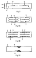
- Fig. 2 is a schematic view of the vessel 2 of Fig. 1 as viewed in the propagation direction of the beam 15 (i.e., from top in Fig. 1 ).
- Fig. 2 One spatio-temporal pattern along which the beam 15 may be moved in an exemplary embodiment is illustrated in Fig. 2 .
- the beam 15 is scanned essentially along the longitudinal direction of the vessel 2.
- the scanning of the beam 15 is performed such that power is supplied at a first plurality of positions 21 in a time-sequential manner, the beam 15 being displaced from one of the first positions 21 to another one of the first positions 21 in a first direction 23.
- the scanning of the beam 15 is further performed such that power is supplied at a plurality of second positions 22 in a time-sequential manner, the beam 15 being displaced from one of the second positions 22 to another one of the second positions 22 in a second direction 24 which is essentially opposite to the first direction 23.
- a scanning pattern as indicated in Fig. 2 may be implemented, for example, by controlling the actuator 14 such that the mirror 13 is tilted in one direction in a step-wise fashion until the beam 15 passes through the rightmost position of the first positions 21 in Fig. 2 ; thereafter, controlling the source 12 such that the output power is essentially zero while controlling the actuator 14 such that the mirror 13 continues to be tilted in the one direction; thereafter, controlling the source 12 such that it again has a finite energy output and controlling the actuator 14 such that the mirror 13 is tilted in another direction, opposite to the one direction, in a step-wise fashion until the beam 15 passes through the leftmost position of the second positions 22 in Fig. 2 ; thereafter, controlling the source 12 such that the output power is essentially zero while controlling the actuator 14 such that the mirror 13 continues to be tilted in the other direction. Thereafter, the scanning cycle may be repeated.
- first positions 21 and the second positions 22 are shown to be pair-wise spaced from each other in Fig. 2 , the first positions 21 and the second positions 22 may also be arranged so as to respectively form continuous line segments.
- Fig. 3A is a schematic diagram illustrating a fluid flow established in the vessel 2 when the beam 15 is scanned along the vessel 2 in, for example, the scanning pattern illustrated in Fig. 2 .
- scanning the beam 15 through the first positions 21 has the effect of locally driving the PCR buffer solution, the velocity at the first positions 21 being generally directed opposite to the first scan direction 23.
- the flow velocity has a magnitude which is controllable by controlling the rate at which the beam 15 passes through each one of the first positions 21 and the temperature increase that is respectively attained at the first positions 21 upon passage of the beam 15.
- PCR buffer solution As the PCR buffer solution is driven only over a finite length along the longitudinal direction of the vessel 2, return flows along the vessel side walls emerge, giving rise to circulating flows 31 and 32 within the vessel. Similarly, scanning the beam 15 through the second positions 22 has the effect of locally driving the PCR buffer solution, the velocity at the second positions 22 being generally directed opposite to the second scan direction 24 and having a magnitude which is controllable by controlling the rate at which the beam 15 passes through each one of the second positions 22 and the temperature increase that is respectively attained at the second positions 22 upon passage of the beam 15. As the PCR buffer solution is driven only over a finite length along the longitudinal direction of the vessel 2, circulating flows 33 and 34 emerge.
- the rotation direction of the circulating flow 31 is opposite to the rotation direction of the circulating flow 33 adjacent to the circulating flow 31 in the longitudinal direction of the vessel 2.
- the rotation direction of the circulating flow 32 is opposite to the rotation direction of the circulating flow 34 adjacent to the circulating flow 32 in the longitudinal direction of the vessel 2.
- Fig. 3B is a schematic diagram illustrating regions of different temperatures established in the vessel 2 when the beam 15 is scanned along the vessel 2 in, for example, the scanning pattern illustrated in Fig. 2 .
- the PCR buffer solution in a first region 35 located in proximity to the first positions 21 is heated to a temperature that is higher than a temperature in second regions 36 that are offset relative to the first region 35 in the transverse direction of the vessel 2.
- the first region 35 and the second regions 36 will typically extend through the vessel in the direction normal to the image plane of Fig. 2 .
- the PCR buffer solution in a first region 37 located in proximity to the second positions 22 is heated to a temperature that is higher than a temperature in second regions 38 that are offset relative to the first region 37 in the transverse direction of the vessel 2.
- the first region 37 and the second regions 38 will typically extend through the vessel in the direction normal to the image plane of Fig. 2 .
- the temperature adjusting means and the source 12 supplying heating power to the PCR buffer solution are configured such that in the first regions 35 and 37 the PCR buffer solution has a temperature at which a denaturation of the nucleic acid sequence(s) which is or are to be replicated takes place, and in the second regions 36 and 38 the PCR buffer solution has a temperature at which an annealing and elongation step of a PCR take place.
- Fig. 3A in combination with Fig. 3B illustrate that, by supplying energy to the PCR buffer solution 3 in the vessel 2 at a plurality of positions 21 and 22, respectively, circulating fluid flows 31-34 are established.
- PCR buffer solution circulating in the flow paths 31-34 experiences a temperature cycling, as the flow paths 31-34 traverse both a first region 35 or 37, respectively, having an elevated temperature and a second region 36 or 38, respectively, having a lower temperature. Thereby, the PCR temperature cycling is implemented.
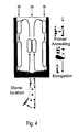
- Fig. 4 is a schematic diagram illustrating the temperature cycling in the vessel 2. Only one half of the vessel 2 is illustrated in Fig. 4 . As schematically illustrated in Fig. 4 , in the first region 35 within the vessel the PCR buffer solution has a temperature at which a denaturation step of a PCR takes place. In the second regions 36, the PCR buffer solution has a temperature at which annealing and elongation steps of a PCR take place.
- thermophoretic drift will be established between the regions in which the PCR buffer solution has different temperature.
- the magnitude of the thermophoretic drift of a molecule or particle in the PCR buffer solution is characterized by the thermodiffusion coefficient D T of the respective molecule or particle comprised by the PCR buffer solution.
- thermophoretic drift For the temperature variation established by locally supplying energy to a plurality of positions disposed along the longitudinal direction of the vessel 2, the thermophoretic drift will be directed essentially in the transverse direction of the vessel 2. Referring to Fig. 3B , a thermophoretic drift will be established between the first region 35 and the second regions 36, and a thermophoretic drift will be established between the first region 37 and the second regions 38, respectively.
- thermodiffusion coefficient is frequently found to be positive.
- the thermophoretic drift is then directed from the first region 35 or 37 having a higher temperature to the second regions 36 or 38, respectively, having a lower temperature.
- thermodiffusion in the transverse direction of the vessel 2 and the bi-directional flow along flow paths 31-34 gives rise to a local increase in concentration of molecules or particles in accumulation regions 39, which are located in between the circulating flows 31 and 33 and in between the circulating flows 32 and 34.
- the regions 39 in which the concentration of molecules or particles is locally increased are schematically illustrated in Fig. 3C .
- Fig. 5 is a schematic diagram illustrating the interplay of thermodiffusion and circulating fluid flows established by locally supplying energy at plural positions disposed along the longitudinal direction of the vessel 2. Only one half of the vessel 2 is illustrated in Fig. 5 .
- thermophoretic drift is indicated by arrows.
- the greyscale background illustrates the temperature variation within the vessel, with darker portions indicating higher temperatures.
- the thermophoretic drift is directed from the plane along which the beam 15 is scanned toward the lateral walls of the vessel, in a direction transverse to the plane along which the beam 15 is scanned.
- thermophoretic drift indicated in graph 41 indicates a concentration of a molecule that exhibits thermophoretic drift in a greyscale representation.
- darker colours indicate a higher concentration, and lighter colours represent a lower concentration.
- the combination of the thermophoretic drift indicated in graph 41 and the circulating fluid flows indicated in graph 42 lead to a local increase in concentration of the respective molecule or particle in a region 39 in the vessel 2, which is disposed at a central position of the vessel, i.e., spaced from the ends of the vessel 2.
- thermophoretic drift and a circulating fluid flow gives rise to a local increase in concentration in an accumulation region 39 within the vessel
- both the fluid flow circulating within the vessel and diffusion will allow molecules or particles accumulated in the accumulation region 39 to leave the accumulation region 39 at least for some time before being transported back into the accumulation region 39. Therefore, the PCR may be performed even when the concentration of the replicated nucleic acid sequence(s) exhibits pronounced variations in concentration.
- the mechanism described with reference to Figs. 3B, 3C and 5 which transports molecules or particles toward specific accumulation regions 39, is counterbalanced by diffusion.
- the local increase in concentration is controllable by adjusting the flow velocity of the fluid flows 31-34 circulating within the vessel 2.
- the local increase in concentration in the accumulation region i.e., the quotient c acc /c 0
- the local increase in concentration may be controlled by controlling the velocity of the fluid flows circulating within the vessel.
- the velocity v c-max at which the right-hand side of Equation (9) becomes maximum is a function of D/a.
- the local increase in concentration in the accumulation region may be made more pronounced for one type of molecule, complex or particle than for other types of molecules, complexes or particles by adjusting the velocity v c of the fluid flows circulating within the vessel.
- a velocity of the fluid flow may be adjusted by controlling the spatio-temporal pattern in which heating power is supplied to the PCR buffer solution.
- a maximum flow velocity of the PCR buffer solution within the vessel may be adjusted by controlling the output power of the source 12 of electromagnetic radiation and/or by adjusting the rate f at which power is respectively supplied at the plurality of positions and/or by controlling the spatio-temporal heating pattern.
- the apparatus and method according to various embodiments allow the local increase in concentration of a molecule, complex or particle to be controlled via the spatio-temporal pattern according to which heating power is supplied to the PCR buffer solution. Further, the accumulation may be made more pronounced for one type of molecule, complex or particle than for other types of molecules, complexes or particles by controlling the spatio-temporal heating pattern.
- Fig. 6 is a graph illustrating, for three different types of molecules, the normalized increase in concentration c acc /c 0 as a function of the maximum velocity v c of the fluid flow circulating within an elongated vessel having a rectangular cross section.
- the results of two-dimensional numerical simulations are shown in solid lines, while the right-hand side of Equation (9) is respectively shown in broken lines. The results have been obtained for a fluid flow having a transverse width of 50 ⁇ m.
- a maximum enhancement of the concentration is expected for v c-max ⁇ 4,92 ⁇ m/s indicated at 57.
- a maximum enhancement of the concentration is expected for v c-max ⁇ 39,5 ⁇ m/s.
- a pronounced local increase in concentration can be attained for the 100mer dsDNA in an accumulation region, while the local increases in concentration are less pronounced for the 22mer ssDNA and single nucleotides.
- Fig. 7 is a schematic view of an apparatus 70 according to another embodiment.
- the inset 60 shows an enlarged cross-sectional view taken in a plane perpendicular to a longitudinal axis of a vessel.
- the vessel 2 is configured as a silica capillary having a square inner diameter.
- An inner width of the vessel 2 may be, for example, 50 ⁇ m.
- the vessel 2 is supported on a silicon wafer 61, which allows the output beam 15 of a source 12 of electromagnetic radiation to pass therethrough.
- Immersion oil 63 is provided in the space between the silicon wafer 61 and a coverslip 62.
- the vessel 2 may be releasably supported on the silicon wafer 61, so that the vessel 2 can be exchanged when required.
- the apparatus 70 further comprises the source 12 of electromagnetic radiation, which in this case is configured as an IR laser having an output wavelength of 1940 nm, a pair of x-y-mirrors 71 that allow the output beam 15 of the source 12 of electromagnetic radiation to be deflected, a laser lens 72 for focussing the beam 15 in the capillary and a heat bath 73 for suppressing thermal expansion of the x-y-mirrors 71 and/or laser lens 72.
- a laser control 75 allows the laser output power to be controlled, e.g., by switching the laser output on and off.
- An x-y-mirror control 74 controls the deflection of the beam 15 and, thereby, the position at which the beam 15 passes through the vessel 2.
- the source 12 of electromagnetic radiation in combination with the scanning arrangement implemented by the x-y-mirrors 71 make it possible to locally supply heating power to a solution within the vessel at a plurality of positions in a time-varying manner.
- the time-averaged output power of the IR-laser is adjusted so as to attain a desired temperature difference between different regions within the vessel 2.
- the apparatus 70 further includes a temperature adjusting means which allows an offset temperature of the solution within the vessel 2 to be adjusted.
- the temperature adjusting means comprises Peltier elements 78 which are controlled by a Peltier control 79.
- the silicon wafer 61 is positioned in thermal contact with the Peltier elements 78, and heat is also transferred from the silicon wafer 61 to the immersion oil 63 which comes into contact with the longitudinal side walls of the vessel 2.
- an offset temperature may be adjusted in the solution within the vessel. Heat may be transferred to the vessel 2 via the Silicon wafer 61 or the immersion oil 63.
- the temperature adjusting means in combination with the local heating provided by scanning the beam 15 through the vessel 2 allows a spatially varying temperature to be established within the vessel such that, in a first region within the vessel, the solution has a temperature at which a denaturation step of a PCR takes place, and in a second region within the vessel, the solution has a temperature at which an annealing and elongation step, respectively, of a PCR take place.
- a heat bath 76 reduces thermal expansion of the microscopy stage due to, e.g., laser absorption.
- the heat bath may also allow the peltier elements to hold the probe temperature at a constant level over an extended period of time.
- the apparatus 70 further comprises optical components that allow progress of a PCR to be directly monitored, for example, in a real-time PCR.
- a fluorescence microscope 82 comprises a LED 83, e.g., a cyan LED, for illumination. The LED 83 is controlled by a LED control 84.
- Optical components such as air optics 81 for focussing a signal from the solution within the vessel, a semitransparent mirror 85 and suitable filters 86, like an emission-/absorption and IR filter, allow the solution within the vessel 2 to be imaged.
- a CCD camera 87 provides captured image data to an image capture tool 89. The CCD camera 87 is triggered by a CCD-camera trigger 88.
- One or several of the x-y-mirror control 74, the laser control 75, the Peltier control 79, the LED control 84, the CCD-camera trigger 88 and the image capture tool 89 may be implemented by software, hardware or a combination of both in a computer 17.
- the computer 17 may be embedded in the apparatus 70.
- the apparatus 70 further comprises a pump 91.
- the pump 91 allows a net flow of PCR solution to be established through the vessel 2.
- one or usually at least two fluid flows circulating within the vessel 2 may be established in the manner described with reference to Figs. 1-6 , i.e., by scanning the output beam 15 of the IR laser through a plurality of positions.
- the level of control provided when the fluid flows are driven by locally heating the solution within the vessel 2 in a time-varying manner allows the various processes described with reference to Figs. 1-6 , including a temperature cycling realized by the fluid flows circulating within the vessel and a local accumulation of specific molecules, complexes or particles, to be realized within the vessel 2.
- such processes may be monitored using the fluorescence microscope 82.
- Fig. 8 is a greyscale representation of a velocity field established in the vessel 2 using the IR laser and scanning components of the apparatus of Fig. 7 .
- a borosilicate capillary having a square cross section of 100 ⁇ m ⁇ 50 ⁇ m and a length of 1800 ⁇ m has been sealed on both ends with a reservoir of paraffin oil.
- the solution in the capillary has been a commercial FastPCR master mix (Qiagen).
- the laser beam has been scanned along the capillary longitudinal axis as described with reference to Fig. 2 .
- To estimate the fluid flow velocity 1 ⁇ m fluorescent beads (F8888, Invitrogen) were imaged in the initial 5 seconds after the laser had been switched on.
- the velocity field is shown in Fig. 8 in a greyscale representation.
- the flow direction is respectively indicated by arrows.
- a maximum flow velocity of approximately 70 ⁇ m/s has been recorded.
- Fig. 9 shows molecular pathways in the silica capillary which result from the velocity field of Fig. 8 and thermophoretic drift for 143mer DNA.
- the thermophoretic drift has been determined based on temperature imaging performed with the dye BCECF ((2',7'-bis-(2-carboxyehtyl)-5-(and-6)-carboxyfluorescein, Fermentas).
- BCECF dye that is used to Fig. 9
- there are molecular pathways which terminate at the lateral walls of the capillary in a centre region of the capillary. This leads to a local increase in concentration of the 143mer DNA in an accumulation region indicated at 39.
- Fig. 10A shows a graph illustrating the concentration of a 143mer DNA as seen in fluorescence images at three different times, using the same setting as for Figs. 8 and 9 . Only one half of the capillary is shown in Fig. 10A , the lower end of the fluorescence images corresponding to a central portion of the capillary.
- Fig. 10B shows a graph illustrating the measured centre concentration of the 143mer DNA and results of finite element simulations. A significant increase in concentration of the 143mer DNA has been observed over a time of a few hundred seconds.
- Fig. 11 shows a graph illustrating the fluorescence signal obtained when heating power is supplied so as to establish conditions in which both a local increase in concentration and a PCR are attained in the reaction vessel. Only data obtained from one half of the capillary is shown in Fig. 11 , the lower end of the fluorescence images corresponding to a central portion of the capillary.
- the reaction vessel is identical to the one in which the measurements explained with reference to Figs. 8-10 have been performed, i.e., a silica capillary having an inner diameter of 100 ⁇ m ⁇ 50 ⁇ m and a length of 1800 ⁇ m.
- the vessel contains a solution which consists of 10 ⁇ l FastPCR master mix (Qiagen), 1 ⁇ l of a 1 nM diluted 143mer template, 2 ⁇ 1 ⁇ l primer with a final concentration of 500nM , 1 ⁇ l 10 x SYBR Green I (Molecular Probes, Eugene), 1 ⁇ l 60 mg/ml BSA (biotin free, Roth) to prevent polymerase denaturation at the capillary surface and 6 ⁇ l ultra pure water.
- An IR laser beam has been scanned along two line segments in a scanning pattern as shown in Fig. 2 .
- the scan parameters have been set so as to establish the velocity field shown in Fig. 8 with a maximum flow velocity of approximately 70 ⁇ m/s.
- the laser power and a temperature offset have been set so that the solution has a temperature of 86°C in a first region within the capillary (where laser heating takes place) and a temperature of 59°C in second regions offset relative to the first region in the transverse direction of the capillary.
- the fluorescence data has been acquired after times of 1 min, 4 min, 8 min, 12 min and 14 min.
- the fluorescence signal exhibits a pronounced increase over time.
- the signal varies strongly as a function of location, indicating an accumulation in a centre portion of the capillary.
- c T (t) describes the accumulation as a function of time in the absence of a PCR, as shown in Fig. 10B
- ⁇ d is the doubling time
- c max is the maximal concentration to be achieved.
- Equation (10) By fitting Equation (10) to the measured fluorescence data, a doubling time of ⁇ d ⁇ 74 s is obtained. This time is comparable to an average cycling time for the solution in the circulating fluid flows established in the capillary, supporting that the temperature cycling is effected by the circulating fluid flows.
- the two values are comparable within the given errors.
- the measurement has been repeated with a solution which does not comprise the 143mer DNA template. No significant fluorescence signal has been found over a time of 14 min.
- thermodiffusion characteristics of the molecules accumulated in the capillary centre after the PCR have been measured using the technique described in WO 2009/141390 A1 .
- the signal has been compared to the signal obtained with a 143mer DNA replicated in a conventional thermocycler. Good agreement has been obtained, supporting that the product accumulated in the capillary centre is the replicated 143mer DNA.
- FIG. 12-15 yet another embodiment of the invention will be described.
- an apparatus configured for example as explained with reference to Figs. 1-6 or with reference to Fig. 7 may be utilized for applications such as aptamer synthesis, as already detailed above.
- local heating of the solution within the vessel may be performed such that,
- Fig. 12 is a schematic view of an elongated vessel 2 having a transverse inner width indicated at 5.
- the vessel 2 contains a PCR buffer solution comprising one or more nucleic acid sequence(s), a nucleic acid polymerase, NTPs, a first primer and a second primer.
- the nucleic acid sequences are ssDNA or ssRNA sequences which comprise random sequences comprising respectively at their 5' and 3' ends fixed sequences for PCR amplification.
- the PCR solution may be a mutagenic PCR solution and may additionally comprise a plurality of target sequences immobilised on a carrier.
- the PCR solution may further comprise an intercalating dye.
- Heating power is supplied to the solution within the vessel 2 at a plurality of positions 101-104 in a time-varying manner, so that the position(s) at which heating power is supplied to the solution varies as a function of time.
- heating power may be supplied in a time-varying manner by temporal scanning of, e.g., an IR laser beam.
- an amount of energy respectively supplied at the various positions may be set so as to vary as a function of position.
- flow velocities of fluid flows circulating within the vessel and temperature gradients established in the transverse direction of the vessel can be controlled separately in different portions along the longitudinal direction of the vessel.
- heating power is supplied to a plurality of positions 101 and 102 such that the position at which the solution is heated moves in a first direction 23.
- the amount of energy respectively supplied at the positions 101 that are further away from a vessel centre portion is respectively greater than an amount of energy respectively supplied at the positions 102 that are located closer to the vessel centre portion.
- a heating pattern as illustrated in the left-hand side of Fig. 12 may be realized by scanning a laser beam in the first direction 23 along the vessel longitudinal direction while controlling the laser output power.
- heating power is supplied to a plurality of positions 103 and 104 such that the position at which the solution is heated moves in a second direction 24.
- a heating pattern as illustrated in the right-hand side of Fig. 12 may be realized by scanning a laser beam in the second direction 24 along the vessel longitudinal direction while controlling the laser output power.
- the laser beam may be scanned over the positions 101 and 102 and over the positions 104 and 103 in a time-sequential manner, the scanning being periodically repeated.
- Fig. 13 is a schematic view illustrating fluid flows established in the vessel when a heating pattern as shown in Fig. 12 is implemented, in which the energy supplied to the solution is varied as a function of position.
- temperature is schematically indicated in greyscale, wherein darker colour corresponds to higher temperature.
- Fluid flows are schematically indicated by arrows within the vessel.
- Regions having different temperature variations are established in the vessel 2.
- Figs. 14A and 14B schematically illustrates a temperature profile 123 indicating the temperature of the solution as a function of transverse position in the portion 111, as established at the longitudinal position 121 indicated in Fig. 13.
- Fig. 14B schematically illustrates a temperature profile 123 indicating the temperature of the solution as a function of transverse position in the portion 112, as taken at the longitudinal position 122 indicated in Fig. 13 .
- the temperature profile 123 shows a stronger variation in temperature than the temperature profile 124.
- the local heating in accordance with a spatio-temporal pattern as indicated in Fig. 12 gives rise to fluid flows 114, 115, 116 and 117 circulating within the vessel 2.
- the counter-rotating fluid flows in the portion 112 in combination with the thermal gradient in the transverse direction of the vessel 2 give rise to a local increase in concentration of molecules, complexes or particles comprised by the solution in an accumulation region 119, which is spaced from the ends of the vessel 2.
- the amount of local concentration enhancement in the accumulation region 119 depends on the characteristics of the respective molecule, complex or particle, in particular on its diffusion coefficient.
- the vessel 2 may be open at its ends, and a net flow 130 of solution may be driven through the vessel 2.
- the net flow 130 may be driven, for example, by using micropumps.
- a power source which locally supplies heating power to the solution and a temperature adjusting means are controlled such that a spatial temperature variation is established in portions 111 and 113 that allows a PCR to take place.
- the power source is further controlled such that the maximum flow velocities in the circulating fluid flows 115 and 116 are set based on a diffusion coefficient of a molecule, complex or particle, for which a strong accumulation is desired.
- the maximum flow velocities in the circulating fluid flows 115 and 116 may be set based on the quotient of the diffusion coefficient of a molecule, complex or particle, for which a strong accumulation is desired, and the transverse width "a" of at least one fluid flow circulating within the vessel 2.
- the maximum flow velocities in the circulating fluid flows 115 and 116 may be set such that 3,99 ⁇ (D/a) ⁇ v c ⁇ 5,39 ⁇ (D/a), in particular such that 4,45 ⁇ (D/a) ⁇ v c ⁇ 4,92 ⁇ (D/a), in particular such that v c ⁇ 4,69 ⁇ (D/a), where D denotes the diffusion coefficient of the molecule, complex or particle for which a high local concentration in the accumulation area 119 is desired, and where v c denotes a vessel-averaged maximum velocity.
- the vessel-averaged maximum velocity may be approximated to be 2/3 of the actual maximum velocity within the vessel, which may be adjusted via adjusting the manner in which heating power is locally supplied to the solution.
- the transverse width of the circulating fluid flows may essentially correspond to a distance between the positions 102, 103 and the lateral walls of the vessel 2 offset thereto in a direction perpendicular to the beam of electromagnetic radiation.
- a method of synthesising aptamers will be described, in which a temperature distribution and velocity field as exemplarily shown in Figs. 13 and 14 may be utilized.
- the vessel 2 contains a PCR buffer solution comprising nucleic acid sequences, a nucleic acid polymerase, NTPs, a first primer and a second primer.
- the nucleic acid sequences are ssDNA or ssRNA sequences which comprise random sequences comprising respectively at their 5' and 3' ends fixed sequences for PCR amplification.
- the PCR solution is a mutagenic PCR solution and additionally comprises a plurality of target sequences immobilised on a carrier.
- a relation between the first primer and the second primer is between 1:10 and 1:30. This allows an asynchronous PCR to be performed, in which the formation of dsDNA or dsRNA is suppressed.
- target molecules are antibodies, labelled nanoparticles etc.
- Heating power is supplied to the PCR buffer solution within the vessel, for example using IR laser scanning, such that in portions 111 and 113 a temperature difference of at least 25K, in particular of approximately 35K, is established between the solution at the lateral centre and the solution at the lateral side walls of the vessel.
- the heating power supplied at the plurality of positions 101 and 104 and a temperature adjusting means is controlled such that in portions 111 and 113 the solution in a centre region surrounding positions 101 and 104 has a temperature of approximately 90°C, and the solution has a temperature of approximately 55°C in proximity to the lateral walls of the vessel. Temperature cycling between 90°C and 55°C is achieved by the circulating fluid flows 114 and 117.
- heating power is supplied such that a peak temperature of the solution within the portion 112 is smaller than a peak temperature of the solution within the portions 111 and 113, and is adjusted such that, if a complex is formed between the amplified nucleic acid sequence and a specific target sequence immobilised on the carrier, a dissociation rate of the complex is low at the peak temperature within the portion 112. Further, a maximum flow velocity of the circulating fluid flows 115 and 116 within the portion 112 is adjusted, e.g. by controlling the IR laser scanning, such that a pronounced concentration increase of the carrier with the complex between the amplified nucleic acid sequence and the specific target sequence immobilised on the carrier is attained in the accumulation regions 119.
- ssDNA or ssRNA that has not formed a complex with the specific target exhibits less pronounced variations in concentration and is more likely to diffuse from portion 112 to one of portion 111 and 113, where it will be mutated and replicated.
- Mutated ssDNA or ssRNA formed in the portion 111 and 113 may move from the portion 111 or 113 to the centre portion 112, for example due to drift or diffusion.
- the suitably mutated ssDNA or ssRNA may form a complex with the target, depending on its nucleic acid sequence and accumulates in the accumulation region.
- a net flow 120 of the solution through the vessel 2 is established, in order to supply new NTPs and nucleic acid polymerase to portions 111 and 113, so that the PCR may be performed over extended periods of time.
- a velocity of the net flow 120 is set to be smaller than the maximum velocity in the fluid flows 115-117.
- the net flow 120 may have a velocity of less than 1 ⁇ m/s.
- ssDNA or ssRNA and the specific target immobilised on the carrier will be accumulated in the accumulation region 119.
- non-binding ss nucleic acid molecules may be modified so as to enable their binding to the specific target molecule.
- Said ss nucleic acid may be created, for example by a combinatorial library in relation to a not identified biological molecule.
- the ssDNA or ssRNA that forms the complex with the specific target may be extracted from the accumulation region 119 and may be subject to further processing.
- the further processing may include separating the ssDNA or ssRNA from the target, cloning and DNA or RNA sequencing.
- Fig. 15 is a schematic illustration of the above-described process. While the process will be explained for ssDNA with reference to Fig. 15 for illustration, it is to be understood that the process may also be implemented with ssRNA.
- a pool of ssDNA or ssRNA is indicated at 131.
- the pool comprises ssDNA sequences which comprise random sequences comprising respectively at their 5' and 3' ends 132 or 133 fixed sequences for PCR amplification.
- the solution 134 includes targets, carrier molecules on which the targets are immobilised, and the pool of ssDNA.
- a ssDNA 135 that can form a complex with the targets is schematically illustrated to have a triangular shape.
- ssDNA may or may form a complex with the target, as indicated at 141.
- the complex between the ssDNA and the target immobilised on the carrier molecule will be accumulated, as indicated at 145.
- the complexes may be extracted from the vessel, for example by using electrophoresis, and may be subject to further processing, as indicated at 146.
- the further processing may include separating the ssDNA or ssRNA from the carrier, cloning and DNA or RNA sequencing.
- the ssDNA may move to portions of the vessel in which an aPCR is performed, as indicated at 142.
- the ssDNA may diffuse into a portion of the vessel having higher peak temperatures, in which an aPCR is performed.
- the ssDNA may be replicated, as indicated at 143.
- a ssDNA molecule may be obtained that is able to bind to the target on the carrier thus forming a complex.
- the replicated and/or mutated ssDNA may move back from the aPCR portion to the selection portion of the vessel, as indicated at 144 depending on its ability to form a complex with the target.
- binding molecules to virtually any target may conveniently be created in large amounts to be used for therapeutic or diagnostic purposes. Moreover, that reaction may also be used for diagnostic purposes.
- On the basis of the binding of a selected ssDNA to a specific target information about a disease state, for example characterized by the up-regulation of receptors, may be obtained.
Landscapes
- Chemical & Material Sciences (AREA)
- Health & Medical Sciences (AREA)
- Chemical Kinetics & Catalysis (AREA)
- General Health & Medical Sciences (AREA)
- Life Sciences & Earth Sciences (AREA)
- Analytical Chemistry (AREA)
- Clinical Laboratory Science (AREA)
- Organic Chemistry (AREA)
- Hematology (AREA)
- Dispersion Chemistry (AREA)
- Biochemistry (AREA)
- Molecular Biology (AREA)
- Zoology (AREA)
- Proteomics, Peptides & Aminoacids (AREA)
- Engineering & Computer Science (AREA)
- Wood Science & Technology (AREA)
- Biophysics (AREA)
- Microbiology (AREA)
- Immunology (AREA)
- Biotechnology (AREA)
- Physics & Mathematics (AREA)
- Bioinformatics & Cheminformatics (AREA)
- General Engineering & Computer Science (AREA)
- Genetics & Genomics (AREA)
- Measuring Or Testing Involving Enzymes Or Micro-Organisms (AREA)
- Preparation Of Compounds By Using Micro-Organisms (AREA)
- Apparatus Associated With Microorganisms And Enzymes (AREA)
Priority Applications (3)
| Application Number | Priority Date | Filing Date | Title |
|---|---|---|---|
| EP10001234A EP2353716A1 (fr) | 2010-02-05 | 2010-02-05 | Procédé et appareil pour amplifier les séquences d'acide nucléique |
| EP11153165.3A EP2353720A3 (fr) | 2010-02-05 | 2011-02-03 | Procédé et appareil pour amplifier les séquences d'acide nucléique |
| US13/021,379 US20110195458A1 (en) | 2010-02-05 | 2011-02-04 | Method and Apparatus for Amplifying Nucleic Acid Sequences |
Applications Claiming Priority (1)
| Application Number | Priority Date | Filing Date | Title |
|---|---|---|---|
| EP10001234A EP2353716A1 (fr) | 2010-02-05 | 2010-02-05 | Procédé et appareil pour amplifier les séquences d'acide nucléique |
Publications (1)
| Publication Number | Publication Date |
|---|---|
| EP2353716A1 true EP2353716A1 (fr) | 2011-08-10 |
Family
ID=42312831
Family Applications (2)
| Application Number | Title | Priority Date | Filing Date |
|---|---|---|---|
| EP10001234A Withdrawn EP2353716A1 (fr) | 2010-02-05 | 2010-02-05 | Procédé et appareil pour amplifier les séquences d'acide nucléique |
| EP11153165.3A Withdrawn EP2353720A3 (fr) | 2010-02-05 | 2011-02-03 | Procédé et appareil pour amplifier les séquences d'acide nucléique |
Family Applications After (1)
| Application Number | Title | Priority Date | Filing Date |
|---|---|---|---|
| EP11153165.3A Withdrawn EP2353720A3 (fr) | 2010-02-05 | 2011-02-03 | Procédé et appareil pour amplifier les séquences d'acide nucléique |
Country Status (2)
| Country | Link |
|---|---|
| US (1) | US20110195458A1 (fr) |
| EP (2) | EP2353716A1 (fr) |
Families Citing this family (3)
| Publication number | Priority date | Publication date | Assignee | Title |
|---|---|---|---|---|
| US20170282178A1 (en) * | 2016-03-30 | 2017-10-05 | Credo Biomedical Pte Ltd. | Portable qpcr and qrt-pcr apparatus |
| EP3489732A1 (fr) * | 2017-11-24 | 2019-05-29 | Max-Planck-Gesellschaft zur Förderung der Wissenschaften e.V. | Appareil et procédé d'imagerie et d'exécution simultanées d'un flux hydrodynamique dirigé sans contact |
| CN116814864B (zh) * | 2023-08-30 | 2023-11-24 | 深圳赛陆医疗科技有限公司 | 基因测序中芯片转移控制方法及装置、设备、系统及介质 |
Citations (4)
| Publication number | Priority date | Publication date | Assignee | Title |
|---|---|---|---|---|
| US20020127152A1 (en) | 2001-03-09 | 2002-09-12 | The Regents Of The University Of California | Convectively driven PCR thermal-cycling |
| US20040191830A1 (en) | 2001-10-30 | 2004-09-30 | Hwang Hyun Jin | Method and apparatus for amplification of nucleic acid sequences using immobilized DNA polymerase |
| US20060216725A1 (en) | 2004-09-15 | 2006-09-28 | You-Seop Lee | Polymer chain reaction apparatus using marangoni convection and polymer chain reaction method using the same |
| EP1974814A1 (fr) | 2007-03-23 | 2008-10-01 | Koninklijke Philips Electronics N.V. | Dispositif micro-fluidique basé selon les principes de matrice active |
Family Cites Families (4)
| Publication number | Priority date | Publication date | Assignee | Title |
|---|---|---|---|---|
| US4683195A (en) | 1986-01-30 | 1987-07-28 | Cetus Corporation | Process for amplifying, detecting, and/or-cloning nucleic acid sequences |
| US4683202A (en) | 1985-03-28 | 1987-07-28 | Cetus Corporation | Process for amplifying nucleic acid sequences |
| DE19717085C2 (de) | 1997-04-23 | 1999-06-17 | Bruker Daltonik Gmbh | Verfahren und Geräte für extrem schnelle DNA-Vervielfachung durch Polymerase-Kettenreaktionen (PCR) |
| WO2009141390A1 (fr) | 2008-05-20 | 2009-11-26 | Ludwig-Maximilians-Universität München | Procédé et dispositif pour l'analyse de particules à l'aide de la thermophorèse |
-
2010
- 2010-02-05 EP EP10001234A patent/EP2353716A1/fr not_active Withdrawn
-
2011
- 2011-02-03 EP EP11153165.3A patent/EP2353720A3/fr not_active Withdrawn
- 2011-02-04 US US13/021,379 patent/US20110195458A1/en not_active Abandoned
Patent Citations (4)
| Publication number | Priority date | Publication date | Assignee | Title |
|---|---|---|---|---|
| US20020127152A1 (en) | 2001-03-09 | 2002-09-12 | The Regents Of The University Of California | Convectively driven PCR thermal-cycling |
| US20040191830A1 (en) | 2001-10-30 | 2004-09-30 | Hwang Hyun Jin | Method and apparatus for amplification of nucleic acid sequences using immobilized DNA polymerase |
| US20060216725A1 (en) | 2004-09-15 | 2006-09-28 | You-Seop Lee | Polymer chain reaction apparatus using marangoni convection and polymer chain reaction method using the same |
| EP1974814A1 (fr) | 2007-03-23 | 2008-10-01 | Koninklijke Philips Electronics N.V. | Dispositif micro-fluidique basé selon les principes de matrice active |
Non-Patent Citations (8)
| Title |
|---|
| A. S. BASU; Y. B. GIANCHANDANI: "J. Micromech. Microeng", vol. 18, 1 November 2008, IOP PUBLISHING, article "Virtual microfluidic traps, filters, channels and pumps using Marangoni flows" |
| AMAR S BASU ET AL: "Virtual microfluidic traps, filters, channels and pumps using Marangoni flows", JOURNAL OF MICROMECHANICS & MICROENGINEERING, INSTITUTE OF PHYSICS PUBLISHING, BRISTOL, GB LNKD- DOI:10.1088/0960-1317/18/11/115031, vol. 18, no. 11, 1 November 2008 (2008-11-01), pages 115031, XP020145049, ISSN: 0960-1317 * |
| EMIR VELA ET AL.: "IEEE/RSJ International Conference on Intelligent Robots and Systems", 2008, IEEE, PISCATAWAY, article "Non-contact mesoscale manipulation using laser induced convection flows" |
| EMIR VELA ET AL: "Non-contact mesoscale manipulation using laser induced convection flows", INTELLIGENT ROBOTS AND SYSTEMS, 2008. IROS 2008. IEEE/RSJ INTERNATIONAL CONFERENCE ON, IEEE, PISCATAWAY, NJ, USA, 22 September 2008 (2008-09-22), pages 913 - 918, XP031348450, ISBN: 978-1-4244-2057-5 * |
| F. M. WEINERT; D. BRAUN: "An Optical Conveyor for Molecules", NANO LETT., vol. 9, no. 12, 2009, pages 4264 - 4267 |
| F. M. WEINERT; D. BRAUN: "Optically driven fluid flow along arbitrary microscale patterns using thermoviscous expansion", J. APPL. PHYS., vol. 104, 2008, XP012116563, DOI: doi:10.1063/1.3026526 |
| P. BAASKE ET AL.: "Extreme accumulation of nucleotides in simulated hydrothermal pore systems", PNAS, vol. 104, no. 22, 2007, pages 9346 |
| WEINERT FRANZ ET AL: "Optically driven fluid flow along arbitrary microscale patterns using thermoviscous expansion", JOURNAL OF APPLIED PHYSICS, AMERICAN INSTITUTE OF PHYSICS. NEW YORK, US LNKD- DOI:10.1063/1.3026526, vol. 104, no. 10, 25 November 2008 (2008-11-25), pages 104701 - 104701, XP012116563, ISSN: 0021-8979 * |
Also Published As
| Publication number | Publication date |
|---|---|
| EP2353720A3 (fr) | 2014-03-12 |
| EP2353720A2 (fr) | 2011-08-10 |
| US20110195458A1 (en) | 2011-08-11 |
Similar Documents
| Publication | Publication Date | Title |
|---|---|---|
| US7927797B2 (en) | Nucleic acid amplification with continuous flow emulsion | |
| US7579172B2 (en) | Method and apparatus for amplifying nucleic acids | |
| US10052632B2 (en) | Channels with cross-sectional thermal gradients | |
| JP6609544B2 (ja) | Dnaを取り扱うためのマイクロ流体法 | |
| RU2603253C2 (ru) | Способ амплификации нуклеиновых кислот | |
| CN102076869A (zh) | 使用多个温度区域的核酸扩增 | |
| US20140272996A1 (en) | Droplet generator with collection tube | |
| CN111979092A (zh) | 蜂窝管 | |
| US20230008992A1 (en) | Devices for generating pre-templated instant partitions | |
| EP3296386B1 (fr) | Tube de réaction d'amplification d'acide nucléique capable de réguler la trajectoire de circulation de liquide | |
| US11795502B2 (en) | Method for multiplying nucleic acids | |
| EP2353720A2 (fr) | Procédé et appareil pour amplifier les séquences d'acide nucléique | |
| US20220008914A1 (en) | Partition-based method of analysis | |
| US11666910B2 (en) | Microfluidic devices | |
| RU2666910C1 (ru) | Способ суперамплификации с пцр | |
| US20100267017A1 (en) | Monitoring real-time pcr with label free intrinsic imaging | |
| Hung et al. | Laser-induced heating integrated with a microfluidic platform for real-time DNA replication and detection | |
| KR20230011903A (ko) | Sars-cov-2를 검출하기 위한 방법 및 장치 | |
| RU144458U1 (ru) | Устройство для проведения конвекционной полимеразной цепной реакции | |
| Muddu et al. | Rapid PCR Thermocycling using Microscale Thermal Convection. JoVE. 49 | |
| Agrawal et al. | Rapid DNA Amplification in Bouyancy Driven Closed Loop Microfluidic Systems | |
| HK1109425A1 (en) | Method and apparatus for amplification of nucleic acid sequences by using thermal convection |
Legal Events
| Date | Code | Title | Description |
|---|---|---|---|
| PUAI | Public reference made under article 153(3) epc to a published international application that has entered the european phase |
Free format text: ORIGINAL CODE: 0009012 |
|
| 17P | Request for examination filed |
Effective date: 20101124 |
|
| AK | Designated contracting states |
Kind code of ref document: A1 Designated state(s): AT BE BG CH CY CZ DE DK EE ES FI FR GB GR HR HU IE IS IT LI LT LU LV MC MK MT NL NO PL PT RO SE SI SK SM TR |
|
| AX | Request for extension of the european patent |
Extension state: AL BA RS |
|
| STAA | Information on the status of an ep patent application or granted ep patent |
Free format text: STATUS: THE APPLICATION IS DEEMED TO BE WITHDRAWN |
|
| 18D | Application deemed to be withdrawn |
Effective date: 20120901 |