EP2353783A2 - Système de rectification composite - Google Patents
Système de rectification composite Download PDFInfo
- Publication number
- EP2353783A2 EP2353783A2 EP11450005A EP11450005A EP2353783A2 EP 2353783 A2 EP2353783 A2 EP 2353783A2 EP 11450005 A EP11450005 A EP 11450005A EP 11450005 A EP11450005 A EP 11450005A EP 2353783 A2 EP2353783 A2 EP 2353783A2
- Authority
- EP
- European Patent Office
- Prior art keywords
- ring
- grinding system
- abrasive
- composite grinding
- carrier
- Prior art date
- Legal status (The legal status is an assumption and is not a legal conclusion. Google has not performed a legal analysis and makes no representation as to the accuracy of the status listed.)
- Withdrawn
Links
- 238000000227 grinding Methods 0.000 title claims abstract description 42
- 239000002131 composite material Substances 0.000 claims abstract description 38
- 230000002093 peripheral effect Effects 0.000 claims description 15
- 229910000831 Steel Inorganic materials 0.000 claims description 10
- 239000000463 material Substances 0.000 claims description 10
- 229910052751 metal Inorganic materials 0.000 claims description 10
- 239000002184 metal Substances 0.000 claims description 10
- 239000010959 steel Substances 0.000 claims description 10
- -1 ferrous metals Chemical class 0.000 claims description 5
- 239000010432 diamond Substances 0.000 claims description 4
- 230000000694 effects Effects 0.000 claims description 3
- 230000005489 elastic deformation Effects 0.000 claims description 3
- 150000002739 metals Chemical class 0.000 claims description 3
- 239000004033 plastic Substances 0.000 claims description 3
- 229920003023 plastic Polymers 0.000 claims description 3
- 238000003466 welding Methods 0.000 claims description 3
- 238000004026 adhesive bonding Methods 0.000 claims description 2
- 230000007423 decrease Effects 0.000 claims description 2
- 229910003460 diamond Inorganic materials 0.000 claims description 2
- 238000005520 cutting process Methods 0.000 description 27
- 238000004519 manufacturing process Methods 0.000 description 6
- 239000004744 fabric Substances 0.000 description 5
- 238000000926 separation method Methods 0.000 description 4
- 230000008859 change Effects 0.000 description 3
- 230000007547 defect Effects 0.000 description 3
- 230000003014 reinforcing effect Effects 0.000 description 3
- 239000002699 waste material Substances 0.000 description 3
- IANQTJSKSUMEQM-UHFFFAOYSA-N 1-benzofuran Chemical compound C1=CC=C2OC=CC2=C1 IANQTJSKSUMEQM-UHFFFAOYSA-N 0.000 description 2
- 239000006061 abrasive grain Substances 0.000 description 2
- 239000011230 binding agent Substances 0.000 description 2
- 230000005540 biological transmission Effects 0.000 description 2
- 229910052593 corundum Inorganic materials 0.000 description 2
- 239000010431 corundum Substances 0.000 description 2
- 238000005336 cracking Methods 0.000 description 2
- 238000005516 engineering process Methods 0.000 description 2
- 230000007613 environmental effect Effects 0.000 description 2
- 239000000945 filler Substances 0.000 description 2
- 230000006872 improvement Effects 0.000 description 2
- 238000000034 method Methods 0.000 description 2
- 239000002557 mineral fiber Substances 0.000 description 2
- 239000000203 mixture Substances 0.000 description 2
- 230000008569 process Effects 0.000 description 2
- 229920005989 resin Polymers 0.000 description 2
- 239000011347 resin Substances 0.000 description 2
- 229910052582 BN Inorganic materials 0.000 description 1
- PZNSFCLAULLKQX-UHFFFAOYSA-N Boron nitride Chemical compound N#B PZNSFCLAULLKQX-UHFFFAOYSA-N 0.000 description 1
- 229920000049 Carbon (fiber) Polymers 0.000 description 1
- 241000397426 Centroberyx lineatus Species 0.000 description 1
- 241000258880 Gynoeryx meander Species 0.000 description 1
- 229920000271 Kevlar® Polymers 0.000 description 1
- 229920000877 Melamine resin Polymers 0.000 description 1
- 239000004952 Polyamide Substances 0.000 description 1
- 239000004642 Polyimide Substances 0.000 description 1
- RTAQQCXQSZGOHL-UHFFFAOYSA-N Titanium Chemical compound [Ti] RTAQQCXQSZGOHL-UHFFFAOYSA-N 0.000 description 1
- 229920001807 Urea-formaldehyde Polymers 0.000 description 1
- QCWXUUIWCKQGHC-UHFFFAOYSA-N Zirconium Chemical compound [Zr] QCWXUUIWCKQGHC-UHFFFAOYSA-N 0.000 description 1
- 239000003082 abrasive agent Substances 0.000 description 1
- 238000010521 absorption reaction Methods 0.000 description 1
- 230000001154 acute effect Effects 0.000 description 1
- 239000000956 alloy Substances 0.000 description 1
- 229910045601 alloy Inorganic materials 0.000 description 1
- 238000013459 approach Methods 0.000 description 1
- 230000008901 benefit Effects 0.000 description 1
- 239000004917 carbon fiber Substances 0.000 description 1
- 239000012876 carrier material Substances 0.000 description 1
- 238000005266 casting Methods 0.000 description 1
- 239000011248 coating agent Substances 0.000 description 1
- 238000000576 coating method Methods 0.000 description 1
- 238000010276 construction Methods 0.000 description 1
- 238000001816 cooling Methods 0.000 description 1
- 230000007812 deficiency Effects 0.000 description 1
- 230000032798 delamination Effects 0.000 description 1
- 230000001419 dependent effect Effects 0.000 description 1
- 239000003822 epoxy resin Substances 0.000 description 1
- 239000011521 glass Substances 0.000 description 1
- LNEPOXFFQSENCJ-UHFFFAOYSA-N haloperidol Chemical compound C1CC(O)(C=2C=CC(Cl)=CC=2)CCN1CCCC(=O)C1=CC=C(F)C=C1 LNEPOXFFQSENCJ-UHFFFAOYSA-N 0.000 description 1
- 239000002920 hazardous waste Substances 0.000 description 1
- 239000012948 isocyanate Substances 0.000 description 1
- 150000002513 isocyanates Chemical class 0.000 description 1
- 239000004761 kevlar Substances 0.000 description 1
- 150000001247 metal acetylides Chemical class 0.000 description 1
- 238000005555 metalworking Methods 0.000 description 1
- VNWKTOKETHGBQD-UHFFFAOYSA-N methane Chemical compound C VNWKTOKETHGBQD-UHFFFAOYSA-N 0.000 description 1
- 238000003801 milling Methods 0.000 description 1
- 150000004767 nitrides Chemical class 0.000 description 1
- 150000002894 organic compounds Chemical class 0.000 description 1
- 239000011368 organic material Substances 0.000 description 1
- ISWSIDIOOBJBQZ-UHFFFAOYSA-N phenol group Chemical group C1(=CC=CC=C1)O ISWSIDIOOBJBQZ-UHFFFAOYSA-N 0.000 description 1
- 239000005011 phenolic resin Substances 0.000 description 1
- 229920001568 phenolic resin Polymers 0.000 description 1
- 230000000704 physical effect Effects 0.000 description 1
- 229920002647 polyamide Polymers 0.000 description 1
- 229920000647 polyepoxide Polymers 0.000 description 1
- 229920001721 polyimide Polymers 0.000 description 1
- 238000002360 preparation method Methods 0.000 description 1
- 239000002994 raw material Substances 0.000 description 1
- 230000009467 reduction Effects 0.000 description 1
- 229910010271 silicon carbide Inorganic materials 0.000 description 1
- 239000010936 titanium Substances 0.000 description 1
- 229910052719 titanium Inorganic materials 0.000 description 1
- 229910052726 zirconium Inorganic materials 0.000 description 1
Images



Classifications
-
- B—PERFORMING OPERATIONS; TRANSPORTING
- B24—GRINDING; POLISHING
- B24D—TOOLS FOR GRINDING, BUFFING OR SHARPENING
- B24D5/00—Bonded abrasive wheels, or wheels with inserted abrasive blocks, designed for acting only by their periphery; Bushings or mountings therefor
- B24D5/12—Cut-off wheels
- B24D5/123—Cut-off wheels having different cutting segments
-
- B—PERFORMING OPERATIONS; TRANSPORTING
- B24—GRINDING; POLISHING
- B24D—TOOLS FOR GRINDING, BUFFING OR SHARPENING
- B24D5/00—Bonded abrasive wheels, or wheels with inserted abrasive blocks, designed for acting only by their periphery; Bushings or mountings therefor
- B24D5/12—Cut-off wheels
-
- B—PERFORMING OPERATIONS; TRANSPORTING
- B24—GRINDING; POLISHING
- B24D—TOOLS FOR GRINDING, BUFFING OR SHARPENING
- B24D5/00—Bonded abrasive wheels, or wheels with inserted abrasive blocks, designed for acting only by their periphery; Bushings or mountings therefor
- B24D5/16—Bushings; Mountings
Definitions
- the invention relates to a composite grinding system with a grinding-active ring element and a tensionable to a rotatable drive element Ringfixiervoriques for holding the abrasive ring active element.
- the invention relates in particular to inorganic, organic or metallic bonded cut-off wheels having a grinding wheel thickness T between 5 and 25 mm, preferably between 7 and 18 mm, and a grinding wheel outside diameter D between 300 and 3000 mm, preferably between 800 and 2000 mm, which are constructed in composite construction and in principle consist of a separate, abrasive ring part and a Ringfixierelement.
- Cut-off wheels of this type are mainly used on stationary systems for metalworking (cutting, cutting to length, casting caps, steel, special alloys, titanium, hard metals, etc.) and are exposed to the highest mechanical and dynamic loads in these work processes. This fact requires cut-off wheels of the highest quality and load capacity to achieve the greatest possible occupational safety during work.
- the main problems of this blade system are its high production costs and above all its relatively low dynamic stability.
- As a special problem zone that area of the abrasive ring has been found, in which the driver elements are incorporated. By these elements, the ring body is weakened partially massive, so that tears at the smallest deflections of the ring body or lateral load of the separation system of this system part (cracking) and thereby destroyed (breakage).
- This problem becomes more delicate the thinner the abrasive ring is made and the higher the working parameters are set when cutting (working speed / infeed). A sustainable use of a cutting disc according to AT 502 285 could not be reached so far.
- Object of the subject invention is therefore to provide a grinding wheel composite system of the type mentioned, in which the aforementioned problems or disadvantages do not occur and in ensuring is that the user receives cut-off wheels with high efficiency, and which also allows a rapid change of the abrasive ring part, with the highest work safety of the blade and low logistical effort and negligible disposal costs or significantly lower overall costs than previously known systems.
- the abrasive-active ring element is connected to a carrier element which can be brought into releasable engagement with the ring-fixing device, and in that a centering device is provided for centering the abrasive-active ring element in relation to the ring-fixing device, wherein the carrier element acts on its side surfaces through the centering device is at least partially clamped in the Ringfixiervorraum.
- the carrier element designed according to the invention contributes substantially to the improved connection between the abrasive element ring and the drive element. All previous approaches to a working, safe and economically feasible cutting wheel, based on a body and a replaceable abrasive Schleifringelement failed because the abrasive ring element could not be easily and above all not securely connected to the support element (clamping plate, support plate).
- the problem zone is the area of the driver elements in the slip ring part and the area of the clamping surfaces for the carrier plates. In these zones occur both stress-related defects as well as dimension-dependent errors in that by the usual pressed-in or subsequently incorporated Mit concertettirion the abrasive ring element has an uneven lining thickness and thereby loses massive mechanical strength.
- the carrier element Mit remindbohronne and the Ringfixiervorides corresponding holes can be introduced through the driving pin for fixing the abrasive ring member, wherein for easier handling when changing the abrasive ring member, the driving pins are fixed with one end in the Ringfixiervorraum ,
- the Ringfixiervoriques may comprise two disc-shaped fixing plate, which are contiguous in its central region adjacent by a flange to the rotatable drive element and in its peripheral region having the corresponding holes, wherein the Fixierplattenetti a material of high hardness and toughness, preferably made of steel.
- the disk-shaped fixing plate elements With the aid of the disk-shaped fixing plate elements, a suitable force transmission between the drive element and the abrasive ring element can be achieved.
- the Fixierplatten 1952 may have circumferential recesses at opposite areas, between which the support member is partially receivable, wherein the corresponding to the Mitauerbohronne bores through the peripheral recesses of the Fixierplattenimplantation pass.
- the bearing of the support element can be carried out in the circumferential recesses, which are bounded on its center near side by a radial centering.
- Essential for the operability of the composite grinding system according to the invention is to ensure a permanent connection between the carrier element and the abrasive ring active element.
- the carrier element is annular and partially embedded on the inner peripheral side of the abrasive ring element in this positive and non-positive.
- the ring-shaped carrier element with its protruding from the abrasive ring element ring side surfaces in the Ringfixiervorraum can be clamped flat in order to thereby provide a heavy-duty, releasable connection between the abrasive ring active element and the Ringfixiervorraum according to another embodiment of the invention.
- a further embodiment of the invention may consist in that, when the carrier element is engaged, the two fixing plate elements receive the carrier element between them in such a way that the fixing plate elements in the Centering are contiguous clamped together and in the radial direction to the peripheral region of the Fixierplatten implant towards continuously increasing centering between the Fixierplatten embodimentn is formed, and that the centering comprises attractable clamping elements over which the Fixierplatten implant in the peripheral region against the side surfaces of the support member can be tensioned, wherein the centering when tightening the clamping elements by the resulting elastic deformation of the Fixierplattenimplantation reduced and whereby the abrasive ring active element is positioned centered with respect to the Fixierplattenimplantation.
- a secure connection between the abrasive ring active element and the carrier element can be achieved if according to a further embodiment of the invention, the abrasive ring element is formed of abrasive mass, which is pressed onto the carrier element.
- the carrier element can be formed from two or more carrier ring segments, which are positively and positively connected to the abrasive ring element, wherein the carrier ring segments can be connected to each other by gluing or by welding.
- the support member or it may be the carrier ring segments made of composite materials, plastics, non-ferrous metals, hard metals or steel.
- the thickness of the backing member or segments may range from 20% to 70%, preferably from 30 to 50%, of the thickness of the abrasive ring member.
- the support member or support ring segments may have contour openings or apertures to enhance the bonding effect, the contour apertures or apertures having simple geometric shapes, e.g. Triangle, circle, diamond, square, or polygonal shapes, e.g. Meander, swallowtail, intricate ring shape, may have.
- Fig.1 shows a running as a composite grinding system cutting wheel with a
- a machine flange element 4 to a rotatable drive element 37, for example a machine shaft
- tensioned Ringfixiervoriques 2 for holding the abrasive ring active element 1 via the Ringfixiervorides 2 thus happens during operation, the power transmission from the Maschinenflanschelement 4 to the abrasive ring active element 1.
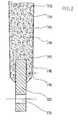
- the abrasive active ring element 1 consists of a abrasive mass, for example, resin-bonded multi-component mixtures are used in which as an organic binder 15 ( Fig.2 ) preferably pure or modified phenolic resins are used.
- organic binder 15 preferably pure or modified phenolic resins
- other resins such as epoxy resins, urea resins (melamine resins), coumarone resins, isocyanates, polyamides of polyimides, etc. can be used as a binder 15 are used.
- abrasive masses receive a wide variety of abrasive grain types, which differ in size, composition and physical properties.
- CBN cubic boron nitride
- PCD polycrystalline diamonds
- abrasive masses additionally contain reinforcing elements.
- Kevlar or carbon fiber fabric 18 FOG. Fig.2
- Metal and mineral fibers 16 Fig.2
- whiskers so-called whiskers
- abrasive masses 12 contain fillers 17 (FIG. Fig.2 ), with the help of which it is possible to vary the structure and the structure of the grinding mass or to achieve a modified cutting or cooling behavior. Even the control of the energy absorption in the separation process can be influenced by fillers.
- a taper 19 (FIG. Fig.2 ) of the abrasive ring element 1 from the ring element outer edge toward the center.
- the taper angle 19 should be between 0.1 and 3 degrees, preferably between 0.15 and 0.5 degrees. While the abrasive active range of standard cutting discs can be processed to 50% of the outer diameter, the sanding active ring element 1 according to the invention, the processing of the abrasive mass succeeds to 95%.
- the abrasive-active ring element 1 is connected to a carrier element 23 which can be brought into releasable engagement with the ring-fixing device 2 ( Fig.2 ).
- the carrier element 23 (FIG. Figure 3 ) is just like the abrasive ring element 1 ring-shaped and embedded on the inner peripheral side of the abrasive ring active element 1 partially in this positive and non-positive by the abrasive mass 12 of the ring member 1 is pressed onto the support member 23.
- a multi-part embodiment of the carrier element 23 is shown in FIG Figure 3 shown.
- the type of design depends on the choice of the carrier element material and on the size (dimension) of the carrier element.
- Become a one-piece support elements Preferably used when the carrier elements are small (diameter 300 to 1000 mm) and used as a carrier material non-ferrous metals, composites or high-strength and thermally stable plastics.
- Multi-part support elements are generally used in large-sized cut-off wheels and are preferably made of steel.
- a carrier element 23 consists of a plurality, at least two, preferably four or six, segments 26, the shape of the connecting regions of the segment abutments 20, 21 in each case requires a special type of connection.
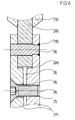
- straight segment connections 20 (FIG. Figure 6 )
- the connection of the segments is preferably carried out by welding.
- anchor elements or meanders these can either be glued or welded.
- the carrier element 23 imparts exceptional strength and stability to the composite grinding system according to the invention and provides an extremely high resistance to the deflections occurring during the separating process.
- the carrier element 23 further features that cause a fixation of the abrasive mass 12 on the carrier element 23 in addition to the usual reinforcing elements such as fabric 18, whiskers 16 and so on.
- edge-open contour elements 22 FIG. Fig.2
- the shape of the contour elements 22 can vary from simple geometric to polygonal or even irregularly curved shapes depending on the purpose and applied materials.
- the support member 23 also includes cam holes 13. Their number depends on the disc diameter and is between two and twenty, preferably between eight and sixteen.
- the thickness of the carrier ring depends on the total thickness of the cut-off wheel. It can be between 20 and 70% of the total thickness of the cutting wheel, but preferably between 30 and 50%.
- the Ringfixiervorides 2 is composed of two adjacent disk-shaped Fixierplatten comprisen 11, which are stretched in its central region by the flange 4 to the rotatable drive member 37.
- a centering device 3 is provided for centering the abrasive-active ring element 1 relative to the ring-fixing device 2, wherein the carrier element 23 in the use state (US Pat. Fig.1 ) is clamped at its projecting from the ring member 1 side surfaces by the centering device 3 partially in the Ringfixiervorraum 2.
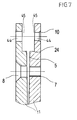
- the carrier element 23 with the already mentioned, along its peripheral region arranged driver bores 13 (FIG. Fig.2 . Figure 3 ) and the Ringfixiervorides 2 with corresponding holes 44 ( Figure 7 ), are passed through the driving pin 9 for fixing the abrasive ring active element 1 at the Ringfixiervorraum 2.
- the driving pins 9 are fastened to bolt fixing areas 10 with one end in the ring fixing device 2.
- the two fixing plate 11 have at opposite ends Areas circumferential recesses 45 ( Figure 7 ), between which the annular support member 23 is partially received, the corresponding to the Mitauerbohrened 13 holes 44 extend transversely through the circumferential grooves 45 of the Fixierplattenimplantation 11 therethrough.
- the circumferential depressions 45 are on their side near the center by a radial centering surface 24 (FIG. Figure 6 . Figure 7 ) is limited, on which the carrier element 23 is mounted.
- the centering device 3 includes attractable clamping elements 6, via which the Fixierplatten implant 11 are clamped in the peripheral region against the side surfaces of the support member 23, wherein the centering 5 decreases when tightening the clamping elements 6 by elastic deformation of the Fixierplattenimplantation 11 and whereby the abrasive ring active element 1 with respect to the fixing plate 11 is positioned centered.
- the attractable clamping elements 6 are formed by countersunk screws which can be guided through a counterbore 8 in one of the fixing plate elements 11 and screwed into a threaded hole 7 of the other of the fixing plate elements 11, so that the fixing plate elements 11 are clamped against the side surfaces of the carrier element 23 by tightening the countersunk screws ,
- the centering device 3 is integrated into the two Fixierplattenimplantation 11 and ensures by clamping the support member 23 between the Fixierplattenimplantation 11 sure that the abrasive ring active element 1 is centered to the fixing elements 11 and thus allows a side impact-free running of the cutting disc.
- the annular support member 23 is mounted on the radial centering surface 24 of the Fixierplattenimplantation 11.
- the actual fixation of the carrier element 23 thus takes place by means of the countersunk screws 6 which clamp the two fixing plate elements 11 together.
- the number of countersunk screws 6 depends on the size of the cutting disc, but should not fall below four.
- FIG. 7 shows the Fixierplattenimplantation 11 without the support member 23 and without screwed countersunk screw.
- the drive energy of the drive element, not shown on the abrasive ring active element 1 of the blade is by the fixing plate elements 11 are transmitted, which includes the centering device 3, the corresponding holes 44 for the driving pins 9, the radial centering surface 24, the countersunk hole 8 and the threaded hole 7 for the countersunk screws 6.
- the Fixierplattenetti 11 may be made of non-ferrous metals, composites or high-strength and heat-resistant organic materials, because of the large mechanical and physical stress, these are preferably made of steel.
- the fixing plate members 11 may be formed independently of the machine flanges, or one of the fixing plate members 11 may be fixedly connected to the machine flange member 4.
- the particular advantage of the Fixierplattenimplantation 11 is that the abrasive active ring element 1 can be easily changed by this invention parameters, without having to come to a change of Fixierplattenimplantation.
- the centering device 3 guarantees optimal stability and safety during the separation process.
Landscapes
- Engineering & Computer Science (AREA)
- Mechanical Engineering (AREA)
- Polishing Bodies And Polishing Tools (AREA)
- Finish Polishing, Edge Sharpening, And Grinding By Specific Grinding Devices (AREA)
Applications Claiming Priority (1)
| Application Number | Priority Date | Filing Date | Title |
|---|---|---|---|
| ATA68/2010A AT509371B1 (de) | 2010-01-20 | 2010-01-20 | Verbundschleifsystem |
Publications (2)
| Publication Number | Publication Date |
|---|---|
| EP2353783A2 true EP2353783A2 (fr) | 2011-08-10 |
| EP2353783A3 EP2353783A3 (fr) | 2015-09-23 |
Family
ID=43971142
Family Applications (1)
| Application Number | Title | Priority Date | Filing Date |
|---|---|---|---|
| EP11450005.1A Withdrawn EP2353783A3 (fr) | 2010-01-20 | 2011-01-19 | Système de rectification composite |
Country Status (2)
| Country | Link |
|---|---|
| EP (1) | EP2353783A3 (fr) |
| AT (1) | AT509371B1 (fr) |
Citations (4)
| Publication number | Priority date | Publication date | Assignee | Title |
|---|---|---|---|---|
| AT338130B (de) | 1973-08-13 | 1977-08-10 | Braun S Sohne J | Trennschleifscheibe |
| EP0769352A1 (fr) | 1995-10-18 | 1997-04-23 | Rappold International Sales AG | Disque abrasif feuilleté |
| EP1332834A1 (fr) | 2002-01-24 | 2003-08-06 | Tyrolit Schleifmittelwerke Swarovski KG | Meule de tronçonnage avec tôles latérales d'acier |
| AT502285A1 (de) | 2004-10-19 | 2007-02-15 | Gissing Gerhard | Trennschleifring |
Family Cites Families (4)
| Publication number | Priority date | Publication date | Assignee | Title |
|---|---|---|---|---|
| DE423067C (de) * | 1925-12-22 | Robert Hesse | Schleif- und Polierscheibe | |
| FR753829A (fr) * | 1932-06-10 | 1933-10-25 | Emil Offenbacher A G | Disques d'affûtage coupeurs |
| US3793783A (en) * | 1972-10-02 | 1974-02-26 | Norton Co | Segmental cut-off grinding wheel |
| AT318424B (de) * | 1973-04-02 | 1974-10-25 | Swarovski Tyrolit Schleif | Segmentschleifscheibe |
-
2010
- 2010-01-20 AT ATA68/2010A patent/AT509371B1/de not_active IP Right Cessation
-
2011
- 2011-01-19 EP EP11450005.1A patent/EP2353783A3/fr not_active Withdrawn
Patent Citations (4)
| Publication number | Priority date | Publication date | Assignee | Title |
|---|---|---|---|---|
| AT338130B (de) | 1973-08-13 | 1977-08-10 | Braun S Sohne J | Trennschleifscheibe |
| EP0769352A1 (fr) | 1995-10-18 | 1997-04-23 | Rappold International Sales AG | Disque abrasif feuilleté |
| EP1332834A1 (fr) | 2002-01-24 | 2003-08-06 | Tyrolit Schleifmittelwerke Swarovski KG | Meule de tronçonnage avec tôles latérales d'acier |
| AT502285A1 (de) | 2004-10-19 | 2007-02-15 | Gissing Gerhard | Trennschleifring |
Also Published As
| Publication number | Publication date |
|---|---|
| EP2353783A3 (fr) | 2015-09-23 |
| AT509371A1 (de) | 2011-08-15 |
| AT509371B1 (de) | 2013-01-15 |
Similar Documents
| Publication | Publication Date | Title |
|---|---|---|
| EP1812206B1 (fr) | Anneau de tronçonneuse à double dispositif de serrage médian | |
| EP3015222B1 (fr) | Disque de meulage | |
| EP3038795B1 (fr) | Outil abrasif à fibres vulcanisées | |
| EP0351543B1 (fr) | Meule de rectification | |
| WO2016124221A1 (fr) | Outil de fraisage pour meuleuse d'angle | |
| EP2810739B1 (fr) | Outil destiné au traitement de matériaux | |
| AT509372B1 (de) | Verbundschleifsystem | |
| DE3687770T2 (de) | Verfahren zum einbauen von steinen in platten- oder mahlvorrichtungen. | |
| AT509371B1 (de) | Verbundschleifsystem | |
| DE20313038U1 (de) | Messer für Schneidmaschinen | |
| EP0981421B1 (fr) | Meule de rectification pour lame scie circulaire metaux | |
| WO2009121461A1 (fr) | Outil de brochage rotatif par tournage ou de fraisage de profil | |
| EP2712337B1 (fr) | Meule de tronçonnage | |
| EP0614726B1 (fr) | Dispositif pour rectifier, en particulier pour enlever du béton et des pièrres naturelles | |
| EP3053719B1 (fr) | Outil de fraisage pour meuleuse d'angle et utilisation de cet outil | |
| DE102013017962A1 (de) | Verbessertes Vulkanfiber-Schleifwerkzeug | |
| EP1888285B1 (fr) | Outil de rectification | |
| DE934209C (de) | Riemenscheibe zum Antrieb von Flachriemen oder Schleifbaendern | |
| DE202006002850U1 (de) | Kreissägeblatt | |
| DE20303341U1 (de) | Schleifkörper | |
| DE202007012295U1 (de) | Sägeblatt | |
| DE202013010146U1 (de) | Verbessertes Vulkanfiber-Schleifwerkzeug | |
| DE202015008807U1 (de) | Rundlaufender Schleifkörper | |
| DE19738394A1 (de) | Schleifwerkzeug | |
| DE9403302U1 (de) | Schleifwerkzeug zur Herstellung einer Nut in einem Mauerwerk |
Legal Events
| Date | Code | Title | Description |
|---|---|---|---|
| PUAI | Public reference made under article 153(3) epc to a published international application that has entered the european phase |
Free format text: ORIGINAL CODE: 0009012 |
|
| AK | Designated contracting states |
Kind code of ref document: A2 Designated state(s): AL AT BE BG CH CY CZ DE DK EE ES FI FR GB GR HR HU IE IS IT LI LT LU LV MC MK MT NL NO PL PT RO RS SE SI SK SM TR |
|
| AX | Request for extension of the european patent |
Extension state: BA ME |
|
| PUAL | Search report despatched |
Free format text: ORIGINAL CODE: 0009013 |
|
| AK | Designated contracting states |
Kind code of ref document: A3 Designated state(s): AL AT BE BG CH CY CZ DE DK EE ES FI FR GB GR HR HU IE IS IT LI LT LU LV MC MK MT NL NO PL PT RO RS SE SI SK SM TR |
|
| AX | Request for extension of the european patent |
Extension state: BA ME |
|
| RIC1 | Information provided on ipc code assigned before grant |
Ipc: B24D 5/16 20060101ALI20150817BHEP Ipc: B24D 5/12 20060101AFI20150817BHEP |
|
| STAA | Information on the status of an ep patent application or granted ep patent |
Free format text: STATUS: THE APPLICATION HAS BEEN WITHDRAWN |
|
| 18W | Application withdrawn |
Effective date: 20160222 |