EP2353882A1 - Support de plaque d'impression lithographique, son procédé de fabrication et plaque présensibilisée - Google Patents
Support de plaque d'impression lithographique, son procédé de fabrication et plaque présensibilisée Download PDFInfo
- Publication number
- EP2353882A1 EP2353882A1 EP11152492A EP11152492A EP2353882A1 EP 2353882 A1 EP2353882 A1 EP 2353882A1 EP 11152492 A EP11152492 A EP 11152492A EP 11152492 A EP11152492 A EP 11152492A EP 2353882 A1 EP2353882 A1 EP 2353882A1
- Authority
- EP
- European Patent Office
- Prior art keywords
- lithographic printing
- treatment
- aluminum
- printing plate
- treatment step
- Prior art date
- Legal status (The legal status is an assumption and is not a legal conclusion. Google has not performed a legal analysis and makes no representation as to the accuracy of the status listed.)
- Granted
Links
Images


Classifications
-
- B—PERFORMING OPERATIONS; TRANSPORTING
- B41—PRINTING; LINING MACHINES; TYPEWRITERS; STAMPS
- B41N—PRINTING PLATES OR FOILS; MATERIALS FOR SURFACES USED IN PRINTING MACHINES FOR PRINTING, INKING, DAMPING, OR THE LIKE; PREPARING SUCH SURFACES FOR USE AND CONSERVING THEM
- B41N3/00—Preparing for use and conserving printing surfaces
- B41N3/03—Chemical or electrical pretreatment
- B41N3/034—Chemical or electrical pretreatment characterised by the electrochemical treatment of the aluminum support, e.g. anodisation, electro-graining; Sealing of the anodised layer; Treatment of the anodic layer with inorganic compounds; Colouring of the anodic layer
-
- C—CHEMISTRY; METALLURGY
- C25—ELECTROLYTIC OR ELECTROPHORETIC PROCESSES; APPARATUS THEREFOR
- C25D—PROCESSES FOR THE ELECTROLYTIC OR ELECTROPHORETIC PRODUCTION OF COATINGS; ELECTROFORMING; APPARATUS THEREFOR
- C25D11/00—Electrolytic coating by surface reaction, i.e. forming conversion layers
- C25D11/02—Anodisation
- C25D11/04—Anodisation of aluminium or alloys based thereon
- C25D11/12—Anodising more than once, e.g. in different baths
-
- B—PERFORMING OPERATIONS; TRANSPORTING
- B41—PRINTING; LINING MACHINES; TYPEWRITERS; STAMPS
- B41N—PRINTING PLATES OR FOILS; MATERIALS FOR SURFACES USED IN PRINTING MACHINES FOR PRINTING, INKING, DAMPING, OR THE LIKE; PREPARING SUCH SURFACES FOR USE AND CONSERVING THEM
- B41N1/00—Printing plates or foils; Materials therefor
- B41N1/04—Printing plates or foils; Materials therefor metallic
- B41N1/08—Printing plates or foils; Materials therefor metallic for lithographic printing
- B41N1/083—Printing plates or foils; Materials therefor metallic for lithographic printing made of aluminium or aluminium alloys or having such surface layers
Definitions
- the present invention relates to a lithographic printing plate support, a method of manufacturing such a lithographic printing plate support and a presensitized plate.
- Lithographic printing is a printing process that makes use of the inherent immiscibility of water and oil.
- Lithographic printing plates used in lithographic printing have formed on a surface thereof regions which are receptive to water and repel oil-based inks (referred to below as “non-image areas”) and regions which repel water and are receptive to oil-based inks (referred to below as “image areas”).
- the aluminum support employed in a lithographic printing plate (referred to below simply as a "lithographic printing plate support”) is used in such a way as to carry non-image areas on its surface. It must therefore have a number of conflicting properties, including, on the one hand, an excellent hydrophilicity and water retention and, on the other hand, an excellent adhesion to the image recording layer that is provided thereon. If the hydrophilicity of the support is too low, ink is likely to be attached to the non-image areas at the time of printing, causing a blanket cylinder to be scummed and thereby causing so-called scumming to be generated. In addition, if the water receptivity of the support is too low, clogging in the shadow area is generated unless the amount of fountain solution is increased at the time of printing. Thus, a so-called water allowance is narrowed.
- JP 11-291657 A1 discloses a method of manufacturing a lithographic printing plate support which includes a first step for anodizing a roughened aluminum plate surface and a second step for reanodizing under such conditions that the diameter of micropores may be smaller than in the anodized film formed in the first step. It is described that the lithographic printing plate obtained by using the lithographic printing plate support does not deteriorate the ink eliminability, improves the adhesion to the photosensitive layer, does not cause highlight areas to be blocked up, and has a long press life.
- printing may be temporarily stopped.
- the lithographic printing plate is left to stand on the plate cylinder and its non-image areas may be scummed under the influence of the contamination in the atmosphere. Therefore, when the printing having been temporarily stopped is resumed, a number of sheets are to be printed before normal printing is performed, thus printing useless sheets or causing other defect. It is known that these defects prominently occur in the lithographic printing plates having undergone electrochemical graining treatment in an acidic solution containing hydrochloric acid.
- the number of sheets wasted when the printing having been temporarily stopped is resumed is used to evaluate the deinking ability when left to stand and the deinking ability is rated "good" when the number of wasted sheets is small.
- One of the methods for eliminating a treatment step is a method called "on-press development" in which an exposed presensitized plate is mounted on a plate cylinder of a printing press and fountain solution and ink are supplied as the plate cylinder is rotated to thereby remove non-image areas of the presensitized plate.
- this is a system in which the exposed presensitized plate is mounted on the printing press without any further treatment so that development completes in the usual printing process.
- the presensitized plate suitable for use in such on-press development is required to have an image recording layer which is soluble in fountain solution or an ink solvent and to have a light-room handling property capable of development on a printing press placed in a light room.
- the inventors of the invention have made an intensive study on various properties of the lithographic printing plate and the presensitized plate obtained by using a lithographic printing plate support specifically described in JP 11-291657 A1 and found that the press life has a trade-off relation with the deinking ability of the lithographic printing plate when it is left to stand or the on-press developability and these properties cannot be simultaneously achieved, which is not necessarily satisfactory in practical use. In addition, it has been found that the scratch resistance of the lithographic printing plate support is also to be improved.
- an object of the invention is to provide a lithographic printing plate support that has excellent scratch resistance and is capable of obtaining a presensitized plate which exhibits excellent on-press developability and enables a lithographic printing plate formed therefrom to have a long press life and excellent deinking ability when left to stand.
- Another object of the invention is to provide a method of manufacturing such a lithographic printing plate support.
- Still another object of the invention is to provide a presensitized plate.
- the inventors of the invention have made an intensive study to achieve the objects and as a result found that the foregoing problems can be solved by controlling the micropore shape in the anodized film.
- the invention provides the following (1) to (11).
- the invention can provide a lithographic printing plate support which has excellent scratch resistance and is capable of obtaining a lithographic printing plate having a long press life and excellent deinking ability when left to stand, a manufacturing method thereof and a presensitized plate using such a lithographic printing plate support.
- the press life can be particularly improved while maintaining the on-press developability.
- the lithographic printing plate support of the invention includes an aluminum plate and an anodized film formed thereon, each of micropores in the anodized film being of such a shape that a large-diameter portion having a larger average diameter communicates with a small-diameter portion having a smaller average diameter along the depth direction (i.e., the thickness direction of the film).
- the press life has been deemed to have a trade-off relation with the deinking ability of the lithographic printing plate when it is left to stand or the on-press developability, these properties can be simultaneously achieved at a higher level by controlling the average diameter and depth of the large-diameter portions having a larger average diameter in the micropores.
- the surface occupation ratio of micropores represented by the following general formula can be improved to obtain a lithographic printing plate having a longer press life.
- Occupation ratio of micropores density of micropores x (average diameter of large-diameter portions / 2) 2 x n
- FIG. 1 is a schematic cross-sectional view showing an embodiment of the lithographic printing plate support of the invention.
- a lithographic printing plate support 10 shown in FIG. 1 is of a laminated structure in which an aluminum plate 12 and an anodized aluminum film 14 are stacked in this order.
- the anodized film 14 has micropores 16 extending from its surface toward the aluminum plate 12 side, and each micropore 16 has a large-diameter portion 18 and a small-diameter portion 20.
- the aluminum plate 12 and the anodized film 14 are first described in detail.
- the aluminum plate 12 (aluminum support) used in the invention is made of a dimensionally stable metal composed primarily of aluminum; that is, aluminum or aluminum alloy.
- the aluminum plate is selected from among plates of pure aluminum, alloy plates composed primarily of aluminum and containing small amounts of other elements, and plastic films or paper on which aluminum (alloy) is laminated or vapor-deposited.
- a composite sheet as described in JP 48-18327 A in which an aluminum sheet is attached to a polyethylene terephthalate film may be used.
- the above-described plates made of aluminum or aluminum alloys are referred to collectively as "aluminum plate 12."
- Other elements which may be present in the aluminum alloy include silicon, iron, manganese, copper, magnesium, chromium, zinc, bismuth, nickel and titanium. The content of other elements in the alloy is not more than 10 wt%.
- the aluminum plate used is preferably made of pure aluminum but may contain small amounts of other elements because it is difficult to manufacture completely pure aluminum from the viewpoint of smelting technology.
- the aluminum plate 12 which is applied to the invention as described above is not specified for its composition but conventionally known materials such as JIS A1050, JIS A1100, JIS A3103 and JIS A3005 can be appropriately used.
- the aluminum plate 12 used in the invention is treated as it continuously travels usually in a web form, and has a width of about 400 mm to about 2,000 mm and a thickness of about 0.1 mm to about 0.6 mm. This thickness may be changed as appropriate based on such considerations as the size of the printing press, the size of the printing plate and the desires of the user.
- the aluminum plate is appropriately subjected to substrate surface treatments to be described later.
- the anodized film 14 refers to an anodized aluminum film that is generally formed at a surface of the aluminum plate 12 by anodizing treatment and has the micropores 16 which are subsutantially vertical to the film surface and are individually distributed in a uniform manner.
- the micropores 16 extend along the thickness direction of the anodized film 14 from the surface of the anodized film opposite to the aluminum plate 12 toward the aluminum plate 12 side.
- Each micropore 16 in the anodized film 14 has the large-diameter portion 18 which extends to a depth of 5 to 60 nm from the anodized film surface (depth A: see FIG. 1 ), and the small-diameter portion 20 which communicates with the bottom of the large-diameter portion 18 and further extends to a depth of 900 to 2,000 nm from the communication position.
- the large-diameter portion 18 and the small-diameter portion 20 are described below in detail.
- the large-diameter portions 18 have an average diameter (average aperture size) of more than 60 nm but up to 100 nm at the surface of the anodized film.
- the average diameter is preferably more than 60 nm but up to 85 nm from the viewpoint that the lithographic printing plate obtained by using the lithographic printing plate support has a longer press life.
- the lithographic printing plate obtained by using the lithographic printing plate support can have a long press life and excellent deinking ability when left to stand and the presensitized plate obtained by using the support can have excellent on-press developability.
- an average diameter in excess of 100 nm an increase in the surface area and an improvement of the press life cannot be expected.
- the average diameter of the large-diameter portions 18 is determined as follows: The surface of the anodized film 14 is taken by FE-SEM at a magnification of 150,000X to obtain four images, and in the resulting four images, the diameter of the micropores (large-diameter portions) within an area of 400 x 600 nm 2 is measured and the average of the measurements is calculated.
- the equivalent circle diameter is used if the aperture of the large-diameter portion 18 is not circular.
- the "equivalent circle diameter” refers to a diameter of a circle assuming that the shape of an aperture is the circle having the same projected area as that of the aperture.
- each large-diameter portion 18 is at a depth of 5 to 60 nm from the surface of the anodized film (hereinafter this depth is also referred to as "depth A").
- each large-diameter portion 18 is a pore which extends from the surface of the anodized film in the depth direction (thickness direction) to a depth of 5 to 60 nm.
- the depth is preferably from 7 nm to 50 nm from the viewpoint that the lithographic printing plate obtained by using the lithographic printing plate support has a longer press life and more excellent deinking ability when left to stand and the presensitized plate obtained by using the support can have excellent on-press developability.
- the lithographic printing plate has a shorter press life.
- the lithographic printing plate has poor deinking ability when left to stand and the presensitized plate has poor on-press developability.
- the depth is determined by taking a cross-sectional image of the anodized film 14 at a magnification of 150,000X, measuring the depth of at least 25 large-diameter portions, and calculating the average of the measurements.
- the ratio of the depth A of the large-sized portions 18 to their bottom to the average diameter of the large-sized portions 18 is from 0.05 to 0.95. Within the foregoing range, a desired effect is obtained.
- the ratio of the depth A to the average diameter is preferably at least 0.1 but less than 0.8 from the viewpoint that the lithographic printing plate obtained by using the lithographic printing plate support has a longer printing press and more excellent deinking ability when left to stand and the presensitized plate obtained by using the support can have excellent on-press developability.
- the lithographic printing plate At a ratio of the depth A to the average diameter of less than 0.05, the lithographic printing plate has a shorter press life. At a ratio of the depth A to the average diameter in excess of 0.95, the lithographic printing plate has poor deinking ability when left to stand and the presensitized plate has poor on-press developability.
- the shape of the large-diameter portions 18 is not particularly limited. Exemplary shapes include a substantially hemispherical shape, a substantially straight tubular shape (substantially columnar shape), and a conical shape in which the diameter is decreased in the depth direction, and a substantially hemispherical shape is preferred.
- the bottom shape of the large-diameter portions 18 is not particularly limited and may be curved (convex) or flat.
- the internal diameter of the large-diameter portions 18 is not particularly limited but is typically substantially equal to or smaller than the diameter of the apertures. There may be a difference of about 1 nm to about 30 nm between the internal diameter of the large-diameter portions 18 and the diameter of the apertures.
- each of the small-diameter portions 20 is a pore which communicates with the bottom of the corresponding large-diameter portion 18 and further extends from the communication position in the depth direction.
- One small-diameter portion 20 usually communicates with one large-diameter portion 18 but two or more small-diameter portions 20 may communicate with one large-diameter portion 18.
- the small-diameter portions 20 have an average diameter at the communication position of more than 0 but less than 15 nm.
- the average diameter is preferably not more than 10 nm and more preferably from 5 to 10 nm in terms of deinking ability of the lithographic printing plate when it is left to stand and on-press developability of the presensitized plate.
- the lithographic printing plate obtained by using the lithographic printing plate support of the invention has poor deinking ability when left to stand and poor on-press developability.
- the average diameter of the small-diameter portions 20 is determined as follows: The surface of the anodized film 14 is taken by FE-SEM at a magnification of 150,000X to obtain four images, and in the resulting four images, the diameter of the micropores (small-diameter portions) within an area of 400 x 600 nm 2 is measured and the average of the measurements is calculated.
- the equivalent circle diameter is used if the aperture of the small-diameter portion 20 is not circular.
- the "equivalent circle diameter” refers to a diameter of a circle assuming that the shape of an aperture is the circle having the same projected area as that of the aperture.
- each small-diameter portion 20 is at a distance of 900 to 2,000 nm in the depth direction from the communication position with the corresponding large-diameter portion 18 which has the depth A up to the communication position.
- the small-diameter portions 20 are pores each of which further extends in the depth direction (thickness direction) from the communication position with the corresponding large-diameter portion 18 and the small-diameter portions 20 have a length of 900 to 2,000 nm.
- the bottom of each small-sized portion 20 is preferably at a depth of 900 to 1,500 nm from the communication position in terms of the scratch resistance of the lithographic printing plate support.
- the lithographic printing plate support has poor scratch resistance.
- the lithographic printing plate support requires a prolonged treatment time and suffers from low productivity and economic efficiency.
- the depth is determined by taking a cross-sectional image of the anodized film 14 at a magnification of 150,000X, measuring the depth of at least 25 small-diameter portions, and calculating the average of the measurements.
- the ratio between the average diameter of the large-diameter portions 18 at the surface of the anodized film and that of the small-diameter portions 20 at the communication position is preferably more than 5.0, more preferably more than 6.0, and most preferably from 7.5 to 12.5.
- the resulting lithographic printing plate has a longer press life and more excellent deinking ability when left to stand and the presensitized plate has more excellent on-press developability.
- the shape of the small-diameter portions 20 is not particularly limited. Exemplary shapes include a substantially straight tubular shape (substantially columnar shape), and a conical shape in which the diameter is decreased in the depth direction, and a substantially straight tubular shape is preferred.
- the bottom shape of the small-diameter portions 20 is not particularly limited and may be curved (convex) or flat.
- the internal diameter of the small-diameter portions 20 is not particularly limited but is typically substantially equal to or smaller than the diameter at the communication positions. There may be a difference of about 10 nm to about 90 nm between the internal diameter of the small-diameter portions 20 and the diameter of the apertures.
- the density of the micropores 16 in the anodized film 14 is not particularly limited and the anodized film 14 preferably has 50 to 4,000 micropores/ ⁇ m 2 , and more preferably 100 to 3,000 micropores/ ⁇ m 2 in terms of longer press life, and more excellent deinking ability when left to stand of the resulting lithographic printing plate and more excellent on-press developability of the presensitized plate.
- the coating weight of the anodized film 14 is not particularly limited and is preferably from 2.3 to 5.5 g/m 2 and more preferably from 2.3 to 4.0 g/m 2 in terms of more excellent scratch resistance of the resulting lithographic printing plate.
- the occupation ratio of the micropores 16 represented by the following formula is not particularly limited and is preferably at least 2.0 and more preferably from 2.5 to 3.5 in terms of longer press life, and more excellent deinking ability when left to stand of the resulting lithographic printing plate and more excellent on-press developability of the presensitized plate.
- Occupation ratio of micropores density of micropores x (average diameter of large-diameter portions / 2) 2 x n
- the volume fraction of the micropores 16 represented by the following formula is a parameter on the volume of the large-diameter portions and is preferably from 50 to 150 and more preferably from 55 to 140 in terms of longer press life, and more excellent deinking ability when left to stand of the resulting lithographic printing plate and more excellent on-press developability of the presensitized plate.
- volume fraction of micropores occupation ratio of micropores x depth of large-diameter portions
- the above-described lithographic printing support having an image recording layer to be described later formed on a surface thereof can be used as a presensitized plate.
- the method of manufacturing the lithographic printing plate support of the invention is not particularly limited and a manufacturing method in which the following steps are performed in order is preferred.
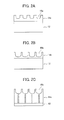
- FIGS. 2A-2C and 3A-3C are schematic cross-sectional views showing a substrate and an anodized film between the first anodizing treatment step and the second anodizing treatment step in the order of steps.
- the surface roughening treatment step is a step in which the surface of the aluminum plate is subjected to surface roughening treatment including electrochemical graining treatment. This step is preferably performed before the first anodizing treatment step to be described later but may not be performed if the aluminum plate already has a preferred surface shape.
- Electrochemical graining treatment may only be performed for the surface roughening treatment, but electrochemical graining treatment may be performed in combination with mechanical graining treatment and/or chemical graining treatment.
- mechanical graining treatment is preferably followed by electrochemical graining treatment.
- electrochemical graining treatment is preferably performed in an aqueous solution of nitric acid or hydrochloric acid.
- Mechanical graining treatment is generally performed in order that the surface of the aluminum plate may have a surface roughness R a of 0.35 to 1.0 ⁇ m.
- mechanical graining treatment is not particularly limited for its conditions and can be performed according to the method described in, for example, JP 50-40047 B .
- Mechanical graining treatment can be performed by brush graining using a suspension of pumice or a transfer system.
- Chemical graining treatment is also not particularly limited and may be performed by any known method.
- Mechanical graining treatment is preferably followed by chemical etching treatment described below.
- chemical etching treatment following mechanical graining treatment is to smooth edges of irregularities at the surface of the aluminum plate to prevent ink from catching on the edges during printing, to improve the deinking ability of the lithographic printing plate, and to remove abrasive particles or other unnecessary substances remaining on the surface.
- etching processes including etching using an acid and etching using an alkali are known in the art, and an exemplary method which is particularly excellent in terms of etching efficiency includes chemical etching treatment using an aqueous alkali solution. This treatment is hereinafter referred to as "alkali etching treatment.”
- Alkaline agents that may be used in the alkali solution are not particularly limited and illustrative examples of suitable alkaline agents include sodium hydroxide, potassium hydroxide, sodium metasilicate, sodium carbonate, sodium aluminate, and sodium gluconate .
- the alkaline agents may contain aluminum ions.
- the alkali solution has a concentration of preferably at least 0.01 wt% and more preferably at least 3 wt%, but preferably not more than 30 wt% and more preferably not more than 25 wt%.
- the alkali solution has a temperature of preferably room temperature or higher, and more preferably at least 30°C, but preferably not more than 80°C, and more preferably not more than 75°C.
- the amount of material removed from the aluminum plate (also referred to below as the "etching amount”) is preferably at least 0.1 g/m 2 and more preferably at least 1 g/m 2 , but preferably not more than 20 g/m 2 and more preferably not more than 10 g/m 2 .
- the treatment time is preferably from 2 seconds to 5 minutes depending on the etching amount and more preferably from 2 to 10 seconds in terms of improving the productivity.
- chemical etching treatment using an acid solution at a low temperature (hereinafter also referred to as "desmutting treatment”) is preferably performed to remove substances produced by alkali etching treatment.
- Acids that may be used in the acid solution are not particularly limited and illustrative examples thereof include sulfuric acid, nitric acid and hydrochloric acid.
- the acid solution preferably has a concentration of 1 to 50 wt%.
- the acid solution preferably has a temperature of 20 to 80°C. When the concentration and temperature of the acid solution fall within the above-defined ranges, a lithographic printing plate obtained by using the inventive lithographic printing plate support has a more improved resistance to spotting.
- the surface roughening treatment is a treatment in which electrochemical graining treatment is performed after mechanical graining treatment and chemical etching treatment are performed as desired, but also in cases where electrochemical graining treatment is performed without performing mechanical graining treatment, electrochemical graining treatment may be preceded by chemical etching treatment using an aqueous alkali solution such as sodium hydroxide. In this way, impurities which are present in the vicinity of the surface of the aluminum plate can be removed.
- Electrochemical graining treatment easily forms fine pits at the surface of the aluminum plate and is therefore suitable to prepare a lithographic printing plate having excellent printability.
- Electrochemical graining treatment is performed in an aqueous solution containing nitric acid or hydrochloric acid as its main ingredient using direct or alternating current.
- Electrochemical graining treatment is preferably followed by chemical etching treatment described below. Smut and intermetallic compounds are present at the surface of the aluminum plate having undergone electrochemical graining treatment.
- chemical etching treatment following electrochemical graining treatment it is preferable for chemical etching using an alkali solution (alkali etching treatment) to be first performed particularly in order to remove smut with high efficiency.
- the conditions in chemical etching using an alkali solution preferably include a treatment temperature of 20 to 80°C and a treatment time of 1 to 60 seconds. It is desirable for the alkali solution to contain aluminum ions.
- desmutting treatment is preferably performed to remove smut efficiently.
- chemical etching treatment is not particularly limited and may be performed by immersion, showering, coating or other process.
- the first anodizing treatment step is a step in which an anodized aluminum film having micropores which extend in the depth direction (thickness direction) of the film is formed at the surface of the aluminum surface by performing anodizing treatment on the aluminum plate having undergone the above-described surface roughening treatment. As shown in FIG. 2A , as a result of the first anodizing treatment step, an anodized aluminum film 14a bearing micropores 16a is formed at a surface of an aluminum substrate 12.
- the first anodizing treatment may be performed by any method known in the art but the manufacturing conditions are appropriately set so that the foregoing micropores 16 may be eventually formed.
- the average diameter (average aperture size) of the micropores 16a formed in the first anodizing treatment step is typically from about 4 nm to about 40 nm and preferably 7 nm to 30 nm. An average diameter within this range facilitates the formation of the micropores 16 having the specified shapes and the resulting lithographic printing plate and presensitized plate have more excellent properties.
- the micropores 16a typically have a depth of at least about 5 nm but less than about 80 nm and preferably 15 nm to 60 nm. A depth within this range facilitates the formation of the micropores 16 having the specified shapes and the resulting lithographic printing plate and presensitized plate have more excellent properties.
- the density of the micropores 16a is not particularly limited and is preferably 50 to 4,000 micropores/ ⁇ m 2 , and more preferably 100 to 3,000 micropores/ ⁇ m 2 .
- the lithographic printing plate formed by using the lithographic printing plate support obtained after the above-described steps has a long press life and excellent deinking ability when left to stand and then presensitized plate has excellent on-press developability.
- the anodized film obtained by the first anodizing treatment step typically has a thickness of 10 to 90 nm and preferably 15 to 80 nm.
- the lithographic printing plate formed by using the lithographic printing plate support obtained after the above-described steps has a long press life and excellent deinking ability when left to stand and the presensitized plate has excellent on-press developability.
- the anodized film obtained by the first anodizing treatment step typically has a coating weight of 0.03 to 0.3 g/m 2 and preferably 0.12 to 0.25 g/m 2 .
- the lithographic printing plate formed by using the lithographic printing plate support obtained after the above-described steps has a long press life and excellent deinking ability when left to stand and the presensitized plate has excellent on-press developability.
- aqueous solutions of acids such as sulfuric acid, phosphoric acid and oxalic acid may be mainly used for the electrolytic solution.
- aqueous solutions or non-aqueous solutions containing chromic acid, sulfamic acid, benzenesulfonic acid or a combination of two or more thereof may also be used.
- the anodized film can be formed at the surface of the aluminum plate by passing direct current or alternating current through the aluminum plate in the electrolytic solution as described above.
- the electrolytic solution may contain aluminum ions.
- the content of the aluminum ions is not particularly limited and is preferably from 1 to 10 g/L.
- the anodizing treatment conditions are set as appropriate for the electrolytic solution used. However, the following conditions are generally preferred: an electrolyte concentration of 1 to 80 wt% and preferably 5 to 20 wt%, a solution temperature of 5 to 70°C and preferably 10 to 60°C, a current density of 0.01 to 120 A/dm 2 and preferably 0.1 to 30 A/dm 2 , a voltage of 1 to 100 V and preferably 10 to 80V, and an electrolysis time of 0.1 to 600 seconds and preferably 0.5 to 300 seconds.
- an anodizing method in sulfuric acid at a high current density as described in GB 1,412,768 and an anodizing method in an electrolytic cell containing phosphoric acid as described in US 3,511,661 are particularly preferred.
- the pore-widening treatment step is a step for enlarging the diameter (pore size) of the micropores present in the anodized film formed by the above-described first anodizing treatment step (pore size-enlarging treatment). As shown in FIG. 2B , the pore-widening treatment enlarges the diameter of the micropores 16a to form an anodized film 14b having micropores 16b with a larger average diameter formed therein.
- the pore-widening treatment increases the average diameter of the micropores 16b to a range of more than 60 nm but up to 100 nm and preferably more than 60 nm but up to 85 nm.
- the micropores 16b correspond to the above-described large-diameter portions 18.
- Adjustment is preferably made by this treatment so that the depth of the micropores 16b from the film surface is approximately the same as the depth A.
- Pore-widening treatment is performed by contacting the aluminum plate obtained by the above-described first anodizing treatment step with an aqueous acid or alkali solution.
- the contacting method include, but are not limited to, immersion and spraying. Of these, immersion is preferred.
- an aqueous solution of at least one alkali selected from the group consisting of sodium hydroxide, potassium hydroxide and lithium hydroxide it is preferable to use an aqueous solution of at least one alkali selected from the group consisting of sodium hydroxide, potassium hydroxide and lithium hydroxide.
- the aqueous alkali solution preferably has a concentration of 0.1 to 5 wt%.
- the aluminum plate is suitably contacted with the aqueous alkali solution at 10°C to 70°C and preferably 20°C to 50°C for 1 to 300 seconds and preferably 1 to 50 seconds after the aqueous alkali solution is adjusted to a pH of 11 to 13.
- the alkaline treatment solution may contain metal salts of polyvalent weak acids such as carbonates, borates and phosphates.
- an aqueous solution of an inorganic acid such as sulfuric acid, phosphoric acid, nitric acid or hydrochloric acid, or a mixture thereof.
- the aqueous acid solution preferably has a concentration of 1 to 80 wt% and more preferably 5 to 50 wt%.
- the aluminum plate is suitably contacted with the aqueous acid solution at 5°C to 70°C and preferably 10°C to 60°C for 1 to 300 seconds and preferably 1 to 150 seconds.
- the aqueous alkali or acid solution may contain aluminum ions.
- the content of the aluminum ions is not particularly limited and is preferably from 1 to 10 g/L.
- the second anodizing treatment step is a step in which micropores which further extend in the depth direction (thickness direction) of the film is formed by performing anodizing treatment on the aluminum plate having undergone the above-described pore-widening treatment. As shown in FIG. 2C , an anodized film 14c having micropores 16c and extending in the depth direction (thickness direction) of the film is formed by the second anodizing treatment step.
- the second anodizing treatment step forms new pores which communicate with the bottoms of the micropores 16b with the enlarged average diameter, have a smaller average diameter than that of the micropores 16b corresponding to the large-diameter portions 18 and extend from the communication positions in the depth direction.
- the pores correspond to the above-described small-diameter portions 20.
- the treatment is performed so that the new pores (small-diameter portions 20) in which the above-described average diameter is more than 0 but less than 15 nm and the depth from the positions at which the small-diameter portions communicate with the bottoms of the large-diameter portions 18 is within the specified range is formed.
- the electrolytic cell used for the treatment is the same as used in the first anodizing treatment step and the treatment conditions are set as appropriate for the materials used.
- the anodizing treatment conditions are set as appropriate for the electrolytic solution used. However, the following conditions are generally preferred: an electrolyte concentration of 1 to 80 wt% and preferably 5 to 20 wt%, a solution temperature of 5 to 70°C and preferably 10 to 60°C, a current density of 0.5 to 60 A/dm 2 and preferably 1 to 30 A/dm 2 , a voltage of 1 to 100 V and preferably 5 to 50 V, and an electrolysis time of 1 to 100 seconds and preferably 5 to 60 seconds.
- the anodized film obtained by the second anodizing treatment step typically has a thickness of 900 to 2,000 nm and preferably 900 to 1,500 nm.
- the lithographic printing plate formed by using the lithographic printing plate support obtained after the above-described steps has a long press life and excellent deinking ability when left to stand and the presensitized plate has excellent on-press developability.
- the anodized film obtained by the second anodizing treatment step typically has a coating weight of 2.2 to 5.4 g/m 2 and preferably 2.2 to 4.0 g/m 2 .
- the lithographic printing plate formed by using the lithographic printing plate support obtained after the above-described steps has a long press life and excellent deinking ability when left to stand and the presensitized plate has excellent on-press developability.
- the ratio between the thickness of the anodized film obtained by the first anodizing treatment step (first film thickness) and that of the anodized film obtained by the second anodizing treatment step (second film thickness) is preferably from 0.002 to 0.05 and more preferably from 0.02 to 0.05. At a film thickness ratio within the above-defined range, the lithographic printing plate support has excellent scratch resistance.
- a method in which a solution containing phosphoric acid or oxalic acid and preferably phosphoric acid is used for the electrolytic cell is a preferred embodiment of the above-described first anodizing treatment step.
- the lithographic printing plate obtained by performing this treatment has a longer press life and the presensitized plate has more excellent on-press developability.
- Anodizing treatment in a solution containing phosphoric acid or oxalic acid enables an anodized film having micropores whose diameter increases in the film thickness direction to be formed.
- Such an anodized film is dissolved by immersion in an acid/alkali bath whereby such a micropore shape as shown in FIG. 3B can be formed.
- the micropore shape can increase the micropore density in the same average pore size and prolong the press life as compared to the anodized film in which the pore size does not increase in the film thickness direction.
- An anodized aluminum film 14d having micropores 16d is formed at the surface of the aluminum plate 12 by performing anodizing treatment using an electrolytic cell containing phosphoric acid or oxalic acid as shown in FIG. 3A .
- the micropores 16d formed have a different shape from that in the case of using another type of electrolytic cell and is in such a tapered shape that the bottom internal diameter is larger than the aperture diameter.
- the pore-widening treatment step enlarges the diameter of the micropores 16d to form an anodized film 14e having micropores 16e with a larger average diameter formed therein (see FIG. 3B ).
- An anodized film 14f which has micropores 16f extending in the depth direction (thickness direction) of the film is formed by the second anodizing treatment step (see FIG. 3C ).
- the first anodizing treatment step using phosphoric acid or oxalic acid enables the micropores formed to have a more advantageous shape to the properties such as press life, on-press developability and deinking ability when left to stand (the large-diameter portions are in a substantially hemispherical shape) as compared to the case using another type of electrolytic cell (for example, one containing sulfuric acid).
- the use of the lithographic printing plate support obtained by the mechanism shown in FIGS. 3A to 3C enables the lithographic printing plate obtained to exhibit a longer press life and deinking ability when left to stand and the presensitized plate obtained to exhibit excellent on-press developability.
- beneficial effects of the invention are achieved in the lithographic printing plate support obtained by the manufacturing method which includes the first anodizing treatment step in which the aluminum plate is anodized with a solution containing phosphoric acid or oxalic acid, the pore-widening treatment step in which the anodizing film-bearing aluminum plate obtained by the first anodizing treatment step is contacted with an aqueous acid or alkali solution to enlarge the diameter of the micropores in the anodized film, and the second anodizing treatment step in which the aluminum plate obtained by the pore-widening treatment step is anodized.
- the method of manufacturing the lithographic printing plate support of the invention may have a hydrophilizing treatment step in which the aluminum plate is hydrophilized after the above-described second anodizing treatment step.
- Hydrophilizing treatment may be performed by any known method described in paragraphs [0109] to [0114] of JP 2005-254638 A .
- hydrophilizing treatment by a method in which the aluminum plate is immersed in an aqueous solution of an alkali metal silicate such as sodium silicate or potassium silicate, or is coated with a hydrophilic vinyl polymer or a hydrophilic compound so as to form a hydrophilic undercoat.
- an alkali metal silicate such as sodium silicate or potassium silicate
- Hydrophilizing treatment with an aqueous solution of an alkali metal silicate such as sodium silicate or potassium silicate can be performed according to the processes and procedures described in US 2,714,066 and US 3, 181, 461 .
- the lithographic printing plate support of the invention is preferably obtained by subjecting the aluminum plate to the respective treatments described in Aspect A in the orders shown below. Rinsing with water is desirably performed between the respective treatments. However, in cases where a solution of the same composition is used in consecutive two steps (treatments), rinsing with water may be omitted.
- Mechanical graining treatment, electrochemical graining treatment, chemical etching treatment, anodizing treatment and hydrophilizing treatment in (1) to (11) described above may be performed by the same treatment methods and conditions as those described above, but the treatment methods and conditions to be described below are preferably used to perform these treatments.
- Mechanical graining treatment is preferably performed by using a rotating nylon brush roll having a bristle diameter of 0.2 to 1.61 mm and a slurry supplied to the surface of the aluminum plate.
- abrasives may be used and illustrative examples that may be preferably used include silica sand, quartz, aluminum hydroxide and a mixture thereof.
- the slurry preferably has a specific gravity of 1.05 to 1.3.
- Use may be made of a technique that involves spraying of the slurry, a technique that involves the use of a wire brush, or a technique in which the surface shape of a textured mill roll is transferred to the aluminum plate.
- the aqueous alkali solution that may be used for chemical etching treatment in the aqueous alkali solution has a concentration of preferably 1 to 30 wt% and may contain aluminum and also alloying ingredients present in the aluminum alloy in an amount of 0 to 10 wt%.
- An aqueous solution composed mainly of sodium hydroxide is preferably used for the aqueous alkali solution.
- Chemical etching is preferably performed at a solution temperature of room temperature to 95°C for a period of 1 to 120 seconds.
- removal of the treatment solution with nip rollers and rinsing by spraying with water are preferably performed in order to prevent the treatment solution from being carried into the subsequent step.
- the aluminum plate is dissolved in an amount of preferably 0.5 to 30 g/m 2 , more preferably 1.0 to 20 g/m 2 , and even more preferably 3.0 to 15 g/m 2 .
- the aluminum plate is dissolved in an amount of preferably 0.001 to 30 g/m 2 , more preferably 0.1 to 4 g/m 2 , and even more preferably 0.2 to 1.5 g/m 2 .
- the aluminum plate is dissolved in an amount of preferably 0.001 to 30 g/m 2 , more preferably 0.01 to 0.8 g/m 2 , and even more preferably 0.02 to 0.3 g/m 2 .
- phosphoric acid In chemical etching treatment in an aqueous acid solution (first to third desmutting treatments), phosphoric acid, nitric acid, sulfuric acid, chromic acid, hydrochloric acid or a mixed acid containing two or more thereof may be advantageously used.
- the aqueous acid solution preferably has a concentration of 0.5 to 60 wt%.
- Aluminum and also alloying ingredients present in the aluminum alloy may dissolve in the aqueous acid solution in an amount of 0 to 5 wt%.
- Chemical etching is preferably performed at a solution temperature of room temperature to 95°C for a treatment time of 1 to 120 seconds. After the end of desmutting treatment, removal of the treatment solution with nip rollers and rinsing by spraying with water are preferably performed in order to prevent the treatment solution from being carried into the subsequent step.
- An aqueous solution which is used in conventional electrochemical graining treatment involving the use of direct current or alternating current may be employed for the nitric acid-based aqueous solution used in the first electrochemical graining treatment.
- the aqueous solution to be used may be prepared by adding to an aqueous solution having a nitric acid concentration of 1 to 100 g/L at least one nitrate compound containing nitrate ions, such as aluminum nitrate, sodium nitrate or ammonium nitrate, or at least one chloride compound containing chloride ions, such as aluminum chloride, sodium chloride or ammonium chloride in a range of 1 g/L to saturation.
- Metals which are present in the aluminum alloy such as iron, copper, manganese, nickel, titanium, magnesium and silicon may also be dissolved in the nitric acid-based aqueous solution.
- a solution to which aluminum chloride or aluminum nitrate is added so that a 0.5 to 2 wt% aqueous solution of nitric acid may contain 3 to 50 g/L of aluminum ions.
- the temperature is preferably from 10 to 90°C and more preferably from 40 to 80°C.
- An aqueous solution which is used in conventional electrochemical graining treatment involving the use of direct current or alternating current may be employed for the hydrochloric acid-based aqueous solution used in the second electrochemical graining treatment.
- the aqueous solution to be used may be prepared by adding to an aqueous solution having a hydrochloric acid concentration of 1 to 100 g/L at least one nitrate compound containing nitrate ions, such as aluminum nitrate, sodium nitrate or ammonium nitrate, or at least one chloride compound containing chloride ions, such as aluminum chloride, sodium chloride or ammonium chloride in a range of 1 g/L to saturation.
- Metals which are present in the aluminum alloy such as iron, copper, manganese, nickel, titanium, magnesium and silicon may also be dissolved in the hydrochloric acid-based aqueous solution.
- a solution to which aluminum chloride or aluminum nitrate is added so that a 0.5 to 2 wt% aqueous solution of hydrochloric acid may contain 3 to 50 g/L of aluminum ions.
- the temperature is preferably from 10 to 60°C and more preferably from 20 to 50°C. Hypochlorous acid may be added to the aqueous solution.
- a sinusoidal, square, trapezoidal or triangular waveform may be used as the waveform of the alternating current in electrochemical graining treatment.
- the frequency is preferably from 0.1 to 250 Hz.
- FIG. 4 is a graph showing an example of an alternating current waveform that may be used to perform electrochemical graining treatment in the method of manufacturing the lithographic printing plate support of the invention.
- ta represents the anodic reaction time
- tc the cathodic reaction time
- tp the time required for the current to reach a peak from zero
- Ia the peak current on the anode cycle side
- Ic the peak current on the cathode cycle side.
- the time tp until the current reaches a peak from zero it is preferable for the time tp until the current reaches a peak from zero to be from 1 to 10 ms.
- a time tp of less than 1 ms under the influence of impedance in the power supply circuit, a large power supply voltage is required at the leading edge of the current pulse, thus increasing the power supply equipment costs.
- One cycle of alternating current that may be used in electrochemical graining treatment preferably satisfies the following conditions: the ratio of the cathodic reaction time tc to the anodic reaction time ta in the aluminum plate (tc/ta) is from 1 to 20; the ratio of the amount of electricity Qc when the aluminum plate serves as a cathode to the amount of electricity Qa when it serves as an anode (Qc/Qa) is from 0.3 to 20; and the anodic reaction time ta is from 5 to 1,000 ms.
- the ratio tc/ta is more preferably from 2.5 to 15.
- the ratio Qc/Qa is more preferably from 2.5 to 15.
- the current density at the current peak in the trapezoidal waveform is preferably from 10 to 200 A/dm 2 on both of the anode cycle side (Ia) and the cathode cycle side (Ic).
- the ratio Ic/Ia is preferably in a range of 0.3 to 20.
- the total amount of electricity furnished for the anodic reaction on the aluminum plate up until completion of electrochemical graining treatment is preferably from 25 to 1,000 C/dm 2 .
- any known electrolytic cell employed for surface treatment including vertical, flat and radial type electrolytic cells, may be used to perform electrochemical graining treatment using alternating current.
- Radial-type electrolytic cells such as those described in JP 5-195300 A are especially preferred.
- An apparatus shown in FIG. 5 may be used for electrochemical graining treatment using alternating current.
- FIG. 5 is a side view of a radial electrolytic cell that may be used in electrochemical graining treatment with alternating current in the method of manufacturing the lithographic printing plate support of the invention.
- FIG. 5 shows a main electrolytic cell 50, an AC power supply 51, a radial drum roller 52, main electrodes 53a and 53b, a solution feed inlet 54, an electrolytic solution 55, a slit 56, an electrolytic solution channel 57, auxiliary anodes 58, an auxiliary anode cell 60 and an aluminum plate W.
- electrolysis may be performed under the same or different conditions.
- the aluminum plate W is wound around the radial drum roller 52 disposed so as to be immersed in the electrolytic solution within the main electrolytic cell 50 and is electrolyzed by the main electrodes 53a and 53b connected to the AC power supply 51 as it travels.
- the electrolytic solution 55 is fed from the solution feed inlet 54 through the slit 56 to the electrolytic solution channel 57 between the radial drum roller 52 and the main electrodes 53a and 53b.
- the aluminum plate W treated in the main electrolytic cell 50 is then electrolyzed in the auxiliary anode cell 60.
- the auxiliary anodes 58 are disposed in a face-to-face relationship with the aluminum plate W so that the electrolytic solution 55 flows through the space between the auxiliary anodes 58 and the aluminum plate W.
- electrochemical graining treatment may be performed by a method in which the aluminum plate is electrochemically grained by applying direct current between the aluminum plate and the electrodes opposed thereto.
- the lithographic printing plate support After the lithographic printing plate support has been obtained by performing the above-described surface treatments, it is advantageous to perform treatment for drying the surface of the support (drying step) before providing an image recording layer to be described later thereon.
- Drying is preferably performed after the support having undergone the last surface treatment is rinsed with water and the water removed with nip rollers.
- Specific conditions are not particularly limited but the surface of the lithographic printing plate support is preferably dried by hot air of 50°C to 200°C or natural air.
- the presensitized plate of the invention can be obtained by forming an image recording layer such as a photosensitive layer or a thermosensitive layer on the lithographic printing plate support of the invention.
- the type of the image recording layer is not particularly limited but conventional positive type, conventional negative type, photopolymer type, thermal positive type, thermal negative type and on-press developable non-treatment type as described in paragraphs [0042] to [0198] of JP 2003-1956 A are preferably used.
- a preferred image recording layer is described below in detail.
- An example of the image recording layer that may be preferably used in the presensitized plate of the invention includes one which can be removed by printing ink and/or fountain solution. More specifically, the image recording layer is preferably one which includes an infrared absorber, a polymerization initiator and a polymerizable compound and is capable of recording by exposure to infrared light.
- irradiation with infrared light cures exposed portions of the image recording layer to form hydrophobic (lipophilic) regions, while at the start of printing, unexposed portions are promptly removed from the support by fountain solution, ink, or an emulsion of ink and fountain solution.
- an infrared absorber is usually used.
- the infrared absorber has the function of converting absorbed infrared light into heat and the function of transferring electrons and energy to the polymerization initiator (radical generator) to be described below by excitation with infrared light.
- the infrared absorber that may be used in the invention is a dye or pigment having an absorption maximum in a wavelength range of 760 to 1,200 nm.
- Dyes which may be used include commercial dyes and known dyes that are mentioned in the technical literature, such as Senryo Binran [Handbook of Dyes] (The Society of Synthetic Organic Chemistry, Japan, 1970 ).
- Suitable dyes include azo dyes, metal complex azo dyes, pyrazolone azo dyes, naphthoquinone dyes, anthraquinone dyes, phthalocyanine dyes, carbonium dyes, quinoneimine dyes, methine dyes, cyanine dyes, squarylium dyes, pyrylium salts and metal-thiolate complexes.
- cyanine dyes and indolenine cyanine dyes are more preferred, and cyanine dyes of the general formula (a) below are most preferred.
- X 1 is a hydrogen atom, a halogen atom, -N (R 9 ) (R 10 ) X 2 -L 1 or the following group.
- R 9 and R 10 may be the same or different and are each independently represent an aryl group containing 6 to 10 carbon atoms that may have a substituent, an alkyl group containing 1 to 8 carbon atoms that may have a substituent, or a hydrogen atom.
- R 9 and R 10 may be bonded together to form a ring.
- R 9 and R 10 are each preferably phenyl group (-NPh 2 )-
- X 2 is an oxygen atom or a sulfur atom
- L 1 is a hydrocarbon group containing 1 to 12 carbon atoms, a heteroaryl group or a hydrocarbon group containing 1 to 12 carbon atoms and having a heteroatom.
- exemplary heteroatoms include nitrogen, sulfur, oxygen, halogen atoms and selenium.
- X a - is defined in the same way as Z a - described below; and R a is a substituent selected from among hydrogen atom, alkyl groups, aryl groups, substituted or unsubstituted amino groups and halogen atoms.
- R 1 and R 2 are each independently a hydrocarbon group containing 1 to 12 carbon atoms. In terms of the storage stability of the image recording layer-forming coating fluid, R 1 and R 2 are each preferably a hydrocarbon group containing at least 2 carbon atoms. R 1 and R 2 may be bonded together to form a ring and the ring formed is most preferably a 5- or 6-membered ring.
- Ar 1 and Ar 2 may be the same or different and are each an aryl group that may have a substituent.
- Preferred aryl groups include benzene and naphthalene rings.
- Preferred examples of the substituent include hydrocarbon groups containing up to 12 carbon atoms, halogen atoms, and alkoxy groups containing up to 12 carbon atoms.
- Y 1 and Y 2 may be the same or different and are each a sulfur atom or a dialkylmethylene group containing up to 12 carbon atoms.
- R 3 and R 4 may be the same or different and are each a hydrocarbon group containing up to 20 carbon atoms which have a substituent.
- R 5 , R 6 , R 7 and R 8 may be the same or different and are each a hydrogen atom or a hydrocarbon group containing up to 12 carbon atoms. In consideration of the availability of the starting materials, it is preferable for each of R 5 to R 8 to be a hydrogen atom.
- Z a - represents a counteranion. In cases where the cyanine dye of the general formula (a) has an anionic substituent in the structure and there is no need for charge neutralization, Z a - is unnecessary.
- Z a - include halide ions, perchlorate ion, tetrafluoroborate ion, hexafluorophosphate ion and sulfonate ion.
- perchlorate ion, hexafluorophosphate ion and arylsulfonate ion are more preferred.
- cyanine dyes of the general formula (a) that may be advantageously used include compounds described in paragraphs [0017] to [0019] of JP 2001-133969 A , paragraphs [0016] to [0021] of JP 2002-023360 A , and paragraphs [0012] to [0037] of JP.2002-040638 A , preferably compounds described in paragraphs [0034] to [0041] of JP 2002-278057 A and paragraphs [0080] to [0086] of JP 2008-195018 A , and most preferably compounds described in paragraphs [0035] to [0043] of JP 2007-90850 A .
- Compounds described in paragraphs [0008] to [0009] of JP 5-5005 A and paragraphs [0022] to [0025] of JP 2001-222101 A can also be preferably used.
- infrared absorbing dyes may be used alone or in combination of two or more thereof, or in combination with infrared absorbers other than the infrared absorbing dyes such as pigments.
- Exemplary pigments that may be preferably used include compounds described in paragraphs [0072] to [0076] of JP 2008-195018 A .
- the content of the infrared absorbing dyes in the image recording layer of the invention is preferably from 0.1 to 10.0 wt% and more preferably from 0.5 to 5.0 wt% with respect to the total solids in the image recording layer.
- Exemplary polymerization initiators which may be used are compounds that generate a radical under light or heat energy or both, and initiate or promote the polymerization of a compound having a polymerizable unsaturated group.
- compounds that generate a radical under the action of heat are preferably used.
- thermal polymerization initiators compounds having a small bond dissociation energy and photopolymerization initiators may be used as the polymerization initiator.
- polymerization initiators described in paragraphs [0115] to [0141] of JP 2009-255434 A may be used.
- Onium salts may be used as the polymerization initiator, and oxime ester compounds, diazonium salts, iodonium salts and sulfonium salts are preferred in terms of reactivity and stability.
- polymerization initiators may be added in an amount of 0.1 to 50 wt%, preferably 0.5 to 30 wt% and most preferably 1 to 20 wt% with respect to the total solids making up the image recording layer.
- An excellent sensitivity and a high resistance to scumming in non-image areas during printing are achieved at a polymerization initiator content within the above-defined range.
- Polymerizable compounds are addition polymerizable compounds having at least one ethylenically unsaturated double bond, and are selected from compounds having at least one, and preferably two or more, terminal ethylenically unsaturated bonds.
- use can be made of any addition polymerizable compound known in the prior art, without particular limitation.
- polymerizable compounds described in paragraphs [0142] to [0163] of JP 2009-255434 A may be used.
- Urethane-type addition polymerizable compounds prepared using an addition reaction between an isocyanate group and a hydroxy group are also suitable.
- Specific examples include the vinylurethane compounds having two or more polymerizable vinyl groups per molecule that are obtained by adding a hydroxy group-bearing vinyl monomer of the general formula (A) below to the polyisocyanate compounds having two or more isocyanate groups per molecule mentioned in JP 48-41708 B .
- CH 2 C (R 4 ) COOCH 2 CH (R 5 ) OH (A) wherein R 4 and R 5 are each independently H or CH 3 .
- the polymerizable compound is used in an amount of preferably 5 to 80 wt%, and more preferably 25 to 75 wt% with respect to the nonvolatile ingredients in the image recording layer.
- These addition polymerizable compounds may be used alone or in combination of two or more thereof.
- a binder polymer in the image recording layer in order to improve the film forming properties of the image recording layer.
- binder polymers may be used without any particular limitation and polymers having film forming properties are preferred.
- binder polymers include acrylic resins, polyvinyl acetal resins, polyurethane resins, polyurea resins, polyimide resins, polyamide resins, epoxy resins, methacrylic resins, polystyrene resins, novolac phenolic resins, polyester resins, synthetic rubbers and natural rubbers.
- Crosslinkability may be imparted to the binder polymer to enhance the film strength in image areas.
- a crosslinkable functional group such as an ethylenically unsaturated bond may be introduced into the polymer main chain or side chain.
- the crosslinkable functional groups may be introduced by copolymerization.
- Binder polymers disclosed in paragraphs [0165] to [0172] of JP 2009-255434 A may also be used.
- the content of the binder polymer is from 5 to 90 wt%, preferably from 5 to 80 wt% and more preferably from 10 to 70 wt% with respect to the total solids in the image recording layer.
- a high strength in image areas and good image forming properties are achieved at a binder polymer content within the above-defined range.
- the polymerizable compound and the binder polymer are preferably used at a weight ratio of 0.5/1 to 4/1.
- a surfactant is preferably used in the image recording layer in order to promote the on-press developability at the start of printing and improve the coated surface state.
- Exemplary surfactants include nonionic surfactants, anionic surfactants, cationic surfactants, amphoteric surfactants and fluorosurfactants.
- surfactants disclosed in paragraphs [0175] to [0179] of JP 2009-255434 A may be used.
- the surfactants may be used alone or in combination of two or more thereof.
- the content of the surfactant is preferably from 0.001 to 10 wt%, and more preferably from 0.01 to 5 wt% with respect to the total solids in the image recording layer.
- JP 2009-255434 A such as colorants, printing-out agents, polymerization inhibitors, higher fatty acid derivatives, plasticizers, inorganic fine particles and low-molecular-weight hydrophilic compounds may be used.
- the image recording layer is formed by dispersing or dissolving the necessary ingredients described above in a solvent to prepare a coating fluid and applying the thus prepared coating fluid to the support.
- a solvent examples include, but are not limited to, ethylene dichloride, cyclohexanone, methyl ethyl ketone, methanol, ethanol, propanol, ethylene glycol monomethyl ether, 1-methoxy-2-propanol, 2-methoxyethyl acetate, 1-methoxy-2-propyl acetate and water.
- the coating fluid has a solids concentration of preferably 1 to 50 wt%.
- the image recording layer coating weight (solids content) on the support obtained after coating and drying varies depending on the intended application, although an amount of 0.3 to 3.0 g/m 2 is generally preferred. At an image recording layer coating weight within this range, a good sensitivity and good image recording layer film properties are obtained.
- suitable methods of coating include bar coating, spin coating, spray coating, curtain coating, dip coating, air knife coating, blade coating and roll coating.
- the undercoat preferably contains a polymer having a substrate adsorbable group, a polymerizable group and a hydrophilic group.
- An example of the polymer having a substrate adsorbable group, a polymerizable group and a hydrophilic group includes an undercoating polymer resin obtained by copolymerizing an adsorbable group-bearing monomer, a hydrophilic group-bearing monomer and a polymerizable reactive group (crosslinkable group)-bearing monomer.
- Monomers described in paragraphs [0197] to [0210] of JP 2009-255434 A may be used for the undercoating polymer resin.
- undercoat-forming coating solution containing the constituents of the undercoat may be used to apply the undercoat-forming coating solution containing the constituents of the undercoat to the support.
- suitable methods of coating include bar coating, spin coating, spray coating, curtain coating, dip coating, air knife coating, blade coating and roll coating.
- the coating weight (solids content) of the undercoat is preferably from 0.1 to 100 mg/m 2 and more preferably from 1 to 50 mg/m 2 .
- the image recording layer may optionally have a protective layer formed thereon to prevent scuffing and other damage to the image recording layer, to serve as an oxygen barrier, and to prevent ablation during exposure to a high-intensity laser.
- the protective layer is described in detail in, for example, US 3,458,311 and JP 55-49729 B .
- Exemplary materials that may be used for the protective layer include those described in paragraphs [0213] to [0227] of JP 2009-255434 A (e.g., water-soluble polymer compounds and inorganic layered compounds).
- the thus prepared protective layer-forming coating fluid is applied onto the image recording layer provided on the support and dried to form the protective layer.
- the coating solvent may be selected as appropriate in connection with the binder, but distilled water and purified water are preferably used in cases where a water-soluble polymer is employed.
- Examples of the coating method used to form the protective layer include, but are not limited to, blade coating, air knife coating, gravure coating, roll coating, spray coating, dip coating and bar coating.
- the coating weight after drying of the protective layer is preferably from 0.01 to 10 g/m 2 , more preferably from 0.02 to 3 g/m 2 , and most preferably from 0.02 to 1 g/m 2
- the inventive presensitized plate having the image recording layer as described above exhibits excellent deinking ability when left to stand and a long press life in the lithographic printing plate formed therefrom and exhibits improved on-press developability in the case of an on-press developing type.
- Aluminum alloy plates of material type IS with a thickness of 0.3 mm were subjected to the treatments (a) to (m) to manufacture lithographic printing plate supports. Rinsing treatment was performed between the respective treatment steps and after rinsing treatment the remaining water was removed with nip rollers.
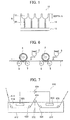
- FIG. 6 shows an aluminum plate 1, roller-type brushes (bristle bundle brushes in Examples) 2 and 4, an abrasive-containing slurry 3, and support rollers 5, 6, 7 and 8.
- the bristle bundle brushes were made of nylon 6/10 and had a bristle diameter of 0.3 mm and a bristle length of 50 mm.
- Each brush was constructed of a 300 mm diameter stainless steel cylinder in which holes had been formed and bristles densely set.
- Two support rollers 200 mm diameter were provided below each bristle bundle brush and spaced 300 mm apart. The bundle bristle brushes were pressed against the aluminum plate until the load on the driving motor that rotate the brushes was greater by 10 kW than before the bundle bristle brushes were pressed against the plate. The direction in which the brushes were rotated was the same as the direction in which the aluminum plate was moved.
- Etching treatment was performed by using a spray line to spray the aluminum plate obtained as described above with an aqueous solution having a sodium hydroxide concentration of 26 wt%, an aluminum ion concentration of 6.5 wt%, and a temperature of 70°C. The plate was then rinsed by spraying with water. The amount of dissolved aluminum was 10 g/m 2 .
- desmutting treatment was performed in an aqueous nitric acid solution.
- the nitric acid wastewater from the subsequent electrochemical graining treatment step was used for the aqueous nitric acid solution in desmutting treatment.
- the solution temperature was 35°C.
- Desmutting treatment was performed by spraying the plate with the desmutting solution for 3 seconds.
- Electrochemical graining treatment was consecutively performed by nitric acid electrolysis using a 60 Hz AC voltage.
- Aluminum nitrate was added to an aqueous solution containing 10.4 g/L of nitric acid at a temperature of 35°C to prepare an electrolytic solution having an adjusted aluminum ion concentration of 4.5 g/L, and the electrolytic solution was used in electrochemical graining treatment.
- the alternating current waveform was as shown in FIG. 4 and electrochemical graining treatment was performed for a period of time tp until the current reached a peak from zero of 0.8 ms, at a duty ratio of 1:1, using an alternating current having a trapezoidal waveform, and with a carbon electrode as the counter electrode.
- a ferrite was used for the auxiliary anodes.
- An electrolytic cell of the type shown in FIG. 5 was used.
- the current density at the current peak was 30 A/dm 2 .
- 5% was diverted to the auxiliary anodes.
- the amount of electricity (C/dm 2 ) which is the total amount of electricity when the aluminum plate serves as an anode, was 185 C/dm 2 .
- the plate was then rinsed by spraying with water.
- Etching treatment was performed by using a spray line to spray the aluminum plate obtained as described above with an aqueous solution having a sodium hydroxide concentration of 5 wt%, an aluminum ion concentration of 0.5 wt%, and a temperature of 50°C. The plate was then rinsed by spraying with water. The amount of dissolved aluminum was 0.5 g/m 2
- desmutting treatment was performed in an aqueous sulfuric acid solution.
- the aqueous sulfuric acid solution used in desmutting treatment was a solution having a sulfuric acid concentration of 170 g/L and an aluminum ion concentration of 5 g/L.
- the solution temperature was 60°C.
- Desmutting treatment was performed by spraying the plate with the desmutting solution for 3 seconds.
- Electrochemical graining treatment was consecutively performed by hydrochloric acid electrolysis using a 60 Hz AC voltage.
- Aluminum chloride was added to an aqueous solution containing 6.2 g/L of hydrochloric acid at a temperature of 35°C to prepare an electrolytic solution having an adjusted aluminum ion concentration of 4.5 g/L, and the electrolytic solution was used in electrochemical graining treatment.
- the alternating current waveform was as shown in FIG. 4 and electrochemical graining treatment was performed for a period of time tp until the current reached a peak from zero of 0.8 ms, at a duty ratio of 1:1, using an alternating current having a trapezoidal waveform, and with a carbon electrode as the counter electrode.
- a ferrite was used for the auxiliary anodes.
- An electrolytic cell of the type shown in FIG. 5 was used.
- the current density at the current peak was 25 A/dm 2 .
- the plate was then rinsed by spraying with water.
- Etching treatment was performed by using a spray line to spray the aluminum plate obtained as described above with an aqueous solution having a sodium hydroxide concentration of 5 wt%, an aluminum ion concentration of 0.5 wt%, and a temperature of 50°C. The plate was then rinsed by spraying with water. The amount of dissolved aluminum was 0.1 g/m 2 .
- desmutting treatment was performed in an aqueous sulfuric acid solution. More specifically, wastewater generated in the anodizing treatment step (aqueous solution containing 170 g/L of sulfuric acid and 5 g/L of aluminum ions dissolved therein) was used to perform desmutting treatment at a solution temperature of 35°C for seconds. Desmutting treatment was performed by spraying the plate with the desmutting solution for 3 seconds.
- wastewater generated in the anodizing treatment step aqueous solution containing 170 g/L of sulfuric acid and 5 g/L of aluminum ions dissolved therein
- the first anodizing treatment was performed by DC electrolysis using an anodizing apparatus of the structure as shown in FIG. 7 .
- the anodizing treatment was performed under the conditions shown in Table 1 to form the anodized film with a specified film thickness.
- Aqueous solutions of acids such as sulfuric acid, phosphoric acid and oxalic acid were used for the electrolytic solution.
- an aluminum plate 616 is transported as shown by arrows in FIG. 7 .
- the aluminum plate 616 is positively (+) charged by a power supply electrode 620 in a power supply cell 612 containing an electrolytic solution 618.
- the aluminum plate 616 is then transported upward by a roller 622 disposed in the power supply cell 612, turned downward on a nip roller 624 and transported toward an electrolytic cell 614 containing an electrolytic solution 626 to be turned to a horizontal direction by a roller 628.
- the aluminum plate 616 is negatively (-) charged by an electrolytic electrode 630 to form an anodized film on the plate surface.
- the aluminum plate 616 emerging from the electrolytic cell 614 is then transported to the section for the subsequent step.
- the roller 622, the nip roller 624 and the roller 628 constitute direction changing means, and the aluminum plate 616 is transported through the power supply cell 612 and the electrolytic cell 614 in a mountain shape and a reversed U shape by means of these rollers 622, 624 and 628.
- the power supply electrode 620 and the electrolytic electrode 630 are connected to a dc power supply 634.
- Pore-widening treatment was performed by immersing the anodized aluminum plate in an aqueous solution having a sodium hydroxide concentration of 5 wt%, an aluminum ion concentration of 0.5 wt%, and a temperature of 35°C under the conditions shown in Table 1. The plate was then rinsed by spraying with water.
- the second anodizing treatment was performed by DC electrolysis using an anodizing apparatus of the structure as shown in FIG. 7 .
- the anodizing treatment was performed under the conditions shown in Table 1 to form the anodized film with a specified film thickness.
- Aqueous solution of sulfuric acid was used for the electrolytic solution.
- silicate treatment was performed by dipping the plate into an aqueous solution containing 2.5 wt% of No. 3 sodium silicate at 50°C for 7 seconds. The amount of deposited silicon was 8.5 mg/m 2 . The plate was then rinsed by spraying with water.
- the average diameter of the large-diameter portions at the surface of the anodized film, the average diameter of the small-diameter portions at their communication position and the depth in the micropore-bearing anodized film after the second anodizing treatment step (1) are collectively shown in Table 2.
- the average diameter of the micropores were determined as follows: The surface of the support (surface of the anodized film) was taken by FE-SEM at a magnification of 150,000X to obtain four images, and in the resulting four images, the diameter of the micropores (including the large-diameter portions and small-diameter portions) was measured within an area of 400 x 600 nm 2 and the average of the measurements was calculated.
- the depth of the micropores were determined as follows: The cross-sectional surface of the support (anodized film) was taken by FE-SEM at a magnification of 150,000X, and in the resulting image, the depth of arbitrarily selected 25 micropores were measured and the average of the measurements was calculated.
- micropores having specified average diameter and depth were formed in the anodized aluminum film.
- an image recording layer-forming coating fluid was applied onto the thus formed undercoat by bar coating and dried in an oven at 100°C for 60 seconds to form an image recording layer having a coating weight after drying of 1.3 g/m 2 .
- the image recording layer-forming coating fluid was obtained by mixing with stirring the photosensitive solution and microgel fluid shown below just before use in application.
- Binder polymer (1) [its structure is shown below] 0.24 g * Infrared absorber (1) [its structure is shown below] 0.030 g * Radical polymerization initiator (1) [its structure is shown below] 0.162 g * Polymerizable compound, tris(acryloyloxyerhyl)isocyanurate (NK ester A-9300 available from Shin-nakamura Chemical Corporation) 0.192 g * Low-molecular-weight hydrophilic compound, tris(2-hydroxyethyl)isocyanurate 0.062 g * Low-molecular-weight hydrophilic compound (1) [its structure is shown below] 0.052 g * Sensitizer Phosphonium compound (1) [its structure is shown below] 0.055 g * Sensitizer Benzyl-dimethyl-octyl ammonium-PF 6 salt 0.018 g * Betaine derivative (C-1) 0.010 g Fluorosurfactant (1) (weight-average molecular weight: 10,000) [its structure is shown below]
- the binder polymer (1), the infrared absorber (1), the radical polymerization initiator (1), the phosphonium compounds (1), the low-molecular-weight hydrophilic compound (1) and the fluorosurfactant (1) have the structures represented by the following formulas:
- the microgel (1) was synthesized by the following procedure.
- oil phase component 10g of an adduct of trimethylolpropane with xylene diisocyanate (Takenate D-110N available from Mitsui Takeda Chemical Industries, Ltd.), 3.15 g of pentaerythritol triacrylate (SR444 available from Nippon Kayaku Co., Ltd.) and 0.1 g of Pionin A-41C (available from Takemoto Oil & Fat Co., Ltd.) were dissolved in 17 g of ethyl acetate.
- aqueous phase component 40 g of a 4 wt% aqueous solution of PVA-205 was prepared.
- the oil phase component and the aqueous phase component were mixed and emulsified in a homogenizer at 12,000 rpm for 10 minutes.
- the resulting emulsion was added to 25 g of distilled water and the mixture was stirred at room temperature for 30 minutes, then at 50°C for 3 hours.
- the thus obtained microgel fluid was diluted with distilled water so as to have a solids concentration of 15 wt% and used as the microgel (1).
- the average particle size of the microgel as measured by a light scattering method was 0.2 ⁇ m.
- a protective layer-forming coating fluid of the composition indicated below was applied onto the thus formed image recording layer by bar coating and dried in an oven at 120°C for 60 seconds to form a protective layer having a coating weight after drying of 0.15 g/m 2 , thereby obtaining a presensitized plate.
- the dispersion of the inorganic layered compound (1) was prepared by the following procedure.
- the resulting presensitized plate was exposed by Luxel PLATESETTER T-6000III from FUJIFILM Corporation equipped with an infrared semiconductor laser at an external drum rotation speed of 1,000 rpm, a laser power of 70% and a resolution of 2,400 dpi.
- the exposed image was set to contain a solid image and a 50% halftone chart of a 20 ⁇ m-dot FM screen.
- the resulting presensitized plate after exposure was mounted without a development process on the plate cylinder of a Lithrone 26 press available from Komori Corporation.
- a fountain solution Ecolity-2 (FUJIFILM Corporation) /tap water at a volume ratio of 2/98 and Values-G (N) black ink (Dainippon Ink & Chemicals, Inc.) were used.
- the fountain solution and the ink were supplied by the standard automatic printing start-up procedure on the Lithrone 26 to perform on-press development, and 100 impressions were printed on Tokubishi art paper (76.5 kg) at a printing speed of 10,000 impressions per hour.
- the on-press developability was evaluated as the number of sheets of printing paper required to reach the state in which not ink is transferred to halftone non-image areas after the completion of the on-press development of the unexposed areas of the 50% halftone chart on the printing press.
- the on-press developability was rated as "excellent” when the number of sheets was up to 20, "good” when the number of sheets was from 21 to 30, and “poor” when the number of sheets was 31 or more. The results are shown in Table 3.
- On-press development was performed on the same type of printing press by the same procedure as above and printing was further continued.
- the press life was evaluated by the number of impressions at the time when the decrease in density of a solid image became visually recognizable.
- the press life was rated "poor” when the number of impressions was less than 10,000, "fair” when the number of impressions was at least 10,000 but less than 20,000, "good” when the number of impressions was at least 20,000 but less than 30,000, and "excellent” when the number of impressions was 30,000 or more.
- the results are shown in Table 3. It is necessary for the evaluation results in Table 3 not to include "fair” and "poor.”
- the surface of the resulting lithographic printing plate support was subjected to a scratch test to evaluate the scratch resistance of the lithographic printing plate support.
- the scratch test was performed using a continuous loading scratching intensity tester (SB-53 manufactured by Shinto Scientific Co., Ltd.) while moving a sapphire needle with a diameter of 0.4 mm at a moving velocity of 10 cm/s at a load of 100 g.
- SB-53 manufactured by Shinto Scientific Co., Ltd.
- the lithographic printing plate support exhibiting excellent scratch resistance at a load of 100 g can suppress the scratches from transferring to the image recording layer when the presensitized plate prepared therefrom is mounted on the plate cylinder or superposed on another, thus reducing scumming in non-image areas.
- Table 3 revealed that lithographic printing plates in Examples 1 to 31 obtained by using the lithographic printing plate supports each having an anodized aluminum film in which micropores having specified average diameter and depth were formed, had a long press life, excellent deinking ability when left to stand, excellent on-press developability and excellent scratch resistance.
- the large-diameter portions were in a substantially hemispherical shape and the small-diameter portions were in a substantially straight tubular shape.
Landscapes
- Chemical & Material Sciences (AREA)
- Chemical Kinetics & Catalysis (AREA)
- Electrochemistry (AREA)
- Engineering & Computer Science (AREA)
- Materials Engineering (AREA)
- Metallurgy (AREA)
- Organic Chemistry (AREA)
- Printing Plates And Materials Therefor (AREA)
- Photosensitive Polymer And Photoresist Processing (AREA)
- Materials For Photolithography (AREA)
Applications Claiming Priority (2)
| Application Number | Priority Date | Filing Date | Title |
|---|---|---|---|
| JP2010019766 | 2010-01-29 | ||
| JP2011008775A JP5498403B2 (ja) | 2010-01-29 | 2011-01-19 | 平版印刷版用支持体、平版印刷版用支持体の製造方法、および平版印刷版原版 |
Publications (2)
| Publication Number | Publication Date |
|---|---|
| EP2353882A1 true EP2353882A1 (fr) | 2011-08-10 |
| EP2353882B1 EP2353882B1 (fr) | 2013-03-13 |
Family
ID=43618160
Family Applications (1)
| Application Number | Title | Priority Date | Filing Date |
|---|---|---|---|
| EP20110152492 Active EP2353882B1 (fr) | 2010-01-29 | 2011-01-28 | Support de plaque d'impression lithographique, son procédé de fabrication et plaque présensibilisée |
Country Status (2)
| Country | Link |
|---|---|
| EP (1) | EP2353882B1 (fr) |
| JP (1) | JP5498403B2 (fr) |
Cited By (20)
| Publication number | Priority date | Publication date | Assignee | Title |
|---|---|---|---|---|
| WO2013032780A1 (fr) * | 2011-08-31 | 2013-03-07 | Eastman Kodak Company | Précurseurs de plaque d'impression lithographique pour un développement sur presse |
| CN104487261A (zh) * | 2012-07-27 | 2015-04-01 | 富士胶片株式会社 | 平版印刷版用支撑体及其制造方法、以及平版印刷版原版 |
| WO2018160379A1 (fr) | 2017-03-02 | 2018-09-07 | Eastman Kodak Company | Précurseurs de plaque d'impression lithographique et procédé d'utilisation |
| CN109729714A (zh) * | 2017-08-31 | 2019-05-07 | 富士胶片株式会社 | 平版印刷版原版、平版印刷版的制造方法、印刷方法 |
| CN109863033A (zh) * | 2017-03-31 | 2019-06-07 | 富士胶片株式会社 | 平版印刷版原版及其制造方法、平版印刷版原版层叠体、平版印刷版的制版方法以及平版印刷方法 |
| US10363734B2 (en) | 2017-03-02 | 2019-07-30 | Eastman Kodak Company | Method for making lithographic printing plates |
| US10696083B2 (en) | 2017-03-31 | 2020-06-30 | Fujifilm Corporation | Lithographic printing plate precursor, method of producing same, lithographic printing plate precursor laminate, and lithographic printing method |
| WO2021055187A1 (fr) | 2019-09-17 | 2021-03-25 | Eastman Kodak Company | Précurseur de plaque d'impression lithographique et procédé d'utilisation |
| WO2021067054A1 (fr) | 2019-10-01 | 2021-04-08 | Eastman Kodak Company | Précurseurs de plaque d'impression lithographique et procédé d'utilisation |
| WO2021194741A1 (fr) | 2020-03-25 | 2021-09-30 | Eastman Kodak Company | Précurseur de plaque d'impression lithographique et procédé d'utilisation |
| WO2022051095A1 (fr) | 2020-09-04 | 2022-03-10 | Eastman Kodak Company | Précurseur de plaque d'impression lithographique et procédé d'utilisation |
| WO2022119719A1 (fr) | 2020-12-04 | 2022-06-09 | Eastman Kodak Company | Précurseurs de plaque d'impression lithographique et procédé d'utilisation |
| WO2022132444A1 (fr) | 2020-12-17 | 2022-06-23 | Eastman Kodak Company | Précurseurs de plaque d'impression lithographique et procédé d'utilisation |
| WO2023003712A1 (fr) | 2021-07-23 | 2023-01-26 | Eastman Kodak Company | Précurseur de plaque d'impression lithographique et procédé d'utilisation |
| CN115726014A (zh) * | 2023-01-13 | 2023-03-03 | 福建省永春双恒铝材有限公司 | 耐腐蚀铝型材的表面处理工艺 |
| WO2023167796A1 (fr) | 2022-03-03 | 2023-09-07 | Eastman Kodak Company | Précurseur de plaque d'impression lithographique et procédé d'utilisation |
| US11813884B2 (en) | 2020-12-17 | 2023-11-14 | Eastman Kodak Company | Lithographic printing plate precursors and method of use |
| WO2024035548A1 (fr) | 2022-08-12 | 2024-02-15 | Eastman Kodak Company | Précurseur de plaque d'impression lithographique et procédé d'utilisation |
| US11964466B2 (en) | 2020-10-21 | 2024-04-23 | Eastman Kodak Company | Lithographic printing plate precursors and method of use |
| WO2025006193A1 (fr) | 2023-06-27 | 2025-01-02 | Eastman Kodak Company | Précurseur de plaque d'impression lithographique, et procédé d'utilisation |
Families Citing this family (2)
| Publication number | Priority date | Publication date | Assignee | Title |
|---|---|---|---|---|
| WO2019064696A1 (fr) | 2017-09-29 | 2019-04-04 | 富士フイルム株式会社 | Plaque d'origine de plaque d'impression à plat, procédé de fabrication de plaque d'impression à plat, et procédé d'impression à plat |
| JP7590714B2 (ja) * | 2019-11-08 | 2024-11-27 | 株式会社サーテック永田 | アルミニウム合金成形品の製造方法、及びアルミニウム合金成形品を用いた接合品の製造方法 |
Citations (22)
| Publication number | Priority date | Publication date | Assignee | Title |
|---|---|---|---|---|
| US2714066A (en) | 1950-12-06 | 1955-07-26 | Minnesota Mining & Mfg | Planographic printing plate |
| US3181461A (en) | 1963-05-23 | 1965-05-04 | Howard A Fromson | Photographic plate |
| US3458311A (en) | 1966-06-27 | 1969-07-29 | Du Pont | Photopolymerizable elements with solvent removable protective layers |
| US3511661A (en) | 1966-07-01 | 1970-05-12 | Eastman Kodak Co | Lithographic printing plate |
| JPS4818327B1 (fr) | 1969-10-09 | 1973-06-05 | ||
| JPS4841708B1 (fr) | 1970-01-13 | 1973-12-07 | ||
| GB1412768A (en) | 1971-10-07 | 1975-11-05 | Fuji Photo Film Co Ltd | Process for producing a base plate for a photosensitive printing plate |
| JPS5040047B2 (fr) | 1971-09-06 | 1975-12-22 | ||
| JPS5549729B2 (fr) | 1973-02-07 | 1980-12-13 | ||
| JPH055005A (ja) | 1991-04-26 | 1993-01-14 | Kyowa Hakko Kogyo Co Ltd | 光重合開始剤およびこれを含有する光重合性組成物 |
| JPH05195300A (ja) | 1992-01-23 | 1993-08-03 | Fuji Photo Film Co Ltd | 電解処理装置 |
| JPH11291657A (ja) | 1998-04-15 | 1999-10-26 | Fuji Photo Film Co Ltd | 平版印刷版用支持体の製造方法 |
| JP2001133969A (ja) | 1999-11-01 | 2001-05-18 | Fuji Photo Film Co Ltd | ネガ型平版印刷版原版 |
| JP2001222101A (ja) | 2000-02-09 | 2001-08-17 | Mitsubishi Paper Mills Ltd | 感光性組成物および感光性平版印刷版材料 |
| JP2002023360A (ja) | 2000-07-12 | 2002-01-23 | Fuji Photo Film Co Ltd | ネガ型画像記録材料 |
| JP2002040638A (ja) | 2000-07-25 | 2002-02-06 | Fuji Photo Film Co Ltd | ネガ型画像記録材料及び画像形成方法 |
| JP2002278057A (ja) | 2001-01-15 | 2002-09-27 | Fuji Photo Film Co Ltd | ネガ型画像記録材料及びシアニン色素 |
| JP2003001956A (ja) | 2001-03-15 | 2003-01-08 | Fuji Photo Film Co Ltd | 平版印刷版用支持体および平版印刷版原版 |
| JP2005254638A (ja) | 2004-03-12 | 2005-09-22 | Fuji Photo Film Co Ltd | 平版印刷版用支持体の製造方法 |
| JP2007090850A (ja) | 2005-08-29 | 2007-04-12 | Fujifilm Corp | 平版印刷版原版、平版印刷方法、及び新規シアニン色素 |
| JP2008195018A (ja) | 2007-02-15 | 2008-08-28 | Fujifilm Corp | 平版印刷版原版および平版印刷方法 |
| JP2009255434A (ja) | 2008-04-18 | 2009-11-05 | Fujifilm Corp | 平版印刷版用アルミニウム合金板、平版印刷版用支持体、平版印刷版用原版および平版印刷版用アルミニウム合金板の製造方法 |
Family Cites Families (3)
| Publication number | Priority date | Publication date | Assignee | Title |
|---|---|---|---|---|
| JPH10264548A (ja) * | 1997-03-28 | 1998-10-06 | Mitsubishi Paper Mills Ltd | オフセット印刷版用アルミニウム支持体及び銀塩オフセット印刷原版 |
| JPH11174663A (ja) * | 1997-12-17 | 1999-07-02 | Konica Corp | 平版印刷版用支持体とその製造方法 |
| JP4195781B2 (ja) * | 2000-12-20 | 2008-12-10 | 富士フイルム株式会社 | 平版印刷版用原版 |
-
2011
- 2011-01-19 JP JP2011008775A patent/JP5498403B2/ja active Active
- 2011-01-28 EP EP20110152492 patent/EP2353882B1/fr active Active
Patent Citations (22)
| Publication number | Priority date | Publication date | Assignee | Title |
|---|---|---|---|---|
| US2714066A (en) | 1950-12-06 | 1955-07-26 | Minnesota Mining & Mfg | Planographic printing plate |
| US3181461A (en) | 1963-05-23 | 1965-05-04 | Howard A Fromson | Photographic plate |
| US3458311A (en) | 1966-06-27 | 1969-07-29 | Du Pont | Photopolymerizable elements with solvent removable protective layers |
| US3511661A (en) | 1966-07-01 | 1970-05-12 | Eastman Kodak Co | Lithographic printing plate |
| JPS4818327B1 (fr) | 1969-10-09 | 1973-06-05 | ||
| JPS4841708B1 (fr) | 1970-01-13 | 1973-12-07 | ||
| JPS5040047B2 (fr) | 1971-09-06 | 1975-12-22 | ||
| GB1412768A (en) | 1971-10-07 | 1975-11-05 | Fuji Photo Film Co Ltd | Process for producing a base plate for a photosensitive printing plate |
| JPS5549729B2 (fr) | 1973-02-07 | 1980-12-13 | ||
| JPH055005A (ja) | 1991-04-26 | 1993-01-14 | Kyowa Hakko Kogyo Co Ltd | 光重合開始剤およびこれを含有する光重合性組成物 |
| JPH05195300A (ja) | 1992-01-23 | 1993-08-03 | Fuji Photo Film Co Ltd | 電解処理装置 |
| JPH11291657A (ja) | 1998-04-15 | 1999-10-26 | Fuji Photo Film Co Ltd | 平版印刷版用支持体の製造方法 |
| JP2001133969A (ja) | 1999-11-01 | 2001-05-18 | Fuji Photo Film Co Ltd | ネガ型平版印刷版原版 |
| JP2001222101A (ja) | 2000-02-09 | 2001-08-17 | Mitsubishi Paper Mills Ltd | 感光性組成物および感光性平版印刷版材料 |
| JP2002023360A (ja) | 2000-07-12 | 2002-01-23 | Fuji Photo Film Co Ltd | ネガ型画像記録材料 |
| JP2002040638A (ja) | 2000-07-25 | 2002-02-06 | Fuji Photo Film Co Ltd | ネガ型画像記録材料及び画像形成方法 |
| JP2002278057A (ja) | 2001-01-15 | 2002-09-27 | Fuji Photo Film Co Ltd | ネガ型画像記録材料及びシアニン色素 |
| JP2003001956A (ja) | 2001-03-15 | 2003-01-08 | Fuji Photo Film Co Ltd | 平版印刷版用支持体および平版印刷版原版 |
| JP2005254638A (ja) | 2004-03-12 | 2005-09-22 | Fuji Photo Film Co Ltd | 平版印刷版用支持体の製造方法 |
| JP2007090850A (ja) | 2005-08-29 | 2007-04-12 | Fujifilm Corp | 平版印刷版原版、平版印刷方法、及び新規シアニン色素 |
| JP2008195018A (ja) | 2007-02-15 | 2008-08-28 | Fujifilm Corp | 平版印刷版原版および平版印刷方法 |
| JP2009255434A (ja) | 2008-04-18 | 2009-11-05 | Fujifilm Corp | 平版印刷版用アルミニウム合金板、平版印刷版用支持体、平版印刷版用原版および平版印刷版用アルミニウム合金板の製造方法 |
Non-Patent Citations (1)
| Title |
|---|
| "Senryo Binran", 1970, THE SOCIETY OF SYNTHETIC ORGANIC CHEMISTRY |
Cited By (31)
| Publication number | Priority date | Publication date | Assignee | Title |
|---|---|---|---|---|
| WO2013032780A1 (fr) * | 2011-08-31 | 2013-03-07 | Eastman Kodak Company | Précurseurs de plaque d'impression lithographique pour un développement sur presse |
| CN104487261A (zh) * | 2012-07-27 | 2015-04-01 | 富士胶片株式会社 | 平版印刷版用支撑体及其制造方法、以及平版印刷版原版 |
| US9259954B2 (en) | 2012-07-27 | 2016-02-16 | Fujifilm Corporation | Support for lithographic printing plate and manufacturing method therefor, as well as original lithographic printing plate |
| CN104487261B (zh) * | 2012-07-27 | 2016-08-24 | 富士胶片株式会社 | 平版印刷版用支撑体及其制造方法、以及平版印刷版原版 |
| US10363734B2 (en) | 2017-03-02 | 2019-07-30 | Eastman Kodak Company | Method for making lithographic printing plates |
| WO2018160379A1 (fr) | 2017-03-02 | 2018-09-07 | Eastman Kodak Company | Précurseurs de plaque d'impression lithographique et procédé d'utilisation |
| US10828884B2 (en) | 2017-03-02 | 2020-11-10 | Eastman Kodak Company | Lithographic printing plate precursors and method of use |
| CN109863033A (zh) * | 2017-03-31 | 2019-06-07 | 富士胶片株式会社 | 平版印刷版原版及其制造方法、平版印刷版原版层叠体、平版印刷版的制版方法以及平版印刷方法 |
| US10919331B2 (en) | 2017-03-31 | 2021-02-16 | Fujifilm Corporation | Lithographic printing plate precursor, method of producing same, lithographic printing plate precursor laminate, and lithographic printing method |
| CN109863033B (zh) * | 2017-03-31 | 2020-04-10 | 富士胶片株式会社 | 平版印刷版原版及其制造方法、平版印刷版原版层叠体、平版印刷版的制版方法以及平版印刷方法 |
| US10639924B2 (en) | 2017-03-31 | 2020-05-05 | Fujifilm Corporation | Lithographic printing plate precursor, method of producing same, lithographic printing plate precursor laminate, plate-making method for lithographic printing plate, and lithographic printing method |
| US10696083B2 (en) | 2017-03-31 | 2020-06-30 | Fujifilm Corporation | Lithographic printing plate precursor, method of producing same, lithographic printing plate precursor laminate, and lithographic printing method |
| US10800195B2 (en) | 2017-03-31 | 2020-10-13 | Fujifilm Corporation | Lithographic printing plate precursor, method of producing same, lithographic printing plate precursor laminate, and lithographic printing method |
| US11498353B2 (en) | 2017-03-31 | 2022-11-15 | Fujifilm Corporation | Lithographic printing plate precursor, method of producing same, lithographic printing plate precursor laminate, plate-making method for lithographic printing plate, and lithographic printing method |
| US10875346B2 (en) | 2017-08-31 | 2020-12-29 | Fujifilm Corporation | Lithographic printing plate precursor, lithographic printing plate manufacturing method and printing method |
| EP3476616A4 (fr) * | 2017-08-31 | 2019-07-10 | FUJIFILM Corporation | Cliché original de plaque d'impression à plat, procédé de production de plaque d'impression à plat, et procédé d'impression |
| CN109729714A (zh) * | 2017-08-31 | 2019-05-07 | 富士胶片株式会社 | 平版印刷版原版、平版印刷版的制造方法、印刷方法 |
| WO2021055187A1 (fr) | 2019-09-17 | 2021-03-25 | Eastman Kodak Company | Précurseur de plaque d'impression lithographique et procédé d'utilisation |
| WO2021067054A1 (fr) | 2019-10-01 | 2021-04-08 | Eastman Kodak Company | Précurseurs de plaque d'impression lithographique et procédé d'utilisation |
| WO2021194741A1 (fr) | 2020-03-25 | 2021-09-30 | Eastman Kodak Company | Précurseur de plaque d'impression lithographique et procédé d'utilisation |
| WO2022051095A1 (fr) | 2020-09-04 | 2022-03-10 | Eastman Kodak Company | Précurseur de plaque d'impression lithographique et procédé d'utilisation |
| US11964466B2 (en) | 2020-10-21 | 2024-04-23 | Eastman Kodak Company | Lithographic printing plate precursors and method of use |
| WO2022119719A1 (fr) | 2020-12-04 | 2022-06-09 | Eastman Kodak Company | Précurseurs de plaque d'impression lithographique et procédé d'utilisation |
| US11813884B2 (en) | 2020-12-17 | 2023-11-14 | Eastman Kodak Company | Lithographic printing plate precursors and method of use |
| WO2022132444A1 (fr) | 2020-12-17 | 2022-06-23 | Eastman Kodak Company | Précurseurs de plaque d'impression lithographique et procédé d'utilisation |
| WO2023003712A1 (fr) | 2021-07-23 | 2023-01-26 | Eastman Kodak Company | Précurseur de plaque d'impression lithographique et procédé d'utilisation |
| WO2023167796A1 (fr) | 2022-03-03 | 2023-09-07 | Eastman Kodak Company | Précurseur de plaque d'impression lithographique et procédé d'utilisation |
| WO2024035548A1 (fr) | 2022-08-12 | 2024-02-15 | Eastman Kodak Company | Précurseur de plaque d'impression lithographique et procédé d'utilisation |
| CN115726014A (zh) * | 2023-01-13 | 2023-03-03 | 福建省永春双恒铝材有限公司 | 耐腐蚀铝型材的表面处理工艺 |
| CN115726014B (zh) * | 2023-01-13 | 2023-04-28 | 福建省永春双恒铝材有限公司 | 耐腐蚀铝型材的表面处理工艺 |
| WO2025006193A1 (fr) | 2023-06-27 | 2025-01-02 | Eastman Kodak Company | Précurseur de plaque d'impression lithographique, et procédé d'utilisation |
Also Published As
| Publication number | Publication date |
|---|---|
| EP2353882B1 (fr) | 2013-03-13 |
| JP2011173413A (ja) | 2011-09-08 |
| JP5498403B2 (ja) | 2014-05-21 |
Similar Documents
| Publication | Publication Date | Title |
|---|---|---|
| EP2353882B1 (fr) | Support de plaque d'impression lithographique, son procédé de fabrication et plaque présensibilisée | |
| EP2520439B1 (fr) | Support pour plaque d'impression planographique, procédé de production de support pour plaque d'impression planographique, et plaque originale d'impression planographique | |
| US8978555B2 (en) | Lithographic printing plate support and presensitized plate | |
| EP2878452B1 (fr) | Support pour plaque d'impression lithographique et procédé pour sa fabrication | |
| EP2383125B1 (fr) | Support de plaque d'impression lithographique et plaque présensibilisée | |
| EP3476616B1 (fr) | Précurseur de plaque d'impression lithographique, procédé de fabrication de plaque d'impression lithographique et procédé d'impression | |
| EP2808173A1 (fr) | Support de plaque d'impression lithographique, procédé de fabrication de support de plaque d'impression lithographique et original de plaque d'impression lithographique | |
| JP5205480B2 (ja) | 平版印刷版用支持体、および平版印刷版原版 | |
| US10525696B2 (en) | Lithographic printing plate precursor, lithographic printing plate manufacturing method, printing method and aluminum support manufacturing method | |
| JP5498905B2 (ja) | 平版印刷版用支持体、平版印刷版用支持体の製造方法、および平版印刷版原版 | |
| JP5203477B2 (ja) | 平版印刷版用支持体、および平版印刷版原版 |
Legal Events
| Date | Code | Title | Description |
|---|---|---|---|
| PUAI | Public reference made under article 153(3) epc to a published international application that has entered the european phase |
Free format text: ORIGINAL CODE: 0009012 |
|
| AK | Designated contracting states |
Kind code of ref document: A1 Designated state(s): AL AT BE BG CH CY CZ DE DK EE ES FI FR GB GR HR HU IE IS IT LI LT LU LV MC MK MT NL NO PL PT RO RS SE SI SK SM TR |
|
| AX | Request for extension of the european patent |
Extension state: BA ME |
|
| 17P | Request for examination filed |
Effective date: 20111118 |
|
| 17Q | First examination report despatched |
Effective date: 20111214 |
|
| GRAP | Despatch of communication of intention to grant a patent |
Free format text: ORIGINAL CODE: EPIDOSNIGR1 |
|
| GRAS | Grant fee paid |
Free format text: ORIGINAL CODE: EPIDOSNIGR3 |
|
| GRAA | (expected) grant |
Free format text: ORIGINAL CODE: 0009210 |
|
| AK | Designated contracting states |
Kind code of ref document: B1 Designated state(s): AL AT BE BG CH CY CZ DE DK EE ES FI FR GB GR HR HU IE IS IT LI LT LU LV MC MK MT NL NO PL PT RO RS SE SI SK SM TR |
|
| REG | Reference to a national code |
Ref country code: GB Ref legal event code: FG4D |
|
| REG | Reference to a national code |
Ref country code: CH Ref legal event code: EP Ref country code: AT Ref legal event code: REF Ref document number: 600550 Country of ref document: AT Kind code of ref document: T Effective date: 20130315 |
|
| REG | Reference to a national code |
Ref country code: IE Ref legal event code: FG4D |
|
| REG | Reference to a national code |
Ref country code: DE Ref legal event code: R096 Ref document number: 602011001021 Country of ref document: DE Effective date: 20130508 |
|
| PG25 | Lapsed in a contracting state [announced via postgrant information from national office to epo] |
Ref country code: NO Free format text: LAPSE BECAUSE OF FAILURE TO SUBMIT A TRANSLATION OF THE DESCRIPTION OR TO PAY THE FEE WITHIN THE PRESCRIBED TIME-LIMIT Effective date: 20130613 Ref country code: ES Free format text: LAPSE BECAUSE OF FAILURE TO SUBMIT A TRANSLATION OF THE DESCRIPTION OR TO PAY THE FEE WITHIN THE PRESCRIBED TIME-LIMIT Effective date: 20130624 Ref country code: SE Free format text: LAPSE BECAUSE OF FAILURE TO SUBMIT A TRANSLATION OF THE DESCRIPTION OR TO PAY THE FEE WITHIN THE PRESCRIBED TIME-LIMIT Effective date: 20130313 Ref country code: BG Free format text: LAPSE BECAUSE OF FAILURE TO SUBMIT A TRANSLATION OF THE DESCRIPTION OR TO PAY THE FEE WITHIN THE PRESCRIBED TIME-LIMIT Effective date: 20130613 Ref country code: LT Free format text: LAPSE BECAUSE OF FAILURE TO SUBMIT A TRANSLATION OF THE DESCRIPTION OR TO PAY THE FEE WITHIN THE PRESCRIBED TIME-LIMIT Effective date: 20130313 |
|
| REG | Reference to a national code |
Ref country code: AT Ref legal event code: MK05 Ref document number: 600550 Country of ref document: AT Kind code of ref document: T Effective date: 20130313 |
|
| REG | Reference to a national code |
Ref country code: NL Ref legal event code: VDEP Effective date: 20130313 |
|
| REG | Reference to a national code |
Ref country code: LT Ref legal event code: MG4D |
|
| PG25 | Lapsed in a contracting state [announced via postgrant information from national office to epo] |
Ref country code: SI Free format text: LAPSE BECAUSE OF FAILURE TO SUBMIT A TRANSLATION OF THE DESCRIPTION OR TO PAY THE FEE WITHIN THE PRESCRIBED TIME-LIMIT Effective date: 20130313 Ref country code: GR Free format text: LAPSE BECAUSE OF FAILURE TO SUBMIT A TRANSLATION OF THE DESCRIPTION OR TO PAY THE FEE WITHIN THE PRESCRIBED TIME-LIMIT Effective date: 20130614 Ref country code: FI Free format text: LAPSE BECAUSE OF FAILURE TO SUBMIT A TRANSLATION OF THE DESCRIPTION OR TO PAY THE FEE WITHIN THE PRESCRIBED TIME-LIMIT Effective date: 20130313 Ref country code: LV Free format text: LAPSE BECAUSE OF FAILURE TO SUBMIT A TRANSLATION OF THE DESCRIPTION OR TO PAY THE FEE WITHIN THE PRESCRIBED TIME-LIMIT Effective date: 20130313 |
|
| PG25 | Lapsed in a contracting state [announced via postgrant information from national office to epo] |
Ref country code: HR Free format text: LAPSE BECAUSE OF FAILURE TO SUBMIT A TRANSLATION OF THE DESCRIPTION OR TO PAY THE FEE WITHIN THE PRESCRIBED TIME-LIMIT Effective date: 20130313 Ref country code: BE Free format text: LAPSE BECAUSE OF FAILURE TO SUBMIT A TRANSLATION OF THE DESCRIPTION OR TO PAY THE FEE WITHIN THE PRESCRIBED TIME-LIMIT Effective date: 20130313 Ref country code: RS Free format text: LAPSE BECAUSE OF FAILURE TO SUBMIT A TRANSLATION OF THE DESCRIPTION OR TO PAY THE FEE WITHIN THE PRESCRIBED TIME-LIMIT Effective date: 20130313 |
|
| PG25 | Lapsed in a contracting state [announced via postgrant information from national office to epo] |
Ref country code: SK Free format text: LAPSE BECAUSE OF FAILURE TO SUBMIT A TRANSLATION OF THE DESCRIPTION OR TO PAY THE FEE WITHIN THE PRESCRIBED TIME-LIMIT Effective date: 20130313 Ref country code: RO Free format text: LAPSE BECAUSE OF FAILURE TO SUBMIT A TRANSLATION OF THE DESCRIPTION OR TO PAY THE FEE WITHIN THE PRESCRIBED TIME-LIMIT Effective date: 20130313 Ref country code: AT Free format text: LAPSE BECAUSE OF FAILURE TO SUBMIT A TRANSLATION OF THE DESCRIPTION OR TO PAY THE FEE WITHIN THE PRESCRIBED TIME-LIMIT Effective date: 20130313 Ref country code: CZ Free format text: LAPSE BECAUSE OF FAILURE TO SUBMIT A TRANSLATION OF THE DESCRIPTION OR TO PAY THE FEE WITHIN THE PRESCRIBED TIME-LIMIT Effective date: 20130313 Ref country code: NL Free format text: LAPSE BECAUSE OF FAILURE TO SUBMIT A TRANSLATION OF THE DESCRIPTION OR TO PAY THE FEE WITHIN THE PRESCRIBED TIME-LIMIT Effective date: 20130313 Ref country code: PT Free format text: LAPSE BECAUSE OF FAILURE TO SUBMIT A TRANSLATION OF THE DESCRIPTION OR TO PAY THE FEE WITHIN THE PRESCRIBED TIME-LIMIT Effective date: 20130715 Ref country code: EE Free format text: LAPSE BECAUSE OF FAILURE TO SUBMIT A TRANSLATION OF THE DESCRIPTION OR TO PAY THE FEE WITHIN THE PRESCRIBED TIME-LIMIT Effective date: 20130313 Ref country code: IS Free format text: LAPSE BECAUSE OF FAILURE TO SUBMIT A TRANSLATION OF THE DESCRIPTION OR TO PAY THE FEE WITHIN THE PRESCRIBED TIME-LIMIT Effective date: 20130713 |
|
| PG25 | Lapsed in a contracting state [announced via postgrant information from national office to epo] |
Ref country code: PL Free format text: LAPSE BECAUSE OF FAILURE TO SUBMIT A TRANSLATION OF THE DESCRIPTION OR TO PAY THE FEE WITHIN THE PRESCRIBED TIME-LIMIT Effective date: 20130313 |
|
| PLBE | No opposition filed within time limit |
Free format text: ORIGINAL CODE: 0009261 |
|
| STAA | Information on the status of an ep patent application or granted ep patent |
Free format text: STATUS: NO OPPOSITION FILED WITHIN TIME LIMIT |
|
| PG25 | Lapsed in a contracting state [announced via postgrant information from national office to epo] |
Ref country code: DK Free format text: LAPSE BECAUSE OF FAILURE TO SUBMIT A TRANSLATION OF THE DESCRIPTION OR TO PAY THE FEE WITHIN THE PRESCRIBED TIME-LIMIT Effective date: 20130313 |
|
| 26N | No opposition filed |
Effective date: 20131216 |
|
| PG25 | Lapsed in a contracting state [announced via postgrant information from national office to epo] |
Ref country code: IT Free format text: LAPSE BECAUSE OF FAILURE TO SUBMIT A TRANSLATION OF THE DESCRIPTION OR TO PAY THE FEE WITHIN THE PRESCRIBED TIME-LIMIT Effective date: 20130313 |
|
| REG | Reference to a national code |
Ref country code: DE Ref legal event code: R097 Ref document number: 602011001021 Country of ref document: DE Effective date: 20131216 |
|
| PG25 | Lapsed in a contracting state [announced via postgrant information from national office to epo] |
Ref country code: LU Free format text: LAPSE BECAUSE OF FAILURE TO SUBMIT A TRANSLATION OF THE DESCRIPTION OR TO PAY THE FEE WITHIN THE PRESCRIBED TIME-LIMIT Effective date: 20140128 |
|
| REG | Reference to a national code |
Ref country code: CH Ref legal event code: PL |
|
| PG25 | Lapsed in a contracting state [announced via postgrant information from national office to epo] |
Ref country code: CH Free format text: LAPSE BECAUSE OF NON-PAYMENT OF DUE FEES Effective date: 20140131 Ref country code: LI Free format text: LAPSE BECAUSE OF NON-PAYMENT OF DUE FEES Effective date: 20140131 |
|
| REG | Reference to a national code |
Ref country code: FR Ref legal event code: ST Effective date: 20140930 |
|
| REG | Reference to a national code |
Ref country code: IE Ref legal event code: MM4A |
|
| PG25 | Lapsed in a contracting state [announced via postgrant information from national office to epo] |
Ref country code: FR Free format text: LAPSE BECAUSE OF NON-PAYMENT OF DUE FEES Effective date: 20140131 |
|
| PG25 | Lapsed in a contracting state [announced via postgrant information from national office to epo] |
Ref country code: IE Free format text: LAPSE BECAUSE OF NON-PAYMENT OF DUE FEES Effective date: 20140128 |
|
| PG25 | Lapsed in a contracting state [announced via postgrant information from national office to epo] |
Ref country code: MC Free format text: LAPSE BECAUSE OF FAILURE TO SUBMIT A TRANSLATION OF THE DESCRIPTION OR TO PAY THE FEE WITHIN THE PRESCRIBED TIME-LIMIT Effective date: 20130313 |
|
| PG25 | Lapsed in a contracting state [announced via postgrant information from national office to epo] |
Ref country code: MT Free format text: LAPSE BECAUSE OF FAILURE TO SUBMIT A TRANSLATION OF THE DESCRIPTION OR TO PAY THE FEE WITHIN THE PRESCRIBED TIME-LIMIT Effective date: 20130313 |
|
| PG25 | Lapsed in a contracting state [announced via postgrant information from national office to epo] |
Ref country code: SM Free format text: LAPSE BECAUSE OF FAILURE TO SUBMIT A TRANSLATION OF THE DESCRIPTION OR TO PAY THE FEE WITHIN THE PRESCRIBED TIME-LIMIT Effective date: 20130313 |
|
| PG25 | Lapsed in a contracting state [announced via postgrant information from national office to epo] |
Ref country code: CY Free format text: LAPSE BECAUSE OF FAILURE TO SUBMIT A TRANSLATION OF THE DESCRIPTION OR TO PAY THE FEE WITHIN THE PRESCRIBED TIME-LIMIT Effective date: 20130313 |
|
| PG25 | Lapsed in a contracting state [announced via postgrant information from national office to epo] |
Ref country code: HU Free format text: LAPSE BECAUSE OF FAILURE TO SUBMIT A TRANSLATION OF THE DESCRIPTION OR TO PAY THE FEE WITHIN THE PRESCRIBED TIME-LIMIT; INVALID AB INITIO Effective date: 20110128 Ref country code: TR Free format text: LAPSE BECAUSE OF FAILURE TO SUBMIT A TRANSLATION OF THE DESCRIPTION OR TO PAY THE FEE WITHIN THE PRESCRIBED TIME-LIMIT Effective date: 20130313 |
|
| PG25 | Lapsed in a contracting state [announced via postgrant information from national office to epo] |
Ref country code: MK Free format text: LAPSE BECAUSE OF FAILURE TO SUBMIT A TRANSLATION OF THE DESCRIPTION OR TO PAY THE FEE WITHIN THE PRESCRIBED TIME-LIMIT Effective date: 20130313 |
|
| PG25 | Lapsed in a contracting state [announced via postgrant information from national office to epo] |
Ref country code: AL Free format text: LAPSE BECAUSE OF FAILURE TO SUBMIT A TRANSLATION OF THE DESCRIPTION OR TO PAY THE FEE WITHIN THE PRESCRIBED TIME-LIMIT Effective date: 20130313 |
|
| P01 | Opt-out of the competence of the unified patent court (upc) registered |
Effective date: 20230515 |
|
| PGFP | Annual fee paid to national office [announced via postgrant information from national office to epo] |
Ref country code: GB Payment date: 20251204 Year of fee payment: 16 |
|
| PGFP | Annual fee paid to national office [announced via postgrant information from national office to epo] |
Ref country code: DE Payment date: 20251203 Year of fee payment: 16 |