EP2354257B1 - Düsenstock - Google Patents
Düsenstock Download PDFInfo
- Publication number
- EP2354257B1 EP2354257B1 EP11000894.3A EP11000894A EP2354257B1 EP 2354257 B1 EP2354257 B1 EP 2354257B1 EP 11000894 A EP11000894 A EP 11000894A EP 2354257 B1 EP2354257 B1 EP 2354257B1
- Authority
- EP
- European Patent Office
- Prior art keywords
- nozzle
- thermal insulation
- nozzle fitting
- insulation material
- compensator
- Prior art date
- Legal status (The legal status is an assumption and is not a legal conclusion. Google has not performed a legal analysis and makes no representation as to the accuracy of the status listed.)
- Active
Links
Images


Classifications
-
- C—CHEMISTRY; METALLURGY
- C21—METALLURGY OF IRON
- C21B—MANUFACTURE OF IRON OR STEEL
- C21B7/00—Blast furnaces
- C21B7/16—Tuyéres
-
- C—CHEMISTRY; METALLURGY
- C21—METALLURGY OF IRON
- C21B—MANUFACTURE OF IRON OR STEEL
- C21B7/00—Blast furnaces
- C21B7/04—Blast furnaces with special refractories
- C21B7/06—Linings for furnaces
-
- C—CHEMISTRY; METALLURGY
- C21—METALLURGY OF IRON
- C21B—MANUFACTURE OF IRON OR STEEL
- C21B7/00—Blast furnaces
- C21B7/16—Tuyéres
- C21B7/163—Blowpipe assembly
-
- F—MECHANICAL ENGINEERING; LIGHTING; HEATING; WEAPONS; BLASTING
- F27—FURNACES; KILNS; OVENS; RETORTS
- F27B—FURNACES, KILNS, OVENS OR RETORTS IN GENERAL; OPEN SINTERING OR LIKE APPARATUS
- F27B1/00—Shaft or like vertical or substantially vertical furnaces
- F27B1/10—Details, accessories or equipment specially adapted for furnaces of these types
- F27B1/12—Shells or casings; Supports therefor
- F27B1/14—Arrangements of linings
-
- F—MECHANICAL ENGINEERING; LIGHTING; HEATING; WEAPONS; BLASTING
- F27—FURNACES; KILNS; OVENS; RETORTS
- F27B—FURNACES, KILNS, OVENS OR RETORTS IN GENERAL; OPEN SINTERING OR LIKE APPARATUS
- F27B1/00—Shaft or like vertical or substantially vertical furnaces
- F27B1/10—Details, accessories or equipment specially adapted for furnaces of these types
- F27B1/16—Arrangements of tuyeres
-
- F—MECHANICAL ENGINEERING; LIGHTING; HEATING; WEAPONS; BLASTING
- F27—FURNACES; KILNS; OVENS; RETORTS
- F27D—DETAILS OR ACCESSORIES OF FURNACES, KILNS, OVENS OR RETORTS, IN SO FAR AS THEY ARE OF KINDS OCCURRING IN MORE THAN ONE KIND OF FURNACE
- F27D1/00—Casings; Linings; Walls; Roofs
- F27D1/0003—Linings or walls
- F27D1/0023—Linings or walls comprising expansion joints or means to restrain expansion due to thermic flows
-
- F—MECHANICAL ENGINEERING; LIGHTING; HEATING; WEAPONS; BLASTING
- F27—FURNACES; KILNS; OVENS; RETORTS
- F27D—DETAILS OR ACCESSORIES OF FURNACES, KILNS, OVENS OR RETORTS, IN SO FAR AS THEY ARE OF KINDS OCCURRING IN MORE THAN ONE KIND OF FURNACE
- F27D1/00—Casings; Linings; Walls; Roofs
- F27D1/0003—Linings or walls
- F27D1/0033—Linings or walls comprising heat shields, e.g. heat shields
-
- F—MECHANICAL ENGINEERING; LIGHTING; HEATING; WEAPONS; BLASTING
- F27—FURNACES; KILNS; OVENS; RETORTS
- F27D—DETAILS OR ACCESSORIES OF FURNACES, KILNS, OVENS OR RETORTS, IN SO FAR AS THEY ARE OF KINDS OCCURRING IN MORE THAN ONE KIND OF FURNACE
- F27D3/00—Charging; Discharging; Manipulation of charge
- F27D3/16—Introducing a fluid jet or current into the charge
-
- F—MECHANICAL ENGINEERING; LIGHTING; HEATING; WEAPONS; BLASTING
- F16—ENGINEERING ELEMENTS AND UNITS; GENERAL MEASURES FOR PRODUCING AND MAINTAINING EFFECTIVE FUNCTIONING OF MACHINES OR INSTALLATIONS; THERMAL INSULATION IN GENERAL
- F16L—PIPES; JOINTS OR FITTINGS FOR PIPES; SUPPORTS FOR PIPES, CABLES OR PROTECTIVE TUBING; MEANS FOR THERMAL INSULATION IN GENERAL
- F16L59/00—Thermal insulation in general
- F16L59/14—Arrangements for the insulation of pipes or pipe systems
- F16L59/147—Arrangements for the insulation of pipes or pipe systems the insulation being located inwardly of the outer surface of the pipe
Definitions
- the invention relates to a nozzle for introducing hot blast into a shaft furnace, in particular blast furnace, comprising at least one joint compensator, a nozzle manifold and a nozzle tip, each having a metallic outer structure, which is provided on its inner side facing the hot blast with a refractory inner lining, wherein the Joint compensator connected at one end to the nozzle manifold and connectable to the other end with a hot blast line.
- the invention further proposes a method for producing a nozzle block formed from at least one joint compensator, a nozzle manifold and a nozzle tip, with which hot blast can be introduced into a shaft furnace, in particular a blast furnace, after the first metallic outer structures for the joint compensator, the nozzle manifold and the nozzle tip are provided, which are then filled with a refractory material to produce a refractory inner lining.
- hot air In order to reduce the energy consumption during iron production by means of a shaft furnace, hot air, called hot blast in the metallurgical industry, is blown into a shaft furnace at a temperature in the range of about 1200 ° C. to 1350 ° C.
- hot blast in the metallurgical industry
- ambient air is heated to a desired and nearly constant temperature by means of a hot-air heater heated area.
- the hot blast generated in this way is fed to the shaft furnace via a hot blast line system.
- the hot blast first passes from the hot blast to a hot blast line of the hot blast line system which extends around it in a lower section of the shaft furnace. From this hot blast line, the hot blast is then guided to several circumferentially distributed around the shaft furnace arranged nozzle sticks, which are also referred to as hot blast nozzle sticks.
- the nozzle sticks have as terminations of the hot air duct system in each case a nozzle tip, which are usually connected in the region between the coal sack and the catch of the shaft furnace with this and partially pro
- the hot air duct system Due to the high temperatures of the hot blast, it is necessary to reduce energy losses and to increase the service life of the hot air duct system to provide said components of the system on their sides facing the hot blast with a heat-insulating, refractory inner lining. This is especially true for the nozzle sticks, which are each composed of a plurality of interconnected components. Before assembling these components to a nozzle assembly, it is necessary to provide the components individually with the refractory lining. According to the prior art, the refractory inner lining is usually arranged directly on the hot wind-facing inside of the metallic outer structure of such a component.
- the metallic outer structures are usually made of steel and are designed differently for the various components of a nozzle block.
- the metallic outer structure of the nozzle tip is formed substantially conical.
- the joint compensator for example, a tubular-shaped metallic outer structure.
- the nozzle assembly comprises a nozzle manifold, the metallic outer structure is constructed much more complex than the nozzle tip and the joint compensator.
- these different shaped, supporting metal parts of the nozzle block with the more general term "metallic external structure".
- the refractory lining of the hot blast pipe system and the nozzle block causes the temperature on the outer surface of the metal exterior structures to be reduced to about 300 ° C to 350 ° C. It can thus reduce energy losses. In addition, the safety in the work areas on the outside of the blast furnace is improved.
- the joint compensator is used to compensate for deformations of the hot air duct system that occur as a result of the thermal load.
- Articulating joints are usually equipped with cardan joints and bellows, which are arranged in transition areas to the other components of a nozzle block.
- cardan joints and bellows which are arranged in transition areas to the other components of a nozzle block.
- the refractory inner linings of the directly adjoining components bear as close as possible to each other.
- nozzle sticks Since nozzle sticks are exposed to the described high thermal loads, they must be worked up from time to time, that is provided with a new refractory lining.
- the removal of the spent refractory lining is usually done using rotary hammers and similar tools and is correspondingly expensive.
- damage to the sensitive elements of the Gelenkkompensatoren for example, on the bellows, and on the hot wind facing inside of the metallic outer structure occur.
- a nozzle assembly of the type mentioned above in that it has at least one thermal insulation element arranged at least in a partial area between the metallic outer structure and the refractory inner lining of the joint compensator, nozzle manifold and / or nozzle tip, which has a high-temperature-resistant thermal insulation material embedded in a covering wherein the envelope is formed as a foil, which consists essentially of plastic and the envelope largely dissolves during the intended use of the nozzle block.
- the arrangement according to the invention of the additional thermal insulation element between the metallic outer structure and the refractory inner lining of at least one component of the nozzle block causes the energy loss via the nozzle assembly to be further reduced.
- the temperature on the outside of the nozzle block or the surface of the metallic outer structure of its constituents according to the invention by about 100 ° C to 150 ° C over a conventional nozzle, i. without additional heat insulation element, can be reduced. This represents a significant energy saving, which can be represented in coke per ton of pig iron produced.
- the service life of the nozzle block is significantly increased by the lower thermal load of the metallic outer structures and the elements of the joint compensator. During the intended use of the nozzle assembly, the film burns and thus dissolves as far as possible.
- the plastic may be, for example, polyethylene or polyamide and a mixture thereof. Furthermore, a metallized plastic is also considered.
- the additional thermal insulation element weakens the bond between the metallic outer structure and the refractory lining, since the envelope largely dissolves during the intended use of the nozzle block, in particular burns. This makes it possible in comparison to nozzle sticks of the prior art with significantly less effort to remove the refractory inner lining during refurbishment of the nozzle block of the metallic outer structures. This results in a further cost reduction.
- thermal insulation elements are used for a nozzle, which are arranged at particularly sensitive points of the nozzle assembly, such as in the region of the Gelenkkompensators.
- the thermal insulation material has at least one inorganic, silicate substance.
- the inorganic, siliceous substance is a highly dispersive (pyrogenic) silica.
- Such inorganic, silicate substances have a very low thermal conductivity and thus serve to provide a thermal insulation element with excellent thermal insulation properties.
- a further advantageous embodiment of the invention provides that the thermal insulation material has at least one means for reducing the heat radiation transport within the thermal insulation material.
- Such agents are also referred to as opacifiers and serve to reduce the permeability of the thermal insulation material with respect to infrared radiation, wherein the opacifier can scatter and / or absorb infrared radiation.
- This embodiment is useful in the nozzle assembly according to the invention, since the thermal insulation properties of thermal insulation materials without the Addition of a clouding agent with increasing temperature deteriorate.
- the thermal insulation material is formed in powder form and pressed into a shaped body. Moldings with a wide variety of geometries can be produced in order to be able to adapt the insulation element ideally to its respective site of use.
- the shaped body is rod-shaped. It can also be provided to embed several moldings in a common enclosure. In particular, a plurality of rod-shaped moldings can be positioned parallel to each other at a small distance within the enclosure. If an envelope made of plastic is selected, then a flexible thermal insulation element can be formed, the shape of which can be easily adapted to its respective site of use while deforming.
- the thermal insulation material is evacuated and welded into the enclosure.
- evacuating the thermal insulation properties of the thermal insulation material and thus of the thermal insulation element are further improved by the proportion of heat transfer generated in the use of the thermal insulation element by convection within the thermal insulation material is reduced.
- Welding the compressed thermal insulation material into the enclosure further causes the thermal insulation element to reliably maintain its shape and physical properties during manufacture of the nozzle assembly.
- the thermal insulation element is glued to the metallic outer structure.
- a thermal insulation element can thus be connected in a simple manner with the respective metallic outer structure before attaching the refractory inner lining.
- a flexibly formed thermal insulation element can thus be easily and permanently positioned at its respective desired location.
- a method of the type mentioned above is further proposed according to the present invention at the respective hot air facing inside of the metallic outer structure of joint compensator, nozzle manifold and / or nozzle tip prior to pouring it with the refractory material at least one thermal element at least in a partial area is arranged on the inside, which is formed in advance by welding a powdered, compressed into a molding thermal insulation material in a sheath, which dissolves during the intended use of the nozzle block as much as possible.
- the method according to the invention is also associated with the advantages of energy saving and reduction of operating costs of a shaft furnace mentioned above with regard to the nozzle.
- a foil which is essentially formed from plastic is advantageously used as the envelope.
- the thermal insulation element is glued to the metallic outer structure.
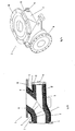
- FIG. 1a shows in perspective an exemplary embodiment of the nozzle tip 1 of a nozzle block according to the invention, not shown.
- the nozzle tip 1 When the nozzle tip 1 is used as intended, hot blast flows through it and exits from the outlet opening 2. At the other end, the nozzle tip 1 is connectable to the nozzle manifold 3 of the nozzle block, of which an exemplary embodiment in the FIGS. 2a and 2b is shown.
- Envelope 1 feeders 4 are arranged on the outside of the nozzle tip over which the combustion process in the shaft furnace optimizing substances are supplied to the hot blast stream.
- FIG. 1b shows a longitudinal section through the in FIG. 1a It can be seen the supporting, metallic outer structure 5, which is provided on its side facing the hot air inside with a refractory inner lining 6.
- a thermal insulation element 7 is arranged between the metallic outer structure 5 and the refractory inner lining 6.
- This heat-insulating element 7 has an unspecified, embedded in a cladding, high temperature resistant thermal insulation material, wherein the enclosure largely dissolves during the intended use of the nozzle block, in particular burns.
- the feeders 4 each have a feed channel 8 which extends through the refractory inner lining 6 and in the passage 9 of the nozzle tip. 1 empties.
- Figure 1c shows the nozzle tip 1 of FIGS. 1a and 1b in a longitudinal section along the line BB in FIG. 1b , It can be seen in particular the mouth of the feed channel 8 in the passageway 9. Furthermore, the construction according to the invention of the nozzle tip 1 can be seen, according to which a thermal insulation element 7 is arranged between the metallic outer structure 5 and the refractory inner lining 6.
- FIG. 2a shows in perspective an embodiment of the nozzle 3 of a nozzle block according to the invention.
- the nozzle manifold 3 is above the flange 10 with the joint compensator 15, as exemplified in FIG. 3 shown, connectable. With the flange 11 at the other end of the nozzle manifold 3 is connected to the nozzle tip 1.
- the nozzle manifold 3 has a branch 12, which is closed by a flap 13, which is pivotable about a hinge 14.
- FIG. 2b shows a longitudinal section through the in FIG. 2a It can be seen that the nozzle manifold 3 has the structure according to the invention, according to which a thermal insulation element 7 is arranged between the metallic outer structure 5 and the refractory inner lining 6.
- FIG. 3 shows an exploded view of an embodiment of a joint compensator 15 of the nozzle block.
- This can be connected via the flange 16 with the nozzle manifold 3.
- the flange 17 of the joint compensator 15 is connected to a hot blast line, not shown, a hot air duct system.
- the joint compensator 15 has not shown bellows.
- the middle piece 19, which likewise has a metallic outer structure 5 lined with refractory material, can be connected to the connecting piece 21 via the element 20 to form a universal joint.
- the element 20 also has a metallic outer structure 5 and a so equipped Fireproof interior lining 6 on.
- the joint compensator 15 also has a plurality of differently designed thermal insulation elements 7. These are formed according to the invention by an embedded in a cladding, refractory thermal insulation material.
- the envelope is given by a plastic film which includes a plurality of rod-shaped moldings of the thermal insulation material.
- the rod-shaped moldings are aligned parallel to each other and to the longitudinal extent of the Gelenkkompensators 15. They consist of a compressed to the moldings, powdery mixture of highly dispersible silica and a clouding agent.
- the heat-insulating elements 7 are designed to be flexible and can be adapted to the respective shaping of the other components of the joint compensator 15 at their respective destination without great expenditure of force.
- the plastic film burns due to the high temperatures and thus dissolves as much as possible.
Landscapes
- Engineering & Computer Science (AREA)
- Chemical & Material Sciences (AREA)
- Mechanical Engineering (AREA)
- General Engineering & Computer Science (AREA)
- Manufacturing & Machinery (AREA)
- Materials Engineering (AREA)
- Metallurgy (AREA)
- Organic Chemistry (AREA)
- Furnace Housings, Linings, Walls, And Ceilings (AREA)
- Structures Of Non-Positive Displacement Pumps (AREA)
Priority Applications (1)
| Application Number | Priority Date | Filing Date | Title |
|---|---|---|---|
| PL11000894T PL2354257T3 (pl) | 2010-02-05 | 2011-02-04 | Przewód kolanowy |
Applications Claiming Priority (1)
| Application Number | Priority Date | Filing Date | Title |
|---|---|---|---|
| DE102010007122A DE102010007122A1 (de) | 2010-02-05 | 2010-02-05 | Düsenstock |
Publications (2)
| Publication Number | Publication Date |
|---|---|
| EP2354257A1 EP2354257A1 (de) | 2011-08-10 |
| EP2354257B1 true EP2354257B1 (de) | 2014-11-26 |
Family
ID=44063539
Family Applications (1)
| Application Number | Title | Priority Date | Filing Date |
|---|---|---|---|
| EP11000894.3A Active EP2354257B1 (de) | 2010-02-05 | 2011-02-04 | Düsenstock |
Country Status (5)
| Country | Link |
|---|---|
| EP (1) | EP2354257B1 (sr) |
| DE (2) | DE102010007122A1 (sr) |
| ES (1) | ES2531179T3 (sr) |
| PL (1) | PL2354257T3 (sr) |
| RS (1) | RS53860B1 (sr) |
Family Cites Families (12)
| Publication number | Priority date | Publication date | Assignee | Title |
|---|---|---|---|---|
| GB235316A (en) * | 1924-03-14 | 1925-06-15 | Charles Henry Frost Bagley | Improvements in or relating to blast and like furnaces |
| US3069760A (en) * | 1958-06-11 | 1962-12-25 | United States Steel Corp | Ceramic coated tuyeres or the like |
| US3342473A (en) * | 1964-01-20 | 1967-09-19 | Jr Herbert A White | Apparatus for delivering air and fuel to a blast furnace |
| BE748939A (sr) * | 1969-04-21 | 1970-09-16 | Wurth Anciens Ets Paul | |
| AT346875B (de) * | 1974-09-06 | 1978-09-15 | Wurth Anciens Ets Paul | Kompensatorverbindung zwischen zwei mit feuerfestfutter versehenen rohrstuecken und gelenkduesenstoecke mit diesen verbindungen |
| LU70943A1 (sr) * | 1974-09-18 | 1975-03-06 | ||
| US4171798A (en) * | 1976-03-26 | 1979-10-23 | Koppers Company, Inc. | Method and apparatus for obtaining and securing optimum thrust of blast fluid flowing into a metallurgical furnace |
| AT373283B (de) * | 1982-04-05 | 1984-01-10 | Voest Alpine Ag | Duesenstock fuer einen schachtofen |
| US4572487A (en) * | 1984-05-10 | 1986-02-25 | Inland Steel Company | Blast furnace tuyere with replaceable liner |
| FR2601760B1 (fr) * | 1986-07-21 | 1990-05-04 | Siderurgie Fse Inst Rech | Busillon pour tuyere de haut fourneau |
| DE4136349C2 (de) * | 1991-11-05 | 2000-06-08 | Alois Gruber Ges M B H | Schweißvorrichtung für Kunststoffrohre |
| LU88241A1 (fr) * | 1993-03-31 | 1994-10-03 | Wurth Paul Sa | Dispositif d'injection d'air préchauffé dans un four à cuve |
-
2010
- 2010-02-05 DE DE102010007122A patent/DE102010007122A1/de not_active Withdrawn
-
2011
- 2011-02-04 PL PL11000894T patent/PL2354257T3/pl unknown
- 2011-02-04 EP EP11000894.3A patent/EP2354257B1/de active Active
- 2011-02-04 RS RS20150122A patent/RS53860B1/sr unknown
- 2011-02-04 DE DE202011102836U patent/DE202011102836U1/de not_active Expired - Lifetime
- 2011-02-04 ES ES11000894T patent/ES2531179T3/es active Active
Also Published As
| Publication number | Publication date |
|---|---|
| DE202011102836U1 (de) | 2011-11-16 |
| RS53860B1 (sr) | 2015-08-31 |
| PL2354257T3 (pl) | 2015-04-30 |
| EP2354257A1 (de) | 2011-08-10 |
| DE102010007122A1 (de) | 2011-08-11 |
| ES2531179T3 (es) | 2015-03-11 |
Similar Documents
| Publication | Publication Date | Title |
|---|---|---|
| DE202010018517U1 (de) | Metallaufnahmebehälter, die abgedichtete feuerfeste Verbindungen enthalten | |
| EP2427693A2 (de) | Isolierkassette | |
| DE2018875B2 (de) | Heisswindduesenstock fuer schacht-, insbesondere hochoefen | |
| DD240062A5 (de) | Isolierverfahren und feuerfestes material zur durchfuehrung des verfahrens | |
| EP0146079A2 (de) | Gasdurchlässiger Baukörper aus feuerfestem Material | |
| DE202012011622U1 (de) | Ausdehnungsverbindung für eine Fluidleitung | |
| EP2163800A2 (de) | Nachumhüllung des Verbindungsbereichs von mit Zementmörtel umhüllten Stahlrohrleitungen sowie eine derart nachumhüllte Stahlrohrleitung | |
| EP2354257B1 (de) | Düsenstock | |
| EP3569778A1 (de) | Verfahren zur herstellung eines bauelements sowie bauelement zur wärmebrückenarmen anbindung eines vorkragenden aussenteils an eine gebäudehülle | |
| DE3013560A1 (de) | Hochofen-korsettkuehlvorrichtung | |
| DE8118849U1 (de) | Waermedaemmende ummantelung fuer langgestreckte konstruktionsteile | |
| DE3724995A1 (de) | Verfahren zur herstellung eines verbundkoerpers und verbundkoerper selbst | |
| EP2876347B1 (de) | Dämmelement zur Wärme- und/ oder Schalldämmung von Rohren, insbesondere Kaminrohren | |
| DE3409386A1 (de) | Rauchgas fuehrendes rohr fuer schornsteine | |
| WO2016026986A1 (de) | Rohrleitung für heissgase und verfahren zu deren herstellung | |
| DE10223606B4 (de) | Vorrichtung zum Aufnehmen oder Führen einer Glasschmelze und Verfahren zum Anpassen des Wärmehaushalts der Vorrichtung | |
| DE8614864U1 (de) | Kamin mit geringem Wärmespeichervermögen | |
| DE3819086A1 (de) | Apparat fuer den leitungstransport von kraftwerksrauchgasen | |
| EP2542848B1 (de) | HEIßWINDDÜSENSTOCK FÜR EINEN SCHACHTOFEN, INSBESONDERE HOCHOFEN | |
| DE102004038479B4 (de) | Doppelwandiges Verbundrohr und Brandschutzformteil dafür | |
| DE4136649C2 (de) | Heißwinddüsenstock für Schachtöfen, insbesondere Hochöfen | |
| DE19623191C1 (de) | Rüssel für Entgasungsanlagen | |
| EP1403603B1 (de) | Anschlussleitung für ein Kühlelement für einen Schachtofen | |
| EP2987778A1 (de) | Isolierung für mit heissgas in berührung kommende teile einer schmalflächenbeschichtungsvorrichtung, insbesondere für schlauch- oder rohrförmige führungen für heissgas | |
| DE102007034426B3 (de) | Von einer Metallschmelze durchströmbares Bauteil eines Gießsystems |
Legal Events
| Date | Code | Title | Description |
|---|---|---|---|
| PUAI | Public reference made under article 153(3) epc to a published international application that has entered the european phase |
Free format text: ORIGINAL CODE: 0009012 |
|
| AK | Designated contracting states |
Kind code of ref document: A1 Designated state(s): AL AT BE BG CH CY CZ DE DK EE ES FI FR GB GR HR HU IE IS IT LI LT LU LV MC MK MT NL NO PL PT RO RS SE SI SK SM TR |
|
| AX | Request for extension of the european patent |
Extension state: BA ME |
|
| RIN1 | Information on inventor provided before grant (corrected) |
Inventor name: KRATZ, MARIO Inventor name: SCHWEICH, ROBERT Inventor name: WENER, MARCEL |
|
| 18W | Application withdrawn |
Effective date: 20110923 |
|
| D18W | Application withdrawn (deleted) | ||
| 17P | Request for examination filed |
Effective date: 20120202 |
|
| GRAP | Despatch of communication of intention to grant a patent |
Free format text: ORIGINAL CODE: EPIDOSNIGR1 |
|
| RIC1 | Information provided on ipc code assigned before grant |
Ipc: F27B 1/16 20060101ALI20140613BHEP Ipc: C21B 7/16 20060101AFI20140613BHEP Ipc: F27D 3/16 20060101ALI20140613BHEP Ipc: F27D 1/00 20060101ALI20140613BHEP Ipc: F27B 1/14 20060101ALI20140613BHEP Ipc: C21B 7/06 20060101ALI20140613BHEP |
|
| INTG | Intention to grant announced |
Effective date: 20140708 |
|
| GRAS | Grant fee paid |
Free format text: ORIGINAL CODE: EPIDOSNIGR3 |
|
| GRAA | (expected) grant |
Free format text: ORIGINAL CODE: 0009210 |
|
| AK | Designated contracting states |
Kind code of ref document: B1 Designated state(s): AL AT BE BG CH CY CZ DE DK EE ES FI FR GB GR HR HU IE IS IT LI LT LU LV MC MK MT NL NO PL PT RO RS SE SI SK SM TR |
|
| REG | Reference to a national code |
Ref country code: CH Ref legal event code: EP |
|
| REG | Reference to a national code |
Ref country code: AT Ref legal event code: REF Ref document number: 698269 Country of ref document: AT Kind code of ref document: T Effective date: 20141215 |
|
| REG | Reference to a national code |
Ref country code: IE Ref legal event code: FG4D Free format text: LANGUAGE OF EP DOCUMENT: GERMAN |
|
| REG | Reference to a national code |
Ref country code: DE Ref legal event code: R096 Ref document number: 502011005062 Country of ref document: DE Effective date: 20150108 |
|
| REG | Reference to a national code |
Ref country code: RO Ref legal event code: EPE |
|
| REG | Reference to a national code |
Ref country code: ES Ref legal event code: FG2A Ref document number: 2531179 Country of ref document: ES Kind code of ref document: T3 Effective date: 20150311 Ref country code: NL Ref legal event code: T3 |
|
| REG | Reference to a national code |
Ref country code: SE Ref legal event code: TRGR |
|
| REG | Reference to a national code |
Ref country code: LT Ref legal event code: MG4D |
|
| PG25 | Lapsed in a contracting state [announced via postgrant information from national office to epo] |
Ref country code: IS Free format text: LAPSE BECAUSE OF FAILURE TO SUBMIT A TRANSLATION OF THE DESCRIPTION OR TO PAY THE FEE WITHIN THE PRESCRIBED TIME-LIMIT Effective date: 20150326 Ref country code: PT Free format text: LAPSE BECAUSE OF FAILURE TO SUBMIT A TRANSLATION OF THE DESCRIPTION OR TO PAY THE FEE WITHIN THE PRESCRIBED TIME-LIMIT Effective date: 20150326 Ref country code: LT Free format text: LAPSE BECAUSE OF FAILURE TO SUBMIT A TRANSLATION OF THE DESCRIPTION OR TO PAY THE FEE WITHIN THE PRESCRIBED TIME-LIMIT Effective date: 20141126 |
|
| REG | Reference to a national code |
Ref country code: PL Ref legal event code: T3 |
|
| REG | Reference to a national code |
Ref country code: NO Ref legal event code: T2 Effective date: 20141126 |
|
| PG25 | Lapsed in a contracting state [announced via postgrant information from national office to epo] |
Ref country code: GR Free format text: LAPSE BECAUSE OF FAILURE TO SUBMIT A TRANSLATION OF THE DESCRIPTION OR TO PAY THE FEE WITHIN THE PRESCRIBED TIME-LIMIT Effective date: 20150227 Ref country code: LV Free format text: LAPSE BECAUSE OF FAILURE TO SUBMIT A TRANSLATION OF THE DESCRIPTION OR TO PAY THE FEE WITHIN THE PRESCRIBED TIME-LIMIT Effective date: 20141126 Ref country code: CY Free format text: LAPSE BECAUSE OF FAILURE TO SUBMIT A TRANSLATION OF THE DESCRIPTION OR TO PAY THE FEE WITHIN THE PRESCRIBED TIME-LIMIT Effective date: 20141126 Ref country code: HR Free format text: LAPSE BECAUSE OF FAILURE TO SUBMIT A TRANSLATION OF THE DESCRIPTION OR TO PAY THE FEE WITHIN THE PRESCRIBED TIME-LIMIT Effective date: 20141126 |
|
| REG | Reference to a national code |
Ref country code: SK Ref legal event code: T3 Ref document number: E 18194 Country of ref document: SK |
|
| PG25 | Lapsed in a contracting state [announced via postgrant information from national office to epo] |
Ref country code: DK Free format text: LAPSE BECAUSE OF FAILURE TO SUBMIT A TRANSLATION OF THE DESCRIPTION OR TO PAY THE FEE WITHIN THE PRESCRIBED TIME-LIMIT Effective date: 20141126 Ref country code: EE Free format text: LAPSE BECAUSE OF FAILURE TO SUBMIT A TRANSLATION OF THE DESCRIPTION OR TO PAY THE FEE WITHIN THE PRESCRIBED TIME-LIMIT Effective date: 20141126 |
|
| REG | Reference to a national code |
Ref country code: DE Ref legal event code: R097 Ref document number: 502011005062 Country of ref document: DE |
|
| REG | Reference to a national code |
Ref country code: HU Ref legal event code: AG4A Ref document number: E023902 Country of ref document: HU |
|
| REG | Reference to a national code |
Ref country code: CH Ref legal event code: PL |
|
| PLBE | No opposition filed within time limit |
Free format text: ORIGINAL CODE: 0009261 |
|
| STAA | Information on the status of an ep patent application or granted ep patent |
Free format text: STATUS: NO OPPOSITION FILED WITHIN TIME LIMIT |
|
| PG25 | Lapsed in a contracting state [announced via postgrant information from national office to epo] |
Ref country code: LI Free format text: LAPSE BECAUSE OF NON-PAYMENT OF DUE FEES Effective date: 20150228 Ref country code: CH Free format text: LAPSE BECAUSE OF NON-PAYMENT OF DUE FEES Effective date: 20150228 Ref country code: MC Free format text: LAPSE BECAUSE OF FAILURE TO SUBMIT A TRANSLATION OF THE DESCRIPTION OR TO PAY THE FEE WITHIN THE PRESCRIBED TIME-LIMIT Effective date: 20141126 |
|
| 26N | No opposition filed |
Effective date: 20150827 |
|
| REG | Reference to a national code |
Ref country code: IE Ref legal event code: MM4A |
|
| PG25 | Lapsed in a contracting state [announced via postgrant information from national office to epo] |
Ref country code: IE Free format text: LAPSE BECAUSE OF NON-PAYMENT OF DUE FEES Effective date: 20150204 |
|
| REG | Reference to a national code |
Ref country code: FR Ref legal event code: PLFP Year of fee payment: 6 |
|
| PG25 | Lapsed in a contracting state [announced via postgrant information from national office to epo] |
Ref country code: SI Free format text: LAPSE BECAUSE OF FAILURE TO SUBMIT A TRANSLATION OF THE DESCRIPTION OR TO PAY THE FEE WITHIN THE PRESCRIBED TIME-LIMIT Effective date: 20141126 |
|
| PG25 | Lapsed in a contracting state [announced via postgrant information from national office to epo] |
Ref country code: MT Free format text: LAPSE BECAUSE OF FAILURE TO SUBMIT A TRANSLATION OF THE DESCRIPTION OR TO PAY THE FEE WITHIN THE PRESCRIBED TIME-LIMIT Effective date: 20141126 |
|
| REG | Reference to a national code |
Ref country code: FR Ref legal event code: PLFP Year of fee payment: 7 |
|
| PG25 | Lapsed in a contracting state [announced via postgrant information from national office to epo] |
Ref country code: SM Free format text: LAPSE BECAUSE OF FAILURE TO SUBMIT A TRANSLATION OF THE DESCRIPTION OR TO PAY THE FEE WITHIN THE PRESCRIBED TIME-LIMIT Effective date: 20141126 |
|
| REG | Reference to a national code |
Ref country code: FR Ref legal event code: PLFP Year of fee payment: 8 |
|
| PG25 | Lapsed in a contracting state [announced via postgrant information from national office to epo] |
Ref country code: MK Free format text: LAPSE BECAUSE OF FAILURE TO SUBMIT A TRANSLATION OF THE DESCRIPTION OR TO PAY THE FEE WITHIN THE PRESCRIBED TIME-LIMIT Effective date: 20141126 |
|
| PG25 | Lapsed in a contracting state [announced via postgrant information from national office to epo] |
Ref country code: AL Free format text: LAPSE BECAUSE OF FAILURE TO SUBMIT A TRANSLATION OF THE DESCRIPTION OR TO PAY THE FEE WITHIN THE PRESCRIBED TIME-LIMIT Effective date: 20141126 |
|
| P01 | Opt-out of the competence of the unified patent court (upc) registered |
Effective date: 20230420 |
|
| PGFP | Annual fee paid to national office [announced via postgrant information from national office to epo] |
Ref country code: BG Payment date: 20250221 Year of fee payment: 15 |
|
| PGFP | Annual fee paid to national office [announced via postgrant information from national office to epo] |
Ref country code: PL Payment date: 20250127 Year of fee payment: 15 Ref country code: CZ Payment date: 20250127 Year of fee payment: 15 |
|
| PGFP | Annual fee paid to national office [announced via postgrant information from national office to epo] |
Ref country code: SK Payment date: 20250128 Year of fee payment: 15 |
|
| PGFP | Annual fee paid to national office [announced via postgrant information from national office to epo] |
Ref country code: ES Payment date: 20250331 Year of fee payment: 15 |
|
| PGFP | Annual fee paid to national office [announced via postgrant information from national office to epo] |
Ref country code: LU Payment date: 20260218 Year of fee payment: 16 Ref country code: NL Payment date: 20260218 Year of fee payment: 16 |
|
| PGFP | Annual fee paid to national office [announced via postgrant information from national office to epo] |
Ref country code: HU Payment date: 20260220 Year of fee payment: 16 |
|
| PGFP | Annual fee paid to national office [announced via postgrant information from national office to epo] |
Ref country code: SE Payment date: 20260218 Year of fee payment: 16 |
|
| PGFP | Annual fee paid to national office [announced via postgrant information from national office to epo] |
Ref country code: GB Payment date: 20260219 Year of fee payment: 16 |
|
| PGFP | Annual fee paid to national office [announced via postgrant information from national office to epo] |
Ref country code: NO Payment date: 20260220 Year of fee payment: 16 Ref country code: DE Payment date: 20260218 Year of fee payment: 16 |
|
| PGFP | Annual fee paid to national office [announced via postgrant information from national office to epo] |
Ref country code: AT Payment date: 20260219 Year of fee payment: 16 |
|
| PGFP | Annual fee paid to national office [announced via postgrant information from national office to epo] |
Ref country code: BE Payment date: 20260218 Year of fee payment: 16 Ref country code: RO Payment date: 20260127 Year of fee payment: 16 Ref country code: FI Payment date: 20260226 Year of fee payment: 16 Ref country code: IT Payment date: 20260224 Year of fee payment: 16 |
|
| PGFP | Annual fee paid to national office [announced via postgrant information from national office to epo] |
Ref country code: RS Payment date: 20260123 Year of fee payment: 16 |
|
| PGFP | Annual fee paid to national office [announced via postgrant information from national office to epo] |
Ref country code: FR Payment date: 20260218 Year of fee payment: 16 |
|
| PGFP | Annual fee paid to national office [announced via postgrant information from national office to epo] |
Ref country code: TR Payment date: 20260128 Year of fee payment: 16 |