EP2354335A1 - Dispositif sanitaire encastré doté d'un élément d'habillage associé - Google Patents
Dispositif sanitaire encastré doté d'un élément d'habillage associé Download PDFInfo
- Publication number
- EP2354335A1 EP2354335A1 EP11000426A EP11000426A EP2354335A1 EP 2354335 A1 EP2354335 A1 EP 2354335A1 EP 11000426 A EP11000426 A EP 11000426A EP 11000426 A EP11000426 A EP 11000426A EP 2354335 A1 EP2354335 A1 EP 2354335A1
- Authority
- EP
- European Patent Office
- Prior art keywords
- sanitary
- attachment sleeve
- cover plate
- plasters
- cladding element
- Prior art date
- Legal status (The legal status is an assumption and is not a legal conclusion. Google has not performed a legal analysis and makes no representation as to the accuracy of the status listed.)
- Granted
Links
Images



Classifications
-
- E—FIXED CONSTRUCTIONS
- E03—WATER SUPPLY; SEWERAGE
- E03C—DOMESTIC PLUMBING INSTALLATIONS FOR FRESH WATER OR WASTE WATER; SINKS
- E03C1/00—Domestic plumbing installations for fresh water or waste water; Sinks
- E03C1/12—Plumbing installations for waste water; Basins or fountains connected thereto; Sinks
- E03C1/28—Odour seals
-
- E—FIXED CONSTRUCTIONS
- E03—WATER SUPPLY; SEWERAGE
- E03C—DOMESTIC PLUMBING INSTALLATIONS FOR FRESH WATER OR WASTE WATER; SINKS
- E03C1/00—Domestic plumbing installations for fresh water or waste water; Sinks
- E03C1/12—Plumbing installations for waste water; Basins or fountains connected thereto; Sinks
- E03C1/32—Holders or supports for basins
- E03C2001/321—Siphon or angle valve covers
-
- E—FIXED CONSTRUCTIONS
- E03—WATER SUPPLY; SEWERAGE
- E03C—DOMESTIC PLUMBING INSTALLATIONS FOR FRESH WATER OR WASTE WATER; SINKS
- E03C2201/00—Details, devices or methods not otherwise provided for
- E03C2201/50—Constructional features of escutcheons for domestic plumbing installations
Definitions
- the invention relates to a sanitary flushing device with a flush-mounted siphon, as well as with a cladding element for covering an access opening of the flush-mounted siphon.
- a flush-mounted siphon is intended under plaster, especially behind a wall of a sanitary room, e.g. a bathroom or washroom mounted.
- Concealed siphons are currently used predominantly as an odor trap for washing or dishwasher outlets.
- a flush-mounted siphon is usually provided with a connecting piece, which projects through a wall opening in the stem wall.
- a flush-mounted siphon in addition to cleaning and repair purposes on an access opening or access opening, which is also accessible through the wall opening.
- the wall opening must therefore, as a rule, be dimensioned larger than would be necessary for the implementation of the connection piece.
- a flush-mounted siphon is usually associated with a cladding element, which is essentially formed by a cover plate.
- the connecting piece is usually provided with an external thread on the end of a hose nozzle is screwed with an associated locknut.
- the cover plate is in this case provided with a passage, with which the cover plate - before attachment of the hose connection - is pushed onto the connection piece. With the or another lock nut, the cover plate is screwed against the stem wall.
- the invention has for its object to form a sanitary flushing device with a concealed siphon and an associated cover plate to the effect that it is suitable for the inclusion of a washstand or a similar sanitary object.
- the Unterputz uncomfortable should in this case be particularly easy to install.
- the sanitary flushing device comprises a flush-mounted siphon with a non-threaded connection piece.
- the connecting piece is provided and designed in particular for receiving an outlet pipe to be connected and a seal sealing the outlet pipe with the flush-mounted siphon.
- the flush-mounted siphon further comprises an access or inspection opening, which is accessible in the intended installation state of the flush-mounted siphon through a wall opening of an upstream wall of the stem.
- the flush-mounted siphon additionally comprises a cladding element.
- This comprises a cover plate covering the access opening as intended, into which a passage for the outlet pipe has been introduced, as well as an attachment sleeve substantially flush with the passage on the cover plate and thus encircling the passage.
- the attachment sleeve is used to preciselystecken the cladding element to form an at least axially acting frictional engagement on the connection piece.
- the attachment sleeve projects into the wall opening, while the cover plate rests flat against the inner side of the front wall facing the interior.
- the so-designed flushing device is on the one hand suitable for connection of an outlet pipe of a washstand.
- the assembly of the cladding element is merely merely clipping on the cladding element, the sub-luting device is also particularly easy to install.
- the flushing device on a cladding element wherein the attachment sleeve is glued to the cover plate.
- the bonding of the cover plate with the Aufsteckmuffe is particularly advantageous in a preferred embodiment, in which the cover plate made of metal, in particular stainless steel.
- the attachment sleeve is - especially in the latter embodiment, but also independent of this - preferably made of a polar plastic, in particular acrylonitrile-butadiene-styrene (ABS) or polyamide (PA), which contributes to a good adhesive effect.
- a cold-crosslinking adhesive preferably a silicone or polyurethane adhesive (PUR) is used for bonding.
- PUR polyurethane adhesive
- attachment sleeve and / or the cover plate in the region of their respective adhesive surface with grooves or other structures.
- the cover plate is elongated, in particular substantially rectangular, whereby a comparatively large wall opening can be covered.
- an embodiment has proven to be advantageous in which the implementation is introduced eccentrically in the cover plate.
- At least one essentially axially aligned recess is introduced into the attachment sleeve.
- This or each recess is in particular directly from the end facing away from the cover plate of the attachment sleeve.
- this increases the radial flexibility of the attachment sleeve, in particular if a plurality of slots are made in the attachment sleeve, whereby a simple assembly of the lining element is achieved with good grip on the connection piece.
- At least one of the recesses corresponds to a radially projecting from the connecting piece projection, so that the cladding element against rotation with the formation of a tangential acting positive engagement on the connecting piece is placed.
- two, in particular opposite, recesses and projections are provided.
- each of the radially projecting projections is formed by a web which is formed in cross-section L- or T-shaped. During proper assembly then the web engages through the associated - in this case forcibly slot-shaped recess of the attachment sleeve radially through and undercuts the attachment sleeve on the outside. This causes a particularly good grip.
- two diametrically opposed slots are each flanked on both sides by two further slots in the attachment sleeve, while only two diametrically opposite corresponding projections are attached to the connecting piece.
- the central slots serve primarily the rotation
- the lateral slots serve primarily to improve the radial flexibility of the attachment sleeve. But they also also allow to put the cladding element in two defined inclinations on the connecting piece.
- the cover plate at the edge of the implementation of at least one tooth-like projection (hereinafter referred to as tooth), in the assembled state the cladding element engages with (in each case) a complementary recess in the attachment sleeve to form a positive connection.
- tooth a tooth-like projection
- the edge of the passage in the manner of a collar train in (relative to the implementation) axial direction is bent, so that the or each tooth protrudes from the cover plate in the axial direction.
- the toothing allows the attachment sleeve can be mounted only in a certain rotational position relative to the cover plate to this, resulting in a significant simplification of the production process.
- a plurality of teeth and recesses are arranged along the edge in an asymmetrical pattern.
- the flush-mounted siphon is preferably made of plastic, in particular polyethylene (PE).
- PE polyethylene
- the sanitary flushing device additionally comprises a substantially tubular extension adapter, which essentially serves to extend the connecting piece.
- the extension adapter is formed at its first end in an analogous manner with the attachment sleeve and is correspondingly like this or instead of this placed on the connection piece.
- the designed according to the type of attachment sleeve end of the extension adapter is also referred to below as Aufsteckabêt.
- At its second end of the extension adapter is formed in an analogous manner with the connecting piece, so that the attachment sleeve can be placed on this second, hereinafter referred to as the insertion end.
- the "analogous training" of Aufsteckabitess with the attachment sleeve or the Einsteckabitess with the connection piece is in this case given when the Aufsteckabêt is plugged onto the connecting piece under sufficient Reib gleich Struktur or if the insertion is inserted into the attachment sleeve under sufficient Reib gleich Struktur.
- the slip-on portion and the insertion portion are constructed in the same way as the attachment sleeve or the connection nozzle.
- the plug-in behavior the structure of the Aufsteckabites and the insertion of the structure of the attachment sleeve or the connecting piece but may differ substantially.
- the extension adapter can only be provided with two slots, while the attachment sleeve is provided with six slots as described above.
- the extension adapter is used in a preferred embodiment only for extending the connecting piece or for holding the cladding element, but has no sealing function.
- An outlet pipe to be connected is passed through the extension adapter, and sealingly received in the connection piece as in an embodiment without an extension adapter.
- the "connecting piece-like" insertion end is deliberately designed to be longer than necessary and is intended to be lengthened (sawed off) during assembly to a predetermined length dictated by the installation situation.
- the extension adapter is purposefully cut to length in such a way that it terminates approximately flush with the stem wall. It would also be conceivable, however, to design the connecting piece itself longer than necessary and cut it to the necessary level during assembly.
- the extension adapter To be able to cut the extension adapter to any desired length, it preferably has a profile which is constant over its length in the region of its insertion section.
- Fig. 1 shows a sanitary sub-plasters 1, which comprises a flush-mounted siphon 2, as well as a cladding element 3.
- the Unterputz Ran 2 shown here serves as a waste water connection for a washstand, not shown, which is connected by means of an outlet pipe 4.
- the flush-mounted siphon 2 is in a conventional manner behind a stem wall 5, while the cladding element 3 is arranged in front of the stem wall 5 and thus inside a sanitary room.
- a "sanitary room” is here in general any water-connecting building space called, in particular a bathroom.
- the flush-mounted siphon 2 made of PE essentially comprises a siphon housing 6, a connection pipe 7 on the inlet side, and a drain pipe 8 on the outlet side.
- the siphon housing 6 accommodates an internal structure which is not further explained here and acts as an odor trap, at least during operation of the flush-mounted siphon 2.
- the drain pipe 8 is integrally formed on a bottom 9 of the siphon housing.
- the connecting piece 7 is formed on one of the front wall 5 facing front side 10 to the siphon housing 6.
- the connecting piece 7 receives the outlet pipe 4 to form a sealing connection.
- bottom and front and the corresponding terms “bottom” and “front”, as well as the resulting opposite terms above and behind refer to the intended orientation of the flush-mounted siphon 2 and are used below regardless of its actual position in the surrounding space. In particular, these terms are also used for all intended as attached to the flush-mounted siphon 2 or components to be mounted.
- a closing with a screw cap access opening 11 is inserted into the siphon housing 6 for repair and / or cleaning purposes.
- a wall opening 12 is made in the stem wall 5. This wall opening 12 is covered by the cladding element 3.
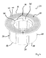
- the cladding element 3 is essentially formed by a rectangular cover plate 20 made of stainless steel, as well as an attachment sleeve 21 made of ABS.
- the cover plate 20 is dimensioned such that it projects beyond the wall opening 12 and thus can cover. At its outer edge 22, the cover plate 20 is rounded in particular to avoid sharp edges both at their corners and transversely to their plane to a - in the assembled state as intended the stem wall 5 facing - back 23 bent down.
- the attachment sleeve 21 is glued to the back 23 of the cover plate 20, wherein it surrounds a round with respect to their vertical extension eccentrically introduced into the cover plate 20 round implementation 24.
- the attachment sleeve 21 is essentially formed by a tubular piece 25, on the first flange-like end 26 of which an adhesive surface 27 is integrally formed, which protrudes radially beyond the tube piece 25 both inwardly and outwardly. At this adhesive surface 27, the attachment sleeve 21 is glued to the cover plate 20 with a silicone adhesive.
- Fig. 3 It can be seen that two opposite projections are integrally formed on the connecting piece 7 radially on the outside, which are formed here as webs 30.
- the webs 30 extend approximately in the axial direction of the connecting piece 7.
- the projections 30 are each approximately T-shaped, wherein each projection comprises an inner radial part 31 and an outer tangential part 32.
- the cladding element 3 is attached to the connecting piece 7 such that the webs 30 each engage with the radial part 31 in one of the mounting slots 29, each tangential part 32 rests radially on the outside of the attachment sleeve 21 and thereby acts stabilizing.
- the attachment sleeve 21 is glued so on the cover plate 20 during assembly of the cladding element 3, that the mounting slots 29 are arranged approximately on the longitudinal axis of the cover plate 20.
- a plurality of bulges of the cover plate 20 are bent approximately at right angles to the rear side 23 to form a plurality of teeth 34.
- these teeth 34 engage in complementary recesses 35, which are introduced on the inner edge 36 of the attachment sleeve 21.
- the teeth 34 or recesses 35 are arranged such that the mounting slots 29 are at their intended position.
- Both mounting slots 29 are flanked by two spring slots 37 on both sides. These spring slots 37 are actually used to increase the flexibility of the attachment sleeve 21.
- the cladding element 3 can also be pushed onto the connecting piece 7 as required so that webs 30 engage in two opposing slots 37. The cladding element 3 can thus be attached to the flush-mounted siphon in two defined inclinations.
- FIG. 4 the attachment sleeve 21 is shown in a pre-assembly state prior to bonding with the cover plate 20. From this representation, it can be seen that the attachment sleeve 21 in the region of the adhesive surface 27 is uniformly provided with a plurality of concentric grooves 40, which improve the adhesive effect of the adhesive bond.
- Fig. 5 is - again in the intended installation situation - a second embodiment of the flushing device shown.
- This second embodiment corresponds substantially to the first embodiment, but additionally includes an extension adapter 50.
- the extension adapter 50 is interposed between the connecting piece 7 and the cladding element 3, wherein the outlet tube 4 is passed through the extension adapter 50 therethrough.
- the extension adapter 50 is essentially formed by a tubular piece 51, which is formed at its first end 52 in a Aufsteckabexcellent analogous to the attachment sleeve 21 and is formed at its second end 53 in a male portion substantially analogous to the connecting piece 7. Accordingly, in the pipe section 51 at its first end 52 two mounting slots 54 are introduced.
Landscapes
- Engineering & Computer Science (AREA)
- Environmental & Geological Engineering (AREA)
- Health & Medical Sciences (AREA)
- Life Sciences & Earth Sciences (AREA)
- Hydrology & Water Resources (AREA)
- Public Health (AREA)
- Water Supply & Treatment (AREA)
- Sink And Installation For Waste Water (AREA)
Applications Claiming Priority (1)
| Application Number | Priority Date | Filing Date | Title |
|---|---|---|---|
| DE201020001240 DE202010001240U1 (de) | 2010-01-21 | 2010-01-21 | Sanitäre Unterputzeinrichtung mit zugehörigem Verkleidungselement |
Publications (3)
| Publication Number | Publication Date |
|---|---|
| EP2354335A1 true EP2354335A1 (fr) | 2011-08-10 |
| EP2354335B1 EP2354335B1 (fr) | 2014-12-24 |
| EP2354335B8 EP2354335B8 (fr) | 2015-03-11 |
Family
ID=42194522
Family Applications (1)
| Application Number | Title | Priority Date | Filing Date |
|---|---|---|---|
| EP20110000426 Active EP2354335B8 (fr) | 2010-01-21 | 2011-01-20 | Dispositif sanitaire encastré doté d'un élément d'habillage associé |
Country Status (2)
| Country | Link |
|---|---|
| EP (1) | EP2354335B8 (fr) |
| DE (1) | DE202010001240U1 (fr) |
Families Citing this family (1)
| Publication number | Priority date | Publication date | Assignee | Title |
|---|---|---|---|---|
| DE202020100660U1 (de) * | 2020-02-07 | 2020-03-02 | Angela Haas | Unterputzsiphon |
Citations (3)
| Publication number | Priority date | Publication date | Assignee | Title |
|---|---|---|---|---|
| DE3447098C1 (de) * | 1984-12-22 | 1986-03-20 | Helmuth Dallmer oHG, 5760 Arnsberg | Unterputz-Siphon |
| WO1996015330A1 (fr) * | 1994-11-15 | 1996-05-23 | Hutterer & Lechner Kommanditgesellschaft | Siphon encastre |
| DE202004013127U1 (de) * | 2004-08-20 | 2006-01-05 | Viega Gmbh & Co. Kg | Geruchverschluss für einen Ablauf |
-
2010
- 2010-01-21 DE DE201020001240 patent/DE202010001240U1/de not_active Expired - Lifetime
-
2011
- 2011-01-20 EP EP20110000426 patent/EP2354335B8/fr active Active
Patent Citations (3)
| Publication number | Priority date | Publication date | Assignee | Title |
|---|---|---|---|---|
| DE3447098C1 (de) * | 1984-12-22 | 1986-03-20 | Helmuth Dallmer oHG, 5760 Arnsberg | Unterputz-Siphon |
| WO1996015330A1 (fr) * | 1994-11-15 | 1996-05-23 | Hutterer & Lechner Kommanditgesellschaft | Siphon encastre |
| DE202004013127U1 (de) * | 2004-08-20 | 2006-01-05 | Viega Gmbh & Co. Kg | Geruchverschluss für einen Ablauf |
Also Published As
| Publication number | Publication date |
|---|---|
| EP2354335B1 (fr) | 2014-12-24 |
| EP2354335B8 (fr) | 2015-03-11 |
| DE202010001240U1 (de) | 2010-05-20 |
Similar Documents
| Publication | Publication Date | Title |
|---|---|---|
| EP3012377B1 (fr) | Buse de vaporisation | |
| EP1382757B1 (fr) | Bloc d'installation sanitaire | |
| EP1065426A2 (fr) | Dispositif de raccordement pour la fixation d'objets allongés | |
| DE202010009280U1 (de) | Befestigungsvorrichtung zur Befestigung eines wandhängenden Sanitärobjekts | |
| DE202009004938U1 (de) | Montagebausatz | |
| EP3885497A1 (fr) | Unité de boîtier de raccordement destinée à être encastrée pourvu de manchon d'extension | |
| EP3064663B1 (fr) | Dispositif sanitaire | |
| DE4443005A1 (de) | Kombination eines Luftschlauches und eines Anschlußstutzens sowie Anschlußstutzen hierfür | |
| EP2354335B1 (fr) | Dispositif sanitaire encastré doté d'un élément d'habillage associé | |
| DE102004028457B4 (de) | Brauseschlauchgarnitur | |
| EP2700760A1 (fr) | Douche-WC avec bras de douche démontable | |
| EP2226540B1 (fr) | Armature encastrée sanitaire | |
| DE102018133514A1 (de) | WC-Anschlussvorrichtung zum wandseitigen Anschluss eines Dusch-WC und Verfahren zur Installation eines Dusch-WC unter Verwendung einer WC-Anschlussvorrichtung | |
| DE20321431U1 (de) | Installationseinrichtung für Sanitärelement | |
| DE202023002746U1 (de) | Schraubverbindung und Funktionsblock für Installationsanschluss | |
| EP4279669A1 (fr) | Dispositif d'écoulement pour un bassin | |
| EP2305898B1 (fr) | Dispositif et procédé de fixation pour un objet d'équipement sanitaire | |
| DE102011013349A1 (de) | Ablaufvorrichtung für Abwasser | |
| DE102006057206B4 (de) | Mit einem Stahlregler versehenes sanitäres Wasserventil | |
| DE19634149C2 (de) | Röhrensifon mit Steckverbindung | |
| EP3441535B1 (fr) | Dispositif de fixation d'une unité sanitaire | |
| DE10335652A1 (de) | Halterungsanordnung für eine Brause | |
| DE202018101214U1 (de) | Vorrichtung zur Befestigung einer Sanitäreinrichtung an einer Wand sowie Sanitäreinrichtung mit einer solchen Vorrichtung | |
| EP4424934A1 (fr) | Rosette de recouvrement et ensemble de montage pour connexion d'installation | |
| EP4119737A1 (fr) | Dispositif de retenue en particulier pour l'évacuation des eaux des toitures plates |
Legal Events
| Date | Code | Title | Description |
|---|---|---|---|
| PUAI | Public reference made under article 153(3) epc to a published international application that has entered the european phase |
Free format text: ORIGINAL CODE: 0009012 |
|
| AK | Designated contracting states |
Kind code of ref document: A1 Designated state(s): AL AT BE BG CH CY CZ DE DK EE ES FI FR GB GR HR HU IE IS IT LI LT LU LV MC MK MT NL NO PL PT RO RS SE SI SK SM TR |
|
| AX | Request for extension of the european patent |
Extension state: BA ME |
|
| 17P | Request for examination filed |
Effective date: 20120125 |
|
| RIC1 | Information provided on ipc code assigned before grant |
Ipc: E03C 1/28 20060101AFI20120813BHEP |
|
| 17Q | First examination report despatched |
Effective date: 20120917 |
|
| GRAP | Despatch of communication of intention to grant a patent |
Free format text: ORIGINAL CODE: EPIDOSNIGR1 |
|
| INTG | Intention to grant announced |
Effective date: 20140912 |
|
| GRAS | Grant fee paid |
Free format text: ORIGINAL CODE: EPIDOSNIGR3 |
|
| GRAA | (expected) grant |
Free format text: ORIGINAL CODE: 0009210 |
|
| AK | Designated contracting states |
Kind code of ref document: B1 Designated state(s): AL AT BE BG CH CY CZ DE DK EE ES FI FR GB GR HR HU IE IS IT LI LT LU LV MC MK MT NL NO PL PT RO RS SE SI SK SM TR |
|
| REG | Reference to a national code |
Ref country code: GB Ref legal event code: FG4D Free format text: NOT ENGLISH |
|
| REG | Reference to a national code |
Ref country code: CH Ref legal event code: EP |
|
| REG | Reference to a national code |
Ref country code: IE Ref legal event code: FG4D Free format text: LANGUAGE OF EP DOCUMENT: GERMAN |
|
| REG | Reference to a national code |
Ref country code: AT Ref legal event code: REF Ref document number: 703222 Country of ref document: AT Kind code of ref document: T Effective date: 20150115 |
|
| REG | Reference to a national code |
Ref country code: DE Ref legal event code: R096 Ref document number: 502011005362 Country of ref document: DE Effective date: 20150212 |
|
| RAP2 | Party data changed (patent owner data changed or rights of a patent transferred) |
Owner name: HAAS, ANGELA |
|
| RIN2 | Information on inventor provided after grant (corrected) |
Inventor name: THOMAS HAAS |
|
| REG | Reference to a national code |
Ref country code: DE Ref legal event code: R081 Ref document number: 502011005362 Country of ref document: DE Owner name: HAAS, ANGELA, DE Free format text: FORMER OWNER: HAAS, THOMAS, 91074 HERZOGENAURACH, DE Effective date: 20150213 |
|
| REG | Reference to a national code |
Ref country code: NL Ref legal event code: VDEP Effective date: 20141224 |
|
| PG25 | Lapsed in a contracting state [announced via postgrant information from national office to epo] |
Ref country code: LT Free format text: LAPSE BECAUSE OF FAILURE TO SUBMIT A TRANSLATION OF THE DESCRIPTION OR TO PAY THE FEE WITHIN THE PRESCRIBED TIME-LIMIT Effective date: 20141224 Ref country code: FI Free format text: LAPSE BECAUSE OF FAILURE TO SUBMIT A TRANSLATION OF THE DESCRIPTION OR TO PAY THE FEE WITHIN THE PRESCRIBED TIME-LIMIT Effective date: 20141224 Ref country code: NO Free format text: LAPSE BECAUSE OF FAILURE TO SUBMIT A TRANSLATION OF THE DESCRIPTION OR TO PAY THE FEE WITHIN THE PRESCRIBED TIME-LIMIT Effective date: 20150324 |
|
| REG | Reference to a national code |
Ref country code: LT Ref legal event code: MG4D |
|
| PG25 | Lapsed in a contracting state [announced via postgrant information from national office to epo] |
Ref country code: GR Free format text: LAPSE BECAUSE OF FAILURE TO SUBMIT A TRANSLATION OF THE DESCRIPTION OR TO PAY THE FEE WITHIN THE PRESCRIBED TIME-LIMIT Effective date: 20150325 Ref country code: SE Free format text: LAPSE BECAUSE OF FAILURE TO SUBMIT A TRANSLATION OF THE DESCRIPTION OR TO PAY THE FEE WITHIN THE PRESCRIBED TIME-LIMIT Effective date: 20141224 Ref country code: RS Free format text: LAPSE BECAUSE OF FAILURE TO SUBMIT A TRANSLATION OF THE DESCRIPTION OR TO PAY THE FEE WITHIN THE PRESCRIBED TIME-LIMIT Effective date: 20141224 Ref country code: LV Free format text: LAPSE BECAUSE OF FAILURE TO SUBMIT A TRANSLATION OF THE DESCRIPTION OR TO PAY THE FEE WITHIN THE PRESCRIBED TIME-LIMIT Effective date: 20141224 Ref country code: HR Free format text: LAPSE BECAUSE OF FAILURE TO SUBMIT A TRANSLATION OF THE DESCRIPTION OR TO PAY THE FEE WITHIN THE PRESCRIBED TIME-LIMIT Effective date: 20141224 |
|
| PG25 | Lapsed in a contracting state [announced via postgrant information from national office to epo] |
Ref country code: NL Free format text: LAPSE BECAUSE OF FAILURE TO SUBMIT A TRANSLATION OF THE DESCRIPTION OR TO PAY THE FEE WITHIN THE PRESCRIBED TIME-LIMIT Effective date: 20141224 |
|
| PG25 | Lapsed in a contracting state [announced via postgrant information from national office to epo] |
Ref country code: SK Free format text: LAPSE BECAUSE OF FAILURE TO SUBMIT A TRANSLATION OF THE DESCRIPTION OR TO PAY THE FEE WITHIN THE PRESCRIBED TIME-LIMIT Effective date: 20141224 Ref country code: CZ Free format text: LAPSE BECAUSE OF FAILURE TO SUBMIT A TRANSLATION OF THE DESCRIPTION OR TO PAY THE FEE WITHIN THE PRESCRIBED TIME-LIMIT Effective date: 20141224 Ref country code: RO Free format text: LAPSE BECAUSE OF FAILURE TO SUBMIT A TRANSLATION OF THE DESCRIPTION OR TO PAY THE FEE WITHIN THE PRESCRIBED TIME-LIMIT Effective date: 20141224 Ref country code: EE Free format text: LAPSE BECAUSE OF FAILURE TO SUBMIT A TRANSLATION OF THE DESCRIPTION OR TO PAY THE FEE WITHIN THE PRESCRIBED TIME-LIMIT Effective date: 20141224 Ref country code: ES Free format text: LAPSE BECAUSE OF FAILURE TO SUBMIT A TRANSLATION OF THE DESCRIPTION OR TO PAY THE FEE WITHIN THE PRESCRIBED TIME-LIMIT Effective date: 20141224 |
|
| REG | Reference to a national code |
Ref country code: CH Ref legal event code: PL |
|
| PG25 | Lapsed in a contracting state [announced via postgrant information from national office to epo] |
Ref country code: PL Free format text: LAPSE BECAUSE OF FAILURE TO SUBMIT A TRANSLATION OF THE DESCRIPTION OR TO PAY THE FEE WITHIN THE PRESCRIBED TIME-LIMIT Effective date: 20141224 Ref country code: LU Free format text: LAPSE BECAUSE OF FAILURE TO SUBMIT A TRANSLATION OF THE DESCRIPTION OR TO PAY THE FEE WITHIN THE PRESCRIBED TIME-LIMIT Effective date: 20150120 Ref country code: IS Free format text: LAPSE BECAUSE OF FAILURE TO SUBMIT A TRANSLATION OF THE DESCRIPTION OR TO PAY THE FEE WITHIN THE PRESCRIBED TIME-LIMIT Effective date: 20150424 |
|
| REG | Reference to a national code |
Ref country code: DE Ref legal event code: R097 Ref document number: 502011005362 Country of ref document: DE |
|
| PG25 | Lapsed in a contracting state [announced via postgrant information from national office to epo] |
Ref country code: MC Free format text: LAPSE BECAUSE OF FAILURE TO SUBMIT A TRANSLATION OF THE DESCRIPTION OR TO PAY THE FEE WITHIN THE PRESCRIBED TIME-LIMIT Effective date: 20141224 |
|
| PG25 | Lapsed in a contracting state [announced via postgrant information from national office to epo] |
Ref country code: LI Free format text: LAPSE BECAUSE OF NON-PAYMENT OF DUE FEES Effective date: 20150131 Ref country code: DK Free format text: LAPSE BECAUSE OF FAILURE TO SUBMIT A TRANSLATION OF THE DESCRIPTION OR TO PAY THE FEE WITHIN THE PRESCRIBED TIME-LIMIT Effective date: 20141224 Ref country code: CH Free format text: LAPSE BECAUSE OF NON-PAYMENT OF DUE FEES Effective date: 20150131 |
|
| REG | Reference to a national code |
Ref country code: FR Ref legal event code: ST Effective date: 20150930 |
|
| PLBE | No opposition filed within time limit |
Free format text: ORIGINAL CODE: 0009261 |
|
| REG | Reference to a national code |
Ref country code: IE Ref legal event code: MM4A |
|
| STAA | Information on the status of an ep patent application or granted ep patent |
Free format text: STATUS: NO OPPOSITION FILED WITHIN TIME LIMIT |
|
| GBPC | Gb: european patent ceased through non-payment of renewal fee |
Effective date: 20150324 |
|
| PG25 | Lapsed in a contracting state [announced via postgrant information from national office to epo] |
Ref country code: FR Free format text: LAPSE BECAUSE OF NON-PAYMENT OF DUE FEES Effective date: 20150224 |
|
| 26N | No opposition filed |
Effective date: 20150925 |
|
| PG25 | Lapsed in a contracting state [announced via postgrant information from national office to epo] |
Ref country code: IT Free format text: LAPSE BECAUSE OF FAILURE TO SUBMIT A TRANSLATION OF THE DESCRIPTION OR TO PAY THE FEE WITHIN THE PRESCRIBED TIME-LIMIT Effective date: 20141224 |
|
| PG25 | Lapsed in a contracting state [announced via postgrant information from national office to epo] |
Ref country code: IE Free format text: LAPSE BECAUSE OF NON-PAYMENT OF DUE FEES Effective date: 20150120 Ref country code: GB Free format text: LAPSE BECAUSE OF NON-PAYMENT OF DUE FEES Effective date: 20150324 |
|
| PG25 | Lapsed in a contracting state [announced via postgrant information from national office to epo] |
Ref country code: SI Free format text: LAPSE BECAUSE OF FAILURE TO SUBMIT A TRANSLATION OF THE DESCRIPTION OR TO PAY THE FEE WITHIN THE PRESCRIBED TIME-LIMIT Effective date: 20141224 |
|
| PG25 | Lapsed in a contracting state [announced via postgrant information from national office to epo] |
Ref country code: MT Free format text: LAPSE BECAUSE OF FAILURE TO SUBMIT A TRANSLATION OF THE DESCRIPTION OR TO PAY THE FEE WITHIN THE PRESCRIBED TIME-LIMIT Effective date: 20141224 |
|
| PG25 | Lapsed in a contracting state [announced via postgrant information from national office to epo] |
Ref country code: HU Free format text: LAPSE BECAUSE OF FAILURE TO SUBMIT A TRANSLATION OF THE DESCRIPTION OR TO PAY THE FEE WITHIN THE PRESCRIBED TIME-LIMIT; INVALID AB INITIO Effective date: 20110120 Ref country code: SM Free format text: LAPSE BECAUSE OF FAILURE TO SUBMIT A TRANSLATION OF THE DESCRIPTION OR TO PAY THE FEE WITHIN THE PRESCRIBED TIME-LIMIT Effective date: 20141224 Ref country code: BG Free format text: LAPSE BECAUSE OF FAILURE TO SUBMIT A TRANSLATION OF THE DESCRIPTION OR TO PAY THE FEE WITHIN THE PRESCRIBED TIME-LIMIT Effective date: 20141224 |
|
| PGFP | Annual fee paid to national office [announced via postgrant information from national office to epo] |
Ref country code: BE Payment date: 20170124 Year of fee payment: 7 |
|
| PG25 | Lapsed in a contracting state [announced via postgrant information from national office to epo] |
Ref country code: CY Free format text: LAPSE BECAUSE OF FAILURE TO SUBMIT A TRANSLATION OF THE DESCRIPTION OR TO PAY THE FEE WITHIN THE PRESCRIBED TIME-LIMIT Effective date: 20141224 |
|
| PG25 | Lapsed in a contracting state [announced via postgrant information from national office to epo] |
Ref country code: PT Free format text: LAPSE BECAUSE OF FAILURE TO SUBMIT A TRANSLATION OF THE DESCRIPTION OR TO PAY THE FEE WITHIN THE PRESCRIBED TIME-LIMIT Effective date: 20150424 |
|
| PG25 | Lapsed in a contracting state [announced via postgrant information from national office to epo] |
Ref country code: TR Free format text: LAPSE BECAUSE OF FAILURE TO SUBMIT A TRANSLATION OF THE DESCRIPTION OR TO PAY THE FEE WITHIN THE PRESCRIBED TIME-LIMIT Effective date: 20141224 |
|
| PG25 | Lapsed in a contracting state [announced via postgrant information from national office to epo] |
Ref country code: MK Free format text: LAPSE BECAUSE OF FAILURE TO SUBMIT A TRANSLATION OF THE DESCRIPTION OR TO PAY THE FEE WITHIN THE PRESCRIBED TIME-LIMIT Effective date: 20141224 |
|
| PG25 | Lapsed in a contracting state [announced via postgrant information from national office to epo] |
Ref country code: AL Free format text: LAPSE BECAUSE OF FAILURE TO SUBMIT A TRANSLATION OF THE DESCRIPTION OR TO PAY THE FEE WITHIN THE PRESCRIBED TIME-LIMIT Effective date: 20141224 |
|
| REG | Reference to a national code |
Ref country code: BE Ref legal event code: MM Effective date: 20180131 |
|
| PG25 | Lapsed in a contracting state [announced via postgrant information from national office to epo] |
Ref country code: BE Free format text: LAPSE BECAUSE OF NON-PAYMENT OF DUE FEES Effective date: 20180131 |
|
| PGFP | Annual fee paid to national office [announced via postgrant information from national office to epo] |
Ref country code: DE Payment date: 20260113 Year of fee payment: 16 |
|
| PGFP | Annual fee paid to national office [announced via postgrant information from national office to epo] |
Ref country code: AT Payment date: 20260119 Year of fee payment: 16 |