EP2354419A2 - Connecteur de rembourrage - Google Patents
Connecteur de rembourrage Download PDFInfo
- Publication number
- EP2354419A2 EP2354419A2 EP11000031A EP11000031A EP2354419A2 EP 2354419 A2 EP2354419 A2 EP 2354419A2 EP 11000031 A EP11000031 A EP 11000031A EP 11000031 A EP11000031 A EP 11000031A EP 2354419 A2 EP2354419 A2 EP 2354419A2
- Authority
- EP
- European Patent Office
- Prior art keywords
- post
- frame strip
- outer flange
- web
- attachment part
- Prior art date
- Legal status (The legal status is an assumption and is not a legal conclusion. Google has not performed a legal analysis and makes no representation as to the accuracy of the status listed.)
- Withdrawn
Links
- 210000002105 tongue Anatomy 0.000 claims description 9
- 230000003750 conditioning effect Effects 0.000 claims description 2
- 230000000284 resting effect Effects 0.000 claims 1
- 230000015572 biosynthetic process Effects 0.000 description 4
- 238000005755 formation reaction Methods 0.000 description 4
- 239000003973 paint Substances 0.000 description 4
- 230000000694 effects Effects 0.000 description 3
- 238000003780 insertion Methods 0.000 description 3
- 230000037431 insertion Effects 0.000 description 3
- 238000004519 manufacturing process Methods 0.000 description 3
- 238000010422 painting Methods 0.000 description 3
- 238000007789 sealing Methods 0.000 description 3
- 238000001746 injection moulding Methods 0.000 description 2
- 238000009434 installation Methods 0.000 description 2
- 239000004922 lacquer Substances 0.000 description 2
- 239000010410 layer Substances 0.000 description 2
- 230000002093 peripheral effect Effects 0.000 description 2
- 239000000243 solution Substances 0.000 description 2
- 238000003860 storage Methods 0.000 description 2
- 239000006228 supernatant Substances 0.000 description 2
- 229920001817 Agar Polymers 0.000 description 1
- 239000011324 bead Substances 0.000 description 1
- 239000011247 coating layer Substances 0.000 description 1
- 238000010276 construction Methods 0.000 description 1
- 238000005336 cracking Methods 0.000 description 1
- 238000005304 joining Methods 0.000 description 1
- 230000000630 rising effect Effects 0.000 description 1
- 238000003892 spreading Methods 0.000 description 1
- 230000000007 visual effect Effects 0.000 description 1
Images


Classifications
-
- E—FIXED CONSTRUCTIONS
- E06—DOORS, WINDOWS, SHUTTERS, OR ROLLER BLINDS IN GENERAL; LADDERS
- E06B—FIXED OR MOVABLE CLOSURES FOR OPENINGS IN BUILDINGS, VEHICLES, FENCES OR LIKE ENCLOSURES IN GENERAL, e.g. DOORS, WINDOWS, BLINDS, GATES
- E06B3/00—Window sashes, door leaves, or like elements for closing wall or like openings; Layout of fixed or moving closures, e.g. windows in wall or like openings; Features of rigidly-mounted outer frames relating to the mounting of wing frames
- E06B3/96—Corner joints or edge joints for windows, doors, or the like frames or wings
- E06B3/964—Corner joints or edge joints for windows, doors, or the like frames or wings using separate connection pieces, e.g. T-connection pieces
- E06B3/9642—Butt type joints with at least one frame member cut off square; T-shape joints
-
- E—FIXED CONSTRUCTIONS
- E06—DOORS, WINDOWS, SHUTTERS, OR ROLLER BLINDS IN GENERAL; LADDERS
- E06B—FIXED OR MOVABLE CLOSURES FOR OPENINGS IN BUILDINGS, VEHICLES, FENCES OR LIKE ENCLOSURES IN GENERAL, e.g. DOORS, WINDOWS, BLINDS, GATES
- E06B3/00—Window sashes, door leaves, or like elements for closing wall or like openings; Layout of fixed or moving closures, e.g. windows in wall or like openings; Features of rigidly-mounted outer frames relating to the mounting of wing frames
- E06B3/96—Corner joints or edge joints for windows, doors, or the like frames or wings
- E06B3/964—Corner joints or edge joints for windows, doors, or the like frames or wings using separate connection pieces, e.g. T-connection pieces
- E06B3/9641—Corner joints or edge joints for windows, doors, or the like frames or wings using separate connection pieces, e.g. T-connection pieces part of which remains visible
-
- E—FIXED CONSTRUCTIONS
- E06—DOORS, WINDOWS, SHUTTERS, OR ROLLER BLINDS IN GENERAL; LADDERS
- E06B—FIXED OR MOVABLE CLOSURES FOR OPENINGS IN BUILDINGS, VEHICLES, FENCES OR LIKE ENCLOSURES IN GENERAL, e.g. DOORS, WINDOWS, BLINDS, GATES
- E06B3/00—Window sashes, door leaves, or like elements for closing wall or like openings; Layout of fixed or moving closures, e.g. windows in wall or like openings; Features of rigidly-mounted outer frames relating to the mounting of wing frames
- E06B3/96—Corner joints or edge joints for windows, doors, or the like frames or wings
- E06B3/964—Corner joints or edge joints for windows, doors, or the like frames or wings using separate connection pieces, e.g. T-connection pieces
- E06B3/968—Corner joints or edge joints for windows, doors, or the like frames or wings using separate connection pieces, e.g. T-connection pieces characterised by the way the connecting pieces are fixed in or on the frame members
- E06B3/9687—Corner joints or edge joints for windows, doors, or the like frames or wings using separate connection pieces, e.g. T-connection pieces characterised by the way the connecting pieces are fixed in or on the frame members with screws blocking the connecting piece inside or on the frame member
Definitions
- the invention relates to a mullion connector with a base strip attachable to a base part and an insertable and attachable in a hollow cross-section of a post Aufjobeil, wherein embark and base are superimposed, positively guided at their mutually facing sides in the direction perpendicular to the longitudinal axis of the frame strip interlocking and slidable up to an end position and are fastened together in this, and wherein the base part comprises a base body which is placed on the frame strip between an outer flange thereof at one longitudinal side and a groove at its opposite side edge and fastened there.
- Post connectors are generally used for a mechanical connection of frame profiles of windows, doors or the like. With post or rungs profiles.
- a post connector of the type mentioned is from the document DE 20 2009 003 438 U known.
- this mullion connector the connection between the two parts can be made very quickly and easily and does not have to be done from the outside of the frame because Aufjoneil and base part on their sides facing each other formations such that they are for joining in the direction perpendicular to the longitudinal axis of the frame strip positively guided interlocking and displaceable up to a mounting end position and in this by means of a guided through the region of the positive mesh parallel to the longitudinal axis of the frame side connecting means are fastened to each other.
- the or the used (s) fasteners (such as., Tensioning screws, splice bolts o.) Is parallel to the longitudinal axis of the frame strip and therefore easily during assembly in each case laterally from the post for bracing attachment of interlocking interlocking and leading sections Both parts are used.
- This known post connector allows for quick and easy installation from the inside of the frame.
- the base part used in him is of a somewhat complicated shape, which includes a lower body, from this one upstanding web and at its upper end in turn a parallel to the body, but in the other direction than this, projecting cover web, the has on both sides of the body outwardly extending side wing portions and in the assembled state covers the top of the outer flange of the frame strip.
- the present invention seeks to improve this known post connector while maintaining its rapid and convenient installation so that the base part is cheaper to produce and space-saving storable.
- a post connector of the type mentioned in that the base part is formed in two pieces and still includes an attachable to the body extension part that covers the outer flange of the frame strip above, rests on it, at its lateral ends cover webs for positive lateral embracing Having a post and sits in mounted post in a gap between the post bottom and the top of the outer flange of the frame strip under pressure system.
- the present invention made division of the base part in an (upper) neck portion and a (lower) body, wherein the attachment part for forming the entire base part of the body is attachable, thus resulting in the formation of the base two sections, each less bulky than the base part of the generic post connector and in the disassembled state during storage (as well as during transport) have a much smaller footprint.
- the production of the two individual pieces is considerably less expensive than that of the one-piece base part of the known solution, because the injection molding tool required for the production of the post connector is very complicated for the base part, while the tools for the two parts of the inventive solution very much easier and much cheaper can be executed.
- the much smaller footprint when storing the parts leads to a further reduction in costs.
- the attachment part is closed on its side facing away from the outside of the frame side of a cover, which projects downwardly and upwardly while it rests against the bottom of the frame strip and against the top of the post, wherein the Cover strip and the two lateral cover webs of the attachment part completely cover the gap between the post bottom and outer flange of the frame strip in the assembled state.
- a further, very particularly preferred embodiment of the post connector according to the invention is that the base body is integrally formed on its the outer flange of the frame strip side facing with an abutting against the outer flange, extending from the main body to beyond the surface of the outer flange web, and that the attachment part has on its side facing the web in its central region two projecting spring tongues, wherein it can be inserted from the outside of the outer web forth in the gap between the post bottom and the top of the outer web and in the inserted state by means of the spring tongues on the two side edges of the Bar is positively latched.
- the attachment part thus consists only of the portion of the base part, which covers the top of the outer flange of the frame strip up to the run up from the base web, which thus fills the gap between the bottom of the post and the top of the outer flange of the frame strip ,
- the extension piece can be easily inserted from the outside into the then still open gap until its lateral spring tongues engage on the two sides of the web running up from the main body in the interior of the gap.
- the spring tongues are of course designed so that this latching position is exactly reached when the trained neck portion in the gap between the outside of the post and the top of the outer flange of the frame strip has reached its desired end position, in which its outer cover strip at the same time against the corresponding outer surfaces is applied and achieved there the desired seal.
- a further, likewise advantageous embodiment of the invention consists in the fact that the attachment part formed integrally with a projecting from the main body upwards, abutting against the outer web and this web is in turn from the top of the base body form-fitting plugged.
- the attachment part now includes in one piece even after the overlap of the outer web subsequent bridge, which runs down to the body and thus is part of the attachment part and not part of the body.
- the attachment part can be mounted on the base body in that the web is plugged by positive engagement from above onto the base body and at the same time the attachment part is placed in its upper portion on top of the outer web.
- any suitable embodiment of the upwardly projecting web for positive engagement with the body can be used.
- the web is provided on its underside with a downwardly projecting from him, in cross-section elongated bar, by means of which it can be inserted positively into a correspondingly mounted there on the upper side of the base mold slot. This is a very simple but effective form-fitting connection between the bridge and body.
- the attachment part has on its lower surface a surface for abutment against the upper side of the outer flange of the frame strip and, opposite this, an upper surface for abutment against the underside of the post to be mounted, both surfaces in their mutual orientation are mounted so that they diverge towards the outside of the outer flange.
- this wedge effect is also achieved during insertion, by means of which the post causes the pressure buildup in the attachment part, which persists in the assembled state of the attachment part and the attachment part an excellent and very good sealing seat between the bottom of the outer surface of the post and the top of the Outside flange of the frame bar mediates.
- the post connector according to the invention is further mountable from the inside of the frame forth, as far as the tightening of the means for clamping of the base part and Aufphaleil is concerned, the assembly is easy and quick to carry out.
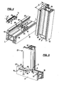
- the post connector consists of two parts, namely a base part 1, of which an embodiment in a perspective oblique view (from above) in Fig. 1 is shown, and a Aufmeneil 2, the perspective in Fig. 2 is shown.
- the base part 1 in turn consists of two parts, namely a base body 3, the -. B. Fig. 4 shows - on a frame strip 5 (from the Fig. 4 only shows a portion) is mounted on the enclosed peripheral surface facing the upper side, while the second portion, namely the attachment part 4, for its attachment to the base body 3 in the arrow in Fig.
- Each spring bar 7 carries at its protruding end in the direction of the respective other spring bar 7 projecting locking projection 9, which when pushed onto the support surface 8 of the associated, to this perpendicular side end surface of the web 6 in the sense of spreading of the two spring tongues 7 is deflected and at the end of the Aufstecknado each in an undercut 10 can detent latching.
- the Aufmeneil 2 will, such as the Fig. 4 . 6, 7 and 8 show well, at the bottom of a post 11 (of which the Fig. 4 to 8 also reproduce only a section), ie, at the end of the frame strip 5 facing surface.
- Such a condition is z. B. from the Fig. 4 to 8 removable.
- the base body 3 itself essentially forms a plate-shaped body, which in its mounting on the frame strip 5 in a mounted on this profile groove between one of the outside of the frame facing outer flange 17 (also referred to as "flashover") on the outer longitudinal side of Frame strip 5 and a groove 18 at the opposite (inner) side edge of the frame strip 5 is arranged.
- the main body 3 extends substantially perpendicular to the longitudinal direction LL of the frame strip 5 and has a substantially rectangular shape in plan view (see. Fig. 1 or 4 ).
- the guide grooves 16 on the upper side of the main body 3 each have a depth t and extend almost over the entire course of the base body 3 in a perpendicular transverse direction to the longitudinal axis L-L of the frame strip 5.
- Fig. 1 shows, in the illustrated embodiment, two holes 19 for countersunk screws between the two guide grooves 16 are mounted, the centers of which is also on a parallel to the two guide grooves 16 extending straight line.
- the support plate 21 extends in the in Fig. 1 illustrated embodiment in the longitudinal direction LL of the frame strip 5, on both sides of the web 6 wing-like manner above, over a total length / ( Fig. 1 ) which corresponds to the width b of the outer flange 22 of the post 11 seated on it in the assembled state ( Fig. 4 ).
- the Anatom 2 consists of a central block portion 23 which forms on its upper, ie the post 11 facing top, the upper planar support surface 13. From her jumps up the mold section 12 for insertion into the hollow cross section 14 of the post 11. In this case, this upper mold portion 12 with respect to the hollow cross-section 14 of the post 11 is formed so that it can be positively inserted into the latter until the lower end surface 15 of the post 11 comes against the upper support surface 13 of the attachment part 2 to the stop.
- the central block part 23 of the Aufmeneiles 2 has a shape and size that substantially corresponds to the shape and size of the lying in the assembled state under him base 3 of the base part 1.
- the central block part 23 is provided on its underside with a lower planar support surface 24, projecting from the two parallel, plate-shaped strips 25 vertically downwards.
- the strips 25 are arranged and their supernatant and their width chosen so that they engage positively in the assembled state of base part 1 and 2 Aufjoneil in the two guide grooves 16 and fill them almost completely in the final assembly state.
- the attachment part 2 can be supplied to the main body 3 such that the strips 25 are inserted from the side of the base body 3 opposite the support plate 21 of the base part (ie from the inside of the frame) into the guide grooves 16 opening there.
- Fig. 2 shows, on its in the assembled state of the support plate 21 opposite side of a flange 26, which extends from the upper support surface 13 downwards and on both sides, perpendicular to the latter, protrudes beyond the support surface 24, and so far that in the mounted state the end surface 27 of the flange portion 26 rests on the top of the two lateral boundary walls of the groove 18 on the frame bar 5.
- the attachment part 2 are further, as z. B. the Fig. 4 .
- the attachment part 2 is displaced relative to the base body 3 so far that the web 6 facing the front end surface 30 of its central block member 23 comes against its facing abutment surface 31 of the web 6 to the plant , which forms a stop against the insertion movement of the Aufpersoneiles 2.
- bores 32 are mounted so that in the collapsed state a through the base body 3 and through the strips 25 in alignment passing through bore 32 is formed.
- This through hole 32 passes both through the base body 3, as well as through the strips 25 therethrough.
- Fig. 4 For mounting a post connector with a base part according to the representation of Fig. 1 first, how Fig. 4 shows, the base body 3 mounted on the top of a frame strip 5 at a corresponding desired location and there fastened by inserted into the holes 19 cap screws (not shown in the figures) on the frame strip 5.
- attachment part 2 is inserted with its upper mold portion 12 to the stop of its upper support surface 13 against the lower end face 15 of the post 11 in the hollow cross section 14 and there in a suitable manner, for. B. by means of screwed through the holes 28 screws, attached to the post 11 (not shown in the figures).
- the post 11 is inserted with the attaching part 2 attached to it from the inside of the later frame forth with its two parallel lower strips 25 in the guide grooves 16 in the base body 3 of the base part 1 and there, with simultaneous support of the support surface 24 of the central block part 23 on the facing surface 20 on the base body 3 of the base part 1, so long in the direction of the web 6 out until the front end surface 30 of the central block member 23 abuts against the facing surface 31 of the web 6.
- the support plate 21 has, as Fig. 1 shows, at their lateral ends to the rear, elastic cover webs 33, which in the assembled state, the associated side edge of the outer flange 22 of the post 11 each comprise laterally positively, as shown in FIGS. 7 and 8 , which both show the final assembly state from different directions, well.
- the support plate 21 of the attachment part 4 has on its underside a substantially smooth surface 34, as this Fig. 3 shows, although a different embodiment than Fig. 1 illustrated for the support plate 21, but the bottom 34 is formed the same in both cases.
- this forms an obliquely outwardly rising surface 35, consisting of a plurality of surface webs, which serves as a support surface for the underside 15 of the outer flange 22 of the post 11.
- the lower surface 34 of the support plate 21 serves to rest on the surface 22 of the outer flange 17 of the frame strip fifth
- the orientation of the surfaces 34 and 35 to each other is such that they, as seen from the outside, diverge by an angle ⁇ (see. Fig. 1 and 4 ). Accordingly, the surface 22 of the outer flange 17 of the frame strip 5 and the lower end surface 15 of the post 11 are arranged diverging outwardly in the same way, so that the support plate 21 is pressed with its inclined surfaces 34 and 35 in the gap S wedge-shaped. In this case, all dimensions are designed so that the support plate 21 in its engaged position (inserted state) completely fills the gap S and thereby subject to a certain pressure between the post 11 and the frame strip 5.
- the support plate 21 is provided on its outwardly facing front and its two lateral statements with a peripheral cover strip 36, which, as Fig. 1 and Fig. 3 show, both on the top slightly above the upper support surface 35 projects upwards, as well as on the bottom slightly beyond the lower corner 34 of the support plate 21 projects down. This supernatant is also from the presentation of Fig. 6 clearly visible.
- the circumferential cover strip 36 results, as Fig. 8 shows a very pleasing, the gap S between the post 11 and frame strip 5 covering and at the same time also sealing effect.
- FIG. 3 Another form of a base part shows Fig. 3 :
- the base part 1 in the form of the support plate 21 differs from the state Fig. 1 in that here not the support plate 21 is latched during assembly on the web 6 and the web 6 is formed integrally with the base body 3. Rather, in the embodiment of the Fig. 3 the support plate 21 is made in one piece with the web 6, while the main body 3 without the web 6 forms an independent part.
- a small protruding molded body 37 is attached to the lower end surface of the web 6. If the web 6 is placed with the support plate 21 from above on the (separate) base body 3, and the molded body 37 is inserted into a corresponding (not shown in the figures) recording on the top of the base body 3 during placement and thereby the form-fitting Aufsteckvorgang out.
- a pair of circular projections 38 is mounted on the lower surface 24 of the Aufjobeiles 2, which rests on the surface 22 of the outer flange 17 of the frame strip 5, which provided during assembly in accordance with the surface 22 of the outer flange 17 of the frame strip 5 Retract receiving openings 39 and thereby determine the exact location of the support plate 21 on the outer flange 17.
- attachment part 4 in the form of a one-piece design of web 6 and support plate 21, however, there is no longer the possibility of the attachment part 4 in a last To mount step, after previously the post 11 has been pushed with the attachment part 2 on the base body 3. Because the attachment part of the support plate 21 and web 6 can then no longer be mounted from the outside through the narrow gap S between post 11 and frame strip 5.
Landscapes
- Engineering & Computer Science (AREA)
- Civil Engineering (AREA)
- Structural Engineering (AREA)
- Mutual Connection Of Rods And Tubes (AREA)
- Orthopedics, Nursing, And Contraception (AREA)
- Connector Housings Or Holding Contact Members (AREA)
Applications Claiming Priority (1)
| Application Number | Priority Date | Filing Date | Title |
|---|---|---|---|
| DE102010007181.1A DE102010007181B4 (de) | 2010-02-08 | 2010-02-08 | Pfostenverbinder |
Publications (2)
| Publication Number | Publication Date |
|---|---|
| EP2354419A2 true EP2354419A2 (fr) | 2011-08-10 |
| EP2354419A3 EP2354419A3 (fr) | 2015-02-18 |
Family
ID=43903895
Family Applications (1)
| Application Number | Title | Priority Date | Filing Date |
|---|---|---|---|
| EP11000031.2A Withdrawn EP2354419A3 (fr) | 2010-02-08 | 2011-01-04 | Connecteur de rembourrage |
Country Status (3)
| Country | Link |
|---|---|
| EP (1) | EP2354419A3 (fr) |
| DE (1) | DE102010007181B4 (fr) |
| RU (1) | RU2011104130A (fr) |
Cited By (7)
| Publication number | Priority date | Publication date | Assignee | Title |
|---|---|---|---|---|
| EP3124734A1 (fr) * | 2015-07-30 | 2017-02-01 | PHI Technik für Fenster und Türen GmbH | Systeme de liaison destine a relier un jambage a un profil de cadre d'une fenetre ou d'une porte en matiere plastique |
| DE102016123889A1 (de) | 2016-12-08 | 2018-06-14 | PHI Technik für Fenster und Türen GmbH | Verbindungsanordnung zum Verbinden eines Pfostens mit einem Rahmenprofil eines Fensters oder einer Türe aus Kunststoff |
| DE102017122328A1 (de) | 2017-09-26 | 2019-03-28 | PHI Technik für Fenster und Türen GmbH | Verfahren und Verbindungsanordnung zum Verbinden eines Pfostens mit einem Rahmenprofil bei einem Fenster oder einer Türe aus Kunststoff |
| DE102018106525A1 (de) | 2018-03-20 | 2019-09-26 | PHI Technik für Fenster und Türen GmbH | Verbindungsanordnung |
| DE202021106237U1 (de) | 2021-11-15 | 2021-11-25 | PHI Technik für Fenster und Türen GmbH | Verbindungsanordnung zum Verbinden eines Pfostens mit einem Rahmenprofil eines Fensters oder einer Türe aus Kunststoff |
| US20220341450A1 (en) * | 2021-04-21 | 2022-10-27 | Rhino Rack Australia Pty Limited | T-joint connector device |
| DE102021129760A1 (de) | 2021-11-15 | 2023-05-17 | PHI Technik für Fenster und Türen GmbH | Verbindungsanordnung zum Verbinden eines Pfostens mit einem Rahmenprofil eines Fensters oder einer Türe aus Kunststoff |
Families Citing this family (2)
| Publication number | Priority date | Publication date | Assignee | Title |
|---|---|---|---|---|
| DE102010025055B4 (de) | 2010-06-25 | 2013-03-21 | PHI Technik für Fenster und Türen GmbH | Pfostenverbinder |
| SE543388C2 (en) * | 2018-06-18 | 2020-12-29 | Munters Europe Ab | A connection device and a box arrangement provided with such connection device |
Citations (1)
| Publication number | Priority date | Publication date | Assignee | Title |
|---|---|---|---|---|
| DE202009003438U1 (de) | 2009-03-11 | 2009-05-28 | PHI Technik für Fenster und Türen GmbH | Pfostenverbinder |
Family Cites Families (3)
| Publication number | Priority date | Publication date | Assignee | Title |
|---|---|---|---|---|
| DE9206625U1 (de) * | 1992-05-15 | 1993-09-16 | Niemann, Hans Dieter, 50169 Kerpen | Verbindung für winklig aneinanderstoßende Hohlprofilstäbe |
| DE9316308U1 (de) * | 1993-10-27 | 1995-02-23 | Niemann, Hans Dieter, 50169 Kerpen | Verbindungsstück für winklig aneinanderstoßende Rahmenstäbe |
| DE19734876A1 (de) * | 1997-08-12 | 1999-02-18 | Peter Willrich | Verbindungselement zur Verbindung eines Hohlteils mit einem auf Stoß anliegenden Profilteil im Tür- oder Fensterbau |
-
2010
- 2010-02-08 DE DE102010007181.1A patent/DE102010007181B4/de active Active
-
2011
- 2011-01-04 EP EP11000031.2A patent/EP2354419A3/fr not_active Withdrawn
- 2011-02-07 RU RU2011104130/03A patent/RU2011104130A/ru not_active Application Discontinuation
Patent Citations (1)
| Publication number | Priority date | Publication date | Assignee | Title |
|---|---|---|---|---|
| DE202009003438U1 (de) | 2009-03-11 | 2009-05-28 | PHI Technik für Fenster und Türen GmbH | Pfostenverbinder |
Cited By (9)
| Publication number | Priority date | Publication date | Assignee | Title |
|---|---|---|---|---|
| EP3124734A1 (fr) * | 2015-07-30 | 2017-02-01 | PHI Technik für Fenster und Türen GmbH | Systeme de liaison destine a relier un jambage a un profil de cadre d'une fenetre ou d'une porte en matiere plastique |
| DE102016123889A1 (de) | 2016-12-08 | 2018-06-14 | PHI Technik für Fenster und Türen GmbH | Verbindungsanordnung zum Verbinden eines Pfostens mit einem Rahmenprofil eines Fensters oder einer Türe aus Kunststoff |
| DE102017122328A1 (de) | 2017-09-26 | 2019-03-28 | PHI Technik für Fenster und Türen GmbH | Verfahren und Verbindungsanordnung zum Verbinden eines Pfostens mit einem Rahmenprofil bei einem Fenster oder einer Türe aus Kunststoff |
| DE102018106525A1 (de) | 2018-03-20 | 2019-09-26 | PHI Technik für Fenster und Türen GmbH | Verbindungsanordnung |
| DE102018106525B4 (de) * | 2018-03-20 | 2025-06-05 | PHI Technik für Fenster und Türen GmbH | Verbindungsanordnung |
| US20220341450A1 (en) * | 2021-04-21 | 2022-10-27 | Rhino Rack Australia Pty Limited | T-joint connector device |
| US12038038B2 (en) * | 2021-04-21 | 2024-07-16 | Rhino Rack Australia Pty Limited | T-joint connector device |
| DE202021106237U1 (de) | 2021-11-15 | 2021-11-25 | PHI Technik für Fenster und Türen GmbH | Verbindungsanordnung zum Verbinden eines Pfostens mit einem Rahmenprofil eines Fensters oder einer Türe aus Kunststoff |
| DE102021129760A1 (de) | 2021-11-15 | 2023-05-17 | PHI Technik für Fenster und Türen GmbH | Verbindungsanordnung zum Verbinden eines Pfostens mit einem Rahmenprofil eines Fensters oder einer Türe aus Kunststoff |
Also Published As
| Publication number | Publication date |
|---|---|
| DE102010007181B4 (de) | 2018-03-01 |
| DE102010007181A1 (de) | 2011-08-11 |
| RU2011104130A (ru) | 2012-08-20 |
| EP2354419A3 (fr) | 2015-02-18 |
Similar Documents
| Publication | Publication Date | Title |
|---|---|---|
| DE102010007181B4 (de) | Pfostenverbinder | |
| DE102009012438B4 (de) | Pfostenverbinder | |
| EP0200760B1 (fr) | Barre profilee pour le serrage des plaques, surtout les plaques en verre, pour des vitrines, distributeurs de vente, mobilier d'exposition et objets semblables | |
| EP1026357B1 (fr) | Profilé d'encadrement pour fenêtres ou portes en bois-métal | |
| DE102015112563A1 (de) | Verbindungsanordnung zum Verbinden eines Pfostens an einem Rahmenprofil eines Fensters oder einer Türe aus Kunststoff | |
| EP0801202B1 (fr) | Raccord de croisement pour croisillons | |
| AT509484B1 (de) | Haltevorrichtung zum verbinden von profilen zu einem flächigen wandelement | |
| DE3200844A1 (de) | Waermedaemmendes verbundprofil | |
| DE102008015989B3 (de) | Schwellenhalter für Türrahmen | |
| DE4313330C2 (de) | Verklammerungsorgan | |
| DE202009003438U1 (de) | Pfostenverbinder | |
| EP1860250A2 (fr) | Profile d'étanchéité | |
| EP2754803B1 (fr) | Crémone de fenêtre ou de porte et tringle pour une telle crémone | |
| EP1643049A2 (fr) | Construction avec profilés porteurs | |
| DE19719013C2 (de) | Mit einem Wandhalter versehenes, im Querschnitt U-förmiges Halteprofil für eine Trennwand | |
| DE102010025055B4 (de) | Pfostenverbinder | |
| DE202012002574U1 (de) | Pfostenverbinder | |
| EP3783184B1 (fr) | Raccord de profil permettant de raccorder des profils de cadre et agencement correspondant | |
| DE2428510C3 (de) | Formwerkzeug zur Herstellung von Kunststoff-Profilteilen | |
| DE2543325A1 (de) | Rahmen zur aufnahme einer fuellungsplatte | |
| EP2017483B1 (fr) | Structure de profilé | |
| DE102007024668A1 (de) | Aufsatzdichtung | |
| EP1388627B1 (fr) | Dispositif de fixation pour une ferrure | |
| DE9107593U1 (de) | Zusammengesetztes Türschild | |
| DE102012005295B3 (de) | Pfostenverbinder |
Legal Events
| Date | Code | Title | Description |
|---|---|---|---|
| PUAI | Public reference made under article 153(3) epc to a published international application that has entered the european phase |
Free format text: ORIGINAL CODE: 0009012 |
|
| AK | Designated contracting states |
Kind code of ref document: A2 Designated state(s): AL AT BE BG CH CY CZ DE DK EE ES FI FR GB GR HR HU IE IS IT LI LT LU LV MC MK MT NL NO PL PT RO RS SE SI SK SM TR |
|
| AX | Request for extension of the european patent |
Extension state: BA ME |
|
| PUAL | Search report despatched |
Free format text: ORIGINAL CODE: 0009013 |
|
| AK | Designated contracting states |
Kind code of ref document: A3 Designated state(s): AL AT BE BG CH CY CZ DE DK EE ES FI FR GB GR HR HU IE IS IT LI LT LU LV MC MK MT NL NO PL PT RO RS SE SI SK SM TR |
|
| AX | Request for extension of the european patent |
Extension state: BA ME |
|
| RIC1 | Information provided on ipc code assigned before grant |
Ipc: E06B 3/964 20060101AFI20150109BHEP Ipc: E06B 3/968 20060101ALN20150109BHEP |
|
| STAA | Information on the status of an ep patent application or granted ep patent |
Free format text: STATUS: THE APPLICATION IS DEEMED TO BE WITHDRAWN |
|
| 18D | Application deemed to be withdrawn |
Effective date: 20150819 |