EP2354643B1 - Agencement de réflecteur - Google Patents
Agencement de réflecteur Download PDFInfo
- Publication number
- EP2354643B1 EP2354643B1 EP11152511.9A EP11152511A EP2354643B1 EP 2354643 B1 EP2354643 B1 EP 2354643B1 EP 11152511 A EP11152511 A EP 11152511A EP 2354643 B1 EP2354643 B1 EP 2354643B1
- Authority
- EP
- European Patent Office
- Prior art keywords
- reflective surfaces
- region
- reflector arrangement
- luminous means
- arrangement according
- Prior art date
- Legal status (The legal status is an assumption and is not a legal conclusion. Google has not performed a legal analysis and makes no representation as to the accuracy of the status listed.)
- Not-in-force
Links
- 239000000463 material Substances 0.000 claims description 19
- 239000004033 plastic Substances 0.000 claims description 15
- 229920003023 plastic Polymers 0.000 claims description 15
- 229910052782 aluminium Inorganic materials 0.000 claims description 11
- XAGFODPZIPBFFR-UHFFFAOYSA-N aluminium Chemical compound [Al] XAGFODPZIPBFFR-UHFFFAOYSA-N 0.000 claims description 11
- 239000004411 aluminium Substances 0.000 claims 1
- 238000004519 manufacturing process Methods 0.000 description 5
- 241000446313 Lamella Species 0.000 description 4
- 238000005286 illumination Methods 0.000 description 3
- 238000001746 injection moulding Methods 0.000 description 3
- 238000007740 vapor deposition Methods 0.000 description 3
- 238000001816 cooling Methods 0.000 description 2
- 238000005516 engineering process Methods 0.000 description 2
- 238000009434 installation Methods 0.000 description 2
- 238000001465 metallisation Methods 0.000 description 2
- 239000011248 coating agent Substances 0.000 description 1
- 238000000576 coating method Methods 0.000 description 1
- 230000001419 dependent effect Effects 0.000 description 1
- 238000010586 diagram Methods 0.000 description 1
- 238000002347 injection Methods 0.000 description 1
- 239000007924 injection Substances 0.000 description 1
- 229910052751 metal Inorganic materials 0.000 description 1
- 239000002184 metal Substances 0.000 description 1
- 239000004417 polycarbonate Substances 0.000 description 1
- 229920000515 polycarbonate Polymers 0.000 description 1
- 238000002310 reflectometry Methods 0.000 description 1
- 229910052709 silver Inorganic materials 0.000 description 1
- 239000004332 silver Substances 0.000 description 1
Images



Classifications
-
- F—MECHANICAL ENGINEERING; LIGHTING; HEATING; WEAPONS; BLASTING
- F21—LIGHTING
- F21V—FUNCTIONAL FEATURES OR DETAILS OF LIGHTING DEVICES OR SYSTEMS THEREOF; STRUCTURAL COMBINATIONS OF LIGHTING DEVICES WITH OTHER ARTICLES, NOT OTHERWISE PROVIDED FOR
- F21V7/00—Reflectors for light sources
- F21V7/0008—Reflectors for light sources providing for indirect lighting
- F21V7/0016—Reflectors for light sources providing for indirect lighting on lighting devices that also provide for direct lighting, e.g. by means of independent light sources, by splitting of the light beam, by switching between both lighting modes
-
- F—MECHANICAL ENGINEERING; LIGHTING; HEATING; WEAPONS; BLASTING
- F21—LIGHTING
- F21V—FUNCTIONAL FEATURES OR DETAILS OF LIGHTING DEVICES OR SYSTEMS THEREOF; STRUCTURAL COMBINATIONS OF LIGHTING DEVICES WITH OTHER ARTICLES, NOT OTHERWISE PROVIDED FOR
- F21V7/00—Reflectors for light sources
- F21V7/0025—Combination of two or more reflectors for a single light source
-
- F—MECHANICAL ENGINEERING; LIGHTING; HEATING; WEAPONS; BLASTING
- F21—LIGHTING
- F21V—FUNCTIONAL FEATURES OR DETAILS OF LIGHTING DEVICES OR SYSTEMS THEREOF; STRUCTURAL COMBINATIONS OF LIGHTING DEVICES WITH OTHER ARTICLES, NOT OTHERWISE PROVIDED FOR
- F21V7/00—Reflectors for light sources
- F21V7/22—Reflectors for light sources characterised by materials, surface treatments or coatings, e.g. dichroic reflectors
- F21V7/24—Reflectors for light sources characterised by materials, surface treatments or coatings, e.g. dichroic reflectors characterised by the material
-
- F—MECHANICAL ENGINEERING; LIGHTING; HEATING; WEAPONS; BLASTING
- F21—LIGHTING
- F21V—FUNCTIONAL FEATURES OR DETAILS OF LIGHTING DEVICES OR SYSTEMS THEREOF; STRUCTURAL COMBINATIONS OF LIGHTING DEVICES WITH OTHER ARTICLES, NOT OTHERWISE PROVIDED FOR
- F21V7/00—Reflectors for light sources
- F21V7/22—Reflectors for light sources characterised by materials, surface treatments or coatings, e.g. dichroic reflectors
- F21V7/28—Reflectors for light sources characterised by materials, surface treatments or coatings, e.g. dichroic reflectors characterised by coatings
-
- F—MECHANICAL ENGINEERING; LIGHTING; HEATING; WEAPONS; BLASTING
- F21—LIGHTING
- F21Y—INDEXING SCHEME ASSOCIATED WITH SUBCLASSES F21K, F21L, F21S and F21V, RELATING TO THE FORM OR THE KIND OF THE LIGHT SOURCES OR OF THE COLOUR OF THE LIGHT EMITTED
- F21Y2103/00—Elongate light sources, e.g. fluorescent tubes
Definitions
- the invention relates to a Retlektoran angel having a first region with first surfaces for reflecting a light emitted from a light source, wherein the first reflective surfaces are provided to be arranged relative to the light source such that they face the light source and with a second region with second reflecting surfaces for further reflection of the light emitted by the light source, wherein the second reflecting surfaces are intended to be arranged relative to the light source such that they are facing away from the light source.
- Such a reflector assembly is as part of a lamp from the DE 101 51958 A1 known.
- the first region is given in this known reflector arrangement by a semicircular in cross-section rear reflector, it being provided that an elongated lamp of the lamp is disposed within the rear reflector.
- the second region is formed by a plurality of pot reflectors arranged in a row, which extend from the back reflector in the intended emission direction of the luminaire.
- the pot reflectors are used for direct lighting of a lying below the light space.
- the rear reflector is used for light output upwards and thus for indirect room lighting.
- the known reflector assembly is formed by a plastic part, which is made by injection molding; the reflective surfaces are formed by vapor deposition of an aluminum coating.
- the luminaire comprises a support element made of metal, to which a fluorescent tube is attached. On the support element close to both sides of light-deflecting elements made of plastic.
- a reflector lamp which comprises a, arranged in a channel-shaped base body fluorescent tube.
- a reflector strip made of aluminum is attached, which has an upper portion, an intermediate portion and a lower portion.
- the upper areas and the intermediate areas are each provided with a white gloss color, while the lower areas are not painted.
- the invention has for its object to provide a corresponding reflector assembly, which is more efficient in terms of lighting technology.
- a reflector arrangement which has a first region with first reflecting surfaces for reflecting a light emitted by a light source, the first reflecting surfaces thereof are provided to be arranged relative to the lighting means such that they face the lighting means. Furthermore, the reflector arrangement has a second region with second reflective surfaces for further reflection of the light emitted by the luminous means, wherein the second reflective surfaces are intended to be arranged relative to the luminous means such that they face away from the luminous means.
- the first region is at least predominantly made of a first material and the second region at least predominantly of a second material, which differs from the first material.
- the second region comprises a plurality of pot reflectors arranged in series. This makes it possible to achieve the impression of a series arrangement of individual light sources with a lamp that is equipped with the reflector assembly.
- the two different materials make it easy to achieve that the first reflecting surfaces have a higher degree of reflection than the second reflecting surfaces. In this way, the efficiency of the reflector arrangement can be increased.
- the first material is aluminum and the second material is plastic.
- the advantages for the second region of the reflector arrangement which can be achieved by the use of plastic can be obtained.
- the first reflective surfaces have a higher reflectance than the second reflective surfaces.
- the reflectance of the first reflective surfaces is more significant to the photorefractive efficiency of the entire reflector array than the reflectance of the second reflective surfaces: the first reflective surfaces, unlike the second reflective surfaces, are arranged to be positioned relative to the illuminant so as to be reflective Light source facing; As a result, light rays emanating from the luminous means are generally reflected several times at the first reflecting surfaces, while they are generally only reflected at most once at the second reflecting surfaces.
- the first region and the second region are disposed directly adjacent to each other.
- the bulb is elongated.
- the illuminant may be a fluorescent tube.
- the second region is a one-piece, made of plastic part.
- the part can be manufactured by injection molding.
- the part is advantageously metallized to form the second reflective surfaces, preferably vapor-deposited with aluminum. This allows a comparatively simple and inexpensive production.
- the second reflective surfaces are intended to be located opposite the first reflective surfaces with respect to the illuminant.
- the first reflective surfaces are intended to be arranged such that they surround the light source on a side facing away from the second reflective surfaces.
- the first region is integrally formed.
- the luminous means is arranged in an inner region of the reflector arrangement, wherein the first reflective surfaces with respect to the second reflective surfaces between a mounting position and a reciprocally movable, so that the illuminant from an outer region of the reflector assembly can be moved to the inner region when the first reflective surfaces are in the mounting position, but not when the first reflective surfaces are in the operating position.
- the first reflective surfaces are provided for generating an indirect illumination and the second reflective surfaces for generating a direct illumination.
- a luminaire which has a luminous means and a reflector arrangement according to the invention, wherein the reflector arrangement is arranged as provided relative to the luminous means.
- the lamp also has guide elements which are designed to guide the first reflective surfaces from the mounting position into the operating position during assembly of the reflector arrangement. This allows for particularly good photometric properties a particularly simple installation.
- Fig. 1 shows a sketch of a cross section of an embodiment of a reflector assembly according to the invention.
- the reflector assembly is suitable for being used as part of a luminaire.
- the reflector arrangement has a first region 2, which comprises first reflective surfaces 12, which are provided for reflection of a light emitted by a light source 6.
- the light-emitting means 6 can in particular represent a light-emitting means 6 of the light (not shown as such in the figures).
- the first reflecting surfaces 12 are intended to be arranged relative to the lighting means 6 such that they face the lighting means 6 are.
- a surface faces the illuminant means that the surface in question has a surface region which is oriented relative to the luminous means in such a way that a light beam emanating from the luminous means, which strikes the surface region directly, is reflected in such a mirror-like manner that, after reflection, it extends in a direction pointing towards the illuminant
- a surface facing away from the luminous means being analogously denoted that the surface in question has no surface area which is relative is arranged oriented to the light source such that a light beam emanating from the light source, which strikes directly on the surface area, is reflected by this surface area such that it extends in a direction pointing to the light source after the reflection.
- the reflector arrangement has a second area 4, which comprises second areas 14 which are provided for further reflection of the light emitted by the illuminating means 6.
- the second reflective surfaces 14 are intended to be arranged such that they are facing away from the luminous means 6.
- the illuminant 6 may be an elongate illuminant 6, the longitudinal axis of the illuminant 6 being perpendicular to the plane of the drawing with reference to the illustration in FIG.
- the illuminant 6 may be a fluorescent tube.
- the second area 4 is in Fig. 3 in a separated form shown in perspective, wherein two juxtaposed second regions are shown.
- the second region 4 may in particular comprise a plurality of pot reflectors arranged in series; In this case, each Topfreflektor example meadow - as outlined in the figures - four of the second reflective surfaces 14 have.
- Fig. 3 are shown only two arranged in series pot reflectors, a first top reflector 21 and a second top reflector 22; however, the second region 4 may comprise more than two in-line pot reflectors.
- the pot reflectors 21, 22 each have a rectangular light exit opening 25. Due to the relative arrangement of Topfreflektoren 21, 22 with each other a lamella 26 is formed between them, so that grid cells of the reflector arrangement are formed by the series of pot reflectors.
- the reflector arrangement according to the Austuhrungsbeispiel shown here can therefore also be referred to as a "grid arrangement”.
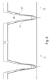
- the lamella 26 is also in the longitudinal sectional view of Fig. 6 outlined.
- a first of the lamella 26 is formed by one of the second reflecting surfaces 14, which represent surfaces of the first pot-type reflector 21.
- the surface concerned is designated by the reference numeral 14 '.
- the first side of the second side of the lamella 26 is accordingly formed by one of the second reflecting surfaces 14, which represent surfaces of the second pot-type reflector 22. In Fig. 6 this area is indicated by the reference numeral 14 ".
- the first region, 2 is at least predominantly made of a first material and the second region, 4 at least predominantly of a second material, which differs from the first material.
- the first material may be aluminum and the second material may be plastic.
- Aluminum has the advantage over plastic in that corresponding reflective surfaces can be achieved which have a higher degree of reflection.
- the so-called "Miro” or “Mira Silver” can be provided as a special aluminum, in this way it is possible to achieve reflectivities of 98%, whereas reflecting surfaces on a plastic part produced by metallization have a lower degree of reflection in the case of polycarbonate, which is vapor-deposited with aluminum, a reflectance of at most about 91% is achieved.
- the first reflecting surfaces 12 preferably have a higher degree of reflection than the second reflecting surfaces 14.
- a high degree of reflection is more significant for the first reflecting surfaces 12 with regard to the lighting efficiency of the entire reflector arrangement than with the second reflecting surfaces 14 in that the first reflecting surfaces 12 face the light-emitting means 6, in general, these surfaces experience multiple reflections of a light beam emanating from the light-emitting means 6, while it is incident on the second light-emitting means reflecting surfaces 14, which are facing away from the light source 6, generally only comes to at most one reflection per light beam.
- the second region 4 is preferably made of plastic, because this allows in particular a simple and inexpensive production.
- the second region 4 is a one-piece, made of plastic part.
- this part may be made by injection molding.
- the second reflective surfaces 14 may be formed by metallization, for example by vapor deposition of aluminum.
- first region 2 and the second region 4 are arranged directly adjacent to one another; It can also be provided that the first reflective surface 12 directly adjoin the second reflective surfaces 14. In this case, it can furthermore be provided, for example, that the arrangement is such that the second reflecting surfaces 14 with respect to the lighting means 6 are arranged at least partially opposite the first reflecting surfaces 12.
- the first reflective surfaces 12 are at least partially provided to be arranged such that they surround the light source 6 on a side facing away from the second reflective surfaces 14 side.
- the reflector arrangement is suitable for emitting the light emitted by the luminous means 6 substantially only via the light exit openings 25.
- a light output can be provided for generating a direct illumination.
- a further light exit opening 29 is formed, for example, the first-mentioned light exit opening 25 is formed opposite and can serve for example to produce an indirect lighting.
- the first region 2 may be formed integrally; in particular two Side retractor areas S1 and S2 may be formed, which are connected to each other via a plurality of connecting elements L , wherein one of the connecting elements L is one of the lamellae 26 on its facing the light source 6 covering arranged.
- a light passage opening is formed between two adjacent connecting elements L , in order to let light from the lighting means 6 to the first-mentioned light exit opening 25.
- the connecting elements L can identify first reflecting surfaces 12, which directly adjoin second reflecting surfaces 14, in particular second reflecting surfaces 14, which represent surfaces of pot reflectors 21, 22.
- the side reflector areas S1, S2 can each have an involute shape in cross-section. This allows a particularly attractive light distribution.
- the slats 26 on its side facing the lamp 6 - with reference to Fig. 6 can therefore be provided in particular that the slats 26 on its side facing the lamp 6 - with reference to Fig. 6
- "open" are designed open and there are covered by a portion of the first area 2, for example, by one of the connecting elements L.
- the corresponding slats are closed at the top by a plastic wall;
- a minimum width of the slats is due, due to the demolding and the cooling side slide in the production as an injection molded part.
- the slats 26 can be made narrower in the reflector assembly according to the invention, so make the distances between two pot reflectors smaller. This has the advantage that a total of more light from the lamp 6 can be delivered through the reflector assembly, so the efficiency of the entire reflector assembly can be increased.
- FIGS. 4 and 5 Two variants are shown, where Fig. 4 a variant with an integrally formed first portion 2 'shows and Fig. 5 a variant with a two-piece trained first area 2 ".
- Fig. 7 shows a partial perspective view of these two variants, wherein the "rear" row of the variant according to Fig. 4 corresponds and the "front" row of the variant according to Fig. 5 ,
- the first reflecting surfaces 12 are reciprocable with respect to the second reflecting surfaces 14 between a mounting position and an operating position.
- the two side reflector areas S1 and S2 are pivoted, as indicated by the arrows, about the pivot axes A1 and A2 , which are parallel to the oblong illuminant (not shown in this figure) 6, ie perpendicular to the drawing plane.
- the light source 6 can be moved from "above” or from outside into the relative arrangement provided for operation in an inner one of the reflector arrangement.
- the first reflecting surfaces 12 of the two side reflector areas S1, S2 can be pivoted about the axes A1 and A2 from the mounting position into the operating position, in which they then surround the lighting means 6 in such a way that they are arranged in the inner region of the reflector assembly is located.
- the two side reflector regions S1, S2 contact one another on the side of the luminous means 6 opposite to the second reflective surfaces 14 in the operating position.
- guide elements are arranged in a lamp having a corresponding reflector arrangement, are guided by the first reflective surfaces 12 of the two side reflector portions S1, S2 from the mounting position to the operating position when the reflector assembly in the remaining light is mounted.
- the first region 2 is formed in two parts or two parts, with a first portion 2.1 and a second portion 2.2
- the first portion 2.1 corresponds to the two side reflector areas S1 , S 2 in the variant according to Fig. 4
- the second portion 2.2 is formed by the connecting elements L.
- first the first portion 2.1 is mounted on the second area 4, then the light source 6 is arranged and finally with the second subsection 2.2.
- the illuminant 6 is surrounded or enclosed in the inner region of the reflector arrangement.
- the luminous means 6 is surrounded almost exclusively by the first reflecting surfaces 12, which due to their particularly high reflectance lead practically to no loss of light.
- the light beams emitted by the luminous means 6 have left the first region 2 and penetrate into the second region 4, they are usually reflected at most once again on the second reflecting surfaces 14 there; the lower reflectance here therefore hardly leads to a significant loss of light.
Landscapes
- Engineering & Computer Science (AREA)
- General Engineering & Computer Science (AREA)
- Non-Portable Lighting Devices Or Systems Thereof (AREA)
- Optical Elements Other Than Lenses (AREA)
Claims (14)
- Ensemble de réflecteurs, comportant- une première zone (2) avec des premières surfaces (12) réfléchissantes pour réfléchir une lumière émise par un moyen d'éclairage (6), lesdites premières surfaces (12) réfléchissantes étant prévues pour être agencées par rapport au moyen d'éclairage (6) de telle sorte qu'elles sont tournées vers ledit moyen d'éclairage (6), et- une deuxième zone (4) avec des deuxièmes surfaces (14) réfléchissantes pour réfléchir également une lumière émise par le moyen d'éclairage (6),
lesdites deuxièmes surfaces (14) réfléchissantes étant prévues pour être agencées par rapport au moyen d'éclairage (6) de telle sorte qu'elles sont détournées du moyen d'éclairage (6),
la première zone (2) étant réalisée en majeure partie dans un premier matériau et la deuxième zone (4) étant réalisée en majeure partie dans un deuxième matériau qui est différent du premier matériau,
caractérisé en ce que
la deuxième zone (4) comporte plusieurs réflecteurs (21, 22) en forme de corps creux disposés en lignes. - Ensemble de réflecteurs selon la revendication 1, dans lequel le premier matériau est de l'aluminium et le deuxième matériau est une matière plastique.
- Ensemble de réflecteurs selon la revendication 1 ou 2, dans lequel les premières surfaces (12) réfléchissantes ont un degré de réflexion plus élevé que celui des deuxièmes surfaces (14) réfléchissantes.
- Ensemble de réflecteurs selon l'une quelconque des revendications précédentes, dans lequel la première zone (2) et la deuxième zone (4) sont disposées de manière directement adjacente l'une à l'autre.
- Ensemble de réflecteurs selon l'une quelconque des revendications précédentes, dans lequel le moyen d'éclairage (6) est allongé, par exemple sous la forme d'un tube fluorescent.
- Ensemble de réflecteurs selon l'une quelconque des revendications précédentes, dans lequel la deuxième zone (4) est une partie d'un seul tenant réalisée en matière plastique.
- Ensemble de réflecteurs selon la revendication 6, dans lequel la partie destinée à former les deuxièmes surfaces (14) réfléchissantes est métallisée, de préférence est métallisée à l'aluminium.
- Ensemble de réflecteurs selon l'une quelconque des revendications précédentes, dans lequel les deuxièmes surfaces (14) réfléchissantes sont prévues pour être agencées par rapport au moyen d'éclairage (6) en face des premières surfaces (12) réfléchissantes.
- Ensemble de réflecteurs selon l'une quelconque des revendications précédentes, dans lequel les premières surfaces (12) réfléchissantes sont prévues pour être agencées de telle sorte qu'elles entourent le moyen d'éclairage (6) sur un côté détourné des deuxièmes surfaces (14) réfléchissantes.
- Ensemble de réflecteurs selon l'une quelconque des revendications précédentes, dans lequel la première zone (2) est réalisée d'un seul tenant.
- Ensemble de réflecteurs selon l'une quelconque des revendications précédentes, dans lequel il est prévu que le moyen d'éclairage (6) est agencé dans une zone intérieure de l'ensemble de réflecteurs, les premières surfaces (12) réfléchissantes pouvant être déplacées en va-et-vient par rapport aux deuxièmes surfaces (14) réfléchissantes, entre une position de montage et une position de service, de telle sorte que le moyen d'éclairage (6) peut être déplacé depuis une zone extérieure de l'ensemble de réflecteurs vers la zone intérieure lorsque les premières surfaces (12) réfléchissantes sont dans la position de montage et non pas lorsque les premières surfaces (12) réfléchissantes sont dans la position de service.
- Ensemble de réflecteurs selon l'une quelconque des revendications précédentes, dans lequel les premières surfaces (12) réfléchissantes sont prévues pour produire un éclairage indirect et les deuxièmes surfaces (14) réfléchissantes sont prévues pour produire un éclairage direct.
- Lampe, comportant- un moyen d'éclairage (6) et- un ensemble de réflecteurs selon l'une quelconque des revendications 1 à 12,ledit ensemble de réflecteurs étant agencé comme prévu par rapport au moyen d'éclairage (6).
- Lampe, comportant- un moyen d'éclairage (6) et- un ensemble de réflecteurs selon la revendication 11, qui est agencé comme prévu par rapport au moyen d'éclairage (6), et- des éléments de guidage, qui sont configurés pour guider les premières surfaces (12) réfléchissantes hors de la position de montage dans la position de service lors d'un montage de l'ensemble de réflecteurs.
Applications Claiming Priority (1)
| Application Number | Priority Date | Filing Date | Title |
|---|---|---|---|
| DE102010001363A DE102010001363A1 (de) | 2010-01-29 | 2010-01-29 | Reflektoranordnung |
Publications (3)
| Publication Number | Publication Date |
|---|---|
| EP2354643A2 EP2354643A2 (fr) | 2011-08-10 |
| EP2354643A3 EP2354643A3 (fr) | 2012-12-05 |
| EP2354643B1 true EP2354643B1 (fr) | 2013-12-04 |
Family
ID=43629574
Family Applications (1)
| Application Number | Title | Priority Date | Filing Date |
|---|---|---|---|
| EP11152511.9A Not-in-force EP2354643B1 (fr) | 2010-01-29 | 2011-01-28 | Agencement de réflecteur |
Country Status (2)
| Country | Link |
|---|---|
| EP (1) | EP2354643B1 (fr) |
| DE (1) | DE102010001363A1 (fr) |
Family Cites Families (8)
| Publication number | Priority date | Publication date | Assignee | Title |
|---|---|---|---|---|
| EP0219255B1 (fr) * | 1985-10-08 | 1993-02-03 | WHITECROFT plc | Luminaires |
| JPS62104302U (fr) * | 1985-12-23 | 1987-07-03 | ||
| DE10151958A1 (de) | 2001-10-22 | 2003-04-30 | Zumtobel Staff Gmbh | Leuchte mit mehreren Topfreflektoren |
| US6783262B2 (en) * | 2003-01-06 | 2004-08-31 | Orfield Laboratories, Inc. | Light fixture, reflector housing, and facility that includes a plurality of light fixtures |
| EP1496308B1 (fr) * | 2003-07-10 | 2011-08-24 | Siteco Beleuchtungstechnik GmbH | Lampe d'éclairage intérieur avec un élément réfractif |
| DE102004017545B4 (de) * | 2004-04-08 | 2014-11-20 | Zumtobel Lighting Gmbh | Reflektor für eine Leuchte, mit einer verstellbaren Reflektorwand und Leuchte mit einem solchen Reflektor |
| TWI285247B (en) * | 2005-02-21 | 2007-08-11 | Seiko Epson Corp | Light source device and projector |
| DE102006047381A1 (de) * | 2006-04-12 | 2007-10-18 | Siteco Beleuchtungstechnik Gmbh | Leuchte mit Kunststoffreflektoren |
-
2010
- 2010-01-29 DE DE102010001363A patent/DE102010001363A1/de not_active Withdrawn
-
2011
- 2011-01-28 EP EP11152511.9A patent/EP2354643B1/fr not_active Not-in-force
Also Published As
| Publication number | Publication date |
|---|---|
| EP2354643A2 (fr) | 2011-08-10 |
| EP2354643A3 (fr) | 2012-12-05 |
| DE102010001363A1 (de) | 2011-08-04 |
Similar Documents
| Publication | Publication Date | Title |
|---|---|---|
| EP1438532B1 (fr) | Appareil d'eclairage dote de plusieurs reflecteurs en forme de coupelle | |
| EP3839334B1 (fr) | Élément optique, ainsi qu'agencement destiné à l'émission de lumière | |
| EP2729838B1 (fr) | Élément optique | |
| EP3015761B1 (fr) | Dispositif d'éclairage avec élément optique | |
| EP1232910A2 (fr) | Feu de véhicule | |
| EP1077344A2 (fr) | Lampe | |
| DE19827264A1 (de) | Fahrzeugleuchte | |
| EP2226551A2 (fr) | Elément optique pour lampes à DEL oblongs | |
| EP1179158A1 (fr) | Dispositif d'eclairage | |
| EP2895790B1 (fr) | Luminaire à paralume équipé de sources lumineuses à led | |
| DE29501661U1 (de) | Leuchte mit mindestens einem Leuchtmittel | |
| DE20004188U1 (de) | Leuchte | |
| DE19957584A1 (de) | Leuchte | |
| DE3215026A1 (de) | Leuchte | |
| DE102012102652B4 (de) | Beleuchtungsanordnung mit Leuchtdioden | |
| EP3631554B1 (fr) | Dispositif optique pour source de lumière | |
| EP2348250B1 (fr) | Lampe à DEL linéaire, notamment lampe annulaire à DEL | |
| EP2354643A2 (fr) | Agencement de réflecteur | |
| DE102023121516A1 (de) | Beleuchtungsvorrichtung | |
| EP1209409B1 (fr) | Dispositif d'éclairage extérieur à caratéristiques d' émission de lumière ameliorées | |
| EP3412963B1 (fr) | Dispositif composant transparent d'un module d'éclairage et module d'éclairage doté d'un tel dispositif composant transparent | |
| EP2257734B1 (fr) | Systeme optique pour lampe à source lumineuse ponctuelle et à caractéristique de rayonnement asymétrique | |
| EP1275899B1 (fr) | Projecteur encastré avec réflecteur latéral | |
| DE19938734A1 (de) | Fahrzeugleuchte | |
| DE102017129505A1 (de) | LED-Band |
Legal Events
| Date | Code | Title | Description |
|---|---|---|---|
| PUAI | Public reference made under article 153(3) epc to a published international application that has entered the european phase |
Free format text: ORIGINAL CODE: 0009012 |
|
| AK | Designated contracting states |
Kind code of ref document: A2 Designated state(s): AL AT BE BG CH CY CZ DE DK EE ES FI FR GB GR HR HU IE IS IT LI LT LU LV MC MK MT NL NO PL PT RO RS SE SI SK SM TR |
|
| AX | Request for extension of the european patent |
Extension state: BA ME |
|
| PUAL | Search report despatched |
Free format text: ORIGINAL CODE: 0009013 |
|
| AK | Designated contracting states |
Kind code of ref document: A3 Designated state(s): AL AT BE BG CH CY CZ DE DK EE ES FI FR GB GR HR HU IE IS IT LI LT LU LV MC MK MT NL NO PL PT RO RS SE SI SK SM TR |
|
| AX | Request for extension of the european patent |
Extension state: BA ME |
|
| RIC1 | Information provided on ipc code assigned before grant |
Ipc: F21V 7/00 20060101AFI20121031BHEP Ipc: F21Y 103/00 20060101ALN20121031BHEP Ipc: F21V 7/22 20060101ALI20121031BHEP Ipc: F21V 11/00 20060101ALI20121031BHEP |
|
| 17P | Request for examination filed |
Effective date: 20130517 |
|
| GRAP | Despatch of communication of intention to grant a patent |
Free format text: ORIGINAL CODE: EPIDOSNIGR1 |
|
| RIC1 | Information provided on ipc code assigned before grant |
Ipc: F21V 7/00 20060101AFI20130619BHEP Ipc: F21V 7/22 20060101ALI20130619BHEP Ipc: F21V 11/00 20060101ALI20130619BHEP Ipc: F21Y 103/00 20060101ALN20130619BHEP |
|
| INTG | Intention to grant announced |
Effective date: 20130717 |
|
| RIN1 | Information on inventor provided before grant (corrected) |
Inventor name: LADSTAETTER, GERALD |
|
| GRAS | Grant fee paid |
Free format text: ORIGINAL CODE: EPIDOSNIGR3 |
|
| GRAA | (expected) grant |
Free format text: ORIGINAL CODE: 0009210 |
|
| AK | Designated contracting states |
Kind code of ref document: B1 Designated state(s): AL AT BE BG CH CY CZ DE DK EE ES FI FR GB GR HR HU IE IS IT LI LT LU LV MC MK MT NL NO PL PT RO RS SE SI SK SM TR |
|
| REG | Reference to a national code |
Ref country code: GB Ref legal event code: FG4D Free format text: NOT ENGLISH |
|
| REG | Reference to a national code |
Ref country code: CH Ref legal event code: EP |
|
| REG | Reference to a national code |
Ref country code: CH Ref legal event code: NV Representative=s name: FIAMMENGHI-FIAMMENGHI, CH |
|
| REG | Reference to a national code |
Ref country code: AT Ref legal event code: REF Ref document number: 643686 Country of ref document: AT Kind code of ref document: T Effective date: 20140115 Ref country code: IE Ref legal event code: FG4D Free format text: LANGUAGE OF EP DOCUMENT: GERMAN |
|
| REG | Reference to a national code |
Ref country code: DE Ref legal event code: R096 Ref document number: 502011001735 Country of ref document: DE Effective date: 20140130 |
|
| REG | Reference to a national code |
Ref country code: NL Ref legal event code: VDEP Effective date: 20131204 |
|
| PG25 | Lapsed in a contracting state [announced via postgrant information from national office to epo] |
Ref country code: FI Free format text: LAPSE BECAUSE OF FAILURE TO SUBMIT A TRANSLATION OF THE DESCRIPTION OR TO PAY THE FEE WITHIN THE PRESCRIBED TIME-LIMIT Effective date: 20131204 Ref country code: LT Free format text: LAPSE BECAUSE OF FAILURE TO SUBMIT A TRANSLATION OF THE DESCRIPTION OR TO PAY THE FEE WITHIN THE PRESCRIBED TIME-LIMIT Effective date: 20131204 Ref country code: SE Free format text: LAPSE BECAUSE OF FAILURE TO SUBMIT A TRANSLATION OF THE DESCRIPTION OR TO PAY THE FEE WITHIN THE PRESCRIBED TIME-LIMIT Effective date: 20131204 Ref country code: NL Free format text: LAPSE BECAUSE OF FAILURE TO SUBMIT A TRANSLATION OF THE DESCRIPTION OR TO PAY THE FEE WITHIN THE PRESCRIBED TIME-LIMIT Effective date: 20131204 Ref country code: HR Free format text: LAPSE BECAUSE OF FAILURE TO SUBMIT A TRANSLATION OF THE DESCRIPTION OR TO PAY THE FEE WITHIN THE PRESCRIBED TIME-LIMIT Effective date: 20131204 Ref country code: NO Free format text: LAPSE BECAUSE OF FAILURE TO SUBMIT A TRANSLATION OF THE DESCRIPTION OR TO PAY THE FEE WITHIN THE PRESCRIBED TIME-LIMIT Effective date: 20140304 |
|
| REG | Reference to a national code |
Ref country code: LT Ref legal event code: MG4D |
|
| PG25 | Lapsed in a contracting state [announced via postgrant information from national office to epo] |
Ref country code: CY Free format text: LAPSE BECAUSE OF FAILURE TO SUBMIT A TRANSLATION OF THE DESCRIPTION OR TO PAY THE FEE WITHIN THE PRESCRIBED TIME-LIMIT Effective date: 20131204 Ref country code: RS Free format text: LAPSE BECAUSE OF FAILURE TO SUBMIT A TRANSLATION OF THE DESCRIPTION OR TO PAY THE FEE WITHIN THE PRESCRIBED TIME-LIMIT Effective date: 20131204 Ref country code: LV Free format text: LAPSE BECAUSE OF FAILURE TO SUBMIT A TRANSLATION OF THE DESCRIPTION OR TO PAY THE FEE WITHIN THE PRESCRIBED TIME-LIMIT Effective date: 20131204 |
|
| BERE | Be: lapsed |
Owner name: ZUMTOBEL LIGHTING GMBH Effective date: 20140131 |
|
| PG25 | Lapsed in a contracting state [announced via postgrant information from national office to epo] |
Ref country code: EE Free format text: LAPSE BECAUSE OF FAILURE TO SUBMIT A TRANSLATION OF THE DESCRIPTION OR TO PAY THE FEE WITHIN THE PRESCRIBED TIME-LIMIT Effective date: 20131204 Ref country code: IS Free format text: LAPSE BECAUSE OF FAILURE TO SUBMIT A TRANSLATION OF THE DESCRIPTION OR TO PAY THE FEE WITHIN THE PRESCRIBED TIME-LIMIT Effective date: 20140404 |
|
| PG25 | Lapsed in a contracting state [announced via postgrant information from national office to epo] |
Ref country code: PL Free format text: LAPSE BECAUSE OF FAILURE TO SUBMIT A TRANSLATION OF THE DESCRIPTION OR TO PAY THE FEE WITHIN THE PRESCRIBED TIME-LIMIT Effective date: 20131204 Ref country code: LU Free format text: LAPSE BECAUSE OF FAILURE TO SUBMIT A TRANSLATION OF THE DESCRIPTION OR TO PAY THE FEE WITHIN THE PRESCRIBED TIME-LIMIT Effective date: 20140128 Ref country code: CZ Free format text: LAPSE BECAUSE OF FAILURE TO SUBMIT A TRANSLATION OF THE DESCRIPTION OR TO PAY THE FEE WITHIN THE PRESCRIBED TIME-LIMIT Effective date: 20131204 Ref country code: ES Free format text: LAPSE BECAUSE OF FAILURE TO SUBMIT A TRANSLATION OF THE DESCRIPTION OR TO PAY THE FEE WITHIN THE PRESCRIBED TIME-LIMIT Effective date: 20131204 Ref country code: RO Free format text: LAPSE BECAUSE OF FAILURE TO SUBMIT A TRANSLATION OF THE DESCRIPTION OR TO PAY THE FEE WITHIN THE PRESCRIBED TIME-LIMIT Effective date: 20131204 Ref country code: SK Free format text: LAPSE BECAUSE OF FAILURE TO SUBMIT A TRANSLATION OF THE DESCRIPTION OR TO PAY THE FEE WITHIN THE PRESCRIBED TIME-LIMIT Effective date: 20131204 Ref country code: PT Free format text: LAPSE BECAUSE OF FAILURE TO SUBMIT A TRANSLATION OF THE DESCRIPTION OR TO PAY THE FEE WITHIN THE PRESCRIBED TIME-LIMIT Effective date: 20140404 |
|
| REG | Reference to a national code |
Ref country code: DE Ref legal event code: R097 Ref document number: 502011001735 Country of ref document: DE |
|
| PG25 | Lapsed in a contracting state [announced via postgrant information from national office to epo] |
Ref country code: MC Free format text: LAPSE BECAUSE OF FAILURE TO SUBMIT A TRANSLATION OF THE DESCRIPTION OR TO PAY THE FEE WITHIN THE PRESCRIBED TIME-LIMIT Effective date: 20131204 |
|
| PLBE | No opposition filed within time limit |
Free format text: ORIGINAL CODE: 0009261 |
|
| STAA | Information on the status of an ep patent application or granted ep patent |
Free format text: STATUS: NO OPPOSITION FILED WITHIN TIME LIMIT |
|
| PG25 | Lapsed in a contracting state [announced via postgrant information from national office to epo] |
Ref country code: DK Free format text: LAPSE BECAUSE OF FAILURE TO SUBMIT A TRANSLATION OF THE DESCRIPTION OR TO PAY THE FEE WITHIN THE PRESCRIBED TIME-LIMIT Effective date: 20131204 |
|
| REG | Reference to a national code |
Ref country code: IE Ref legal event code: MM4A |
|
| 26N | No opposition filed |
Effective date: 20140905 |
|
| REG | Reference to a national code |
Ref country code: DE Ref legal event code: R097 Ref document number: 502011001735 Country of ref document: DE Effective date: 20140905 |
|
| REG | Reference to a national code |
Ref country code: FR Ref legal event code: PLFP Year of fee payment: 5 |
|
| PG25 | Lapsed in a contracting state [announced via postgrant information from national office to epo] |
Ref country code: BE Free format text: LAPSE BECAUSE OF NON-PAYMENT OF DUE FEES Effective date: 20140131 Ref country code: IE Free format text: LAPSE BECAUSE OF NON-PAYMENT OF DUE FEES Effective date: 20140128 |
|
| PG25 | Lapsed in a contracting state [announced via postgrant information from national office to epo] |
Ref country code: SI Free format text: LAPSE BECAUSE OF FAILURE TO SUBMIT A TRANSLATION OF THE DESCRIPTION OR TO PAY THE FEE WITHIN THE PRESCRIBED TIME-LIMIT Effective date: 20131204 |
|
| PGFP | Annual fee paid to national office [announced via postgrant information from national office to epo] |
Ref country code: CH Payment date: 20150124 Year of fee payment: 5 |
|
| PGFP | Annual fee paid to national office [announced via postgrant information from national office to epo] |
Ref country code: FR Payment date: 20150128 Year of fee payment: 5 Ref country code: GB Payment date: 20150202 Year of fee payment: 5 |
|
| PG25 | Lapsed in a contracting state [announced via postgrant information from national office to epo] |
Ref country code: MT Free format text: LAPSE BECAUSE OF FAILURE TO SUBMIT A TRANSLATION OF THE DESCRIPTION OR TO PAY THE FEE WITHIN THE PRESCRIBED TIME-LIMIT Effective date: 20131204 |
|
| PG25 | Lapsed in a contracting state [announced via postgrant information from national office to epo] |
Ref country code: SM Free format text: LAPSE BECAUSE OF FAILURE TO SUBMIT A TRANSLATION OF THE DESCRIPTION OR TO PAY THE FEE WITHIN THE PRESCRIBED TIME-LIMIT Effective date: 20131204 |
|
| PG25 | Lapsed in a contracting state [announced via postgrant information from national office to epo] |
Ref country code: GR Free format text: LAPSE BECAUSE OF FAILURE TO SUBMIT A TRANSLATION OF THE DESCRIPTION OR TO PAY THE FEE WITHIN THE PRESCRIBED TIME-LIMIT Effective date: 20140305 Ref country code: IT Free format text: LAPSE BECAUSE OF FAILURE TO SUBMIT A TRANSLATION OF THE DESCRIPTION OR TO PAY THE FEE WITHIN THE PRESCRIBED TIME-LIMIT Effective date: 20131204 Ref country code: BG Free format text: LAPSE BECAUSE OF FAILURE TO SUBMIT A TRANSLATION OF THE DESCRIPTION OR TO PAY THE FEE WITHIN THE PRESCRIBED TIME-LIMIT Effective date: 20131204 |
|
| PG25 | Lapsed in a contracting state [announced via postgrant information from national office to epo] |
Ref country code: HU Free format text: LAPSE BECAUSE OF FAILURE TO SUBMIT A TRANSLATION OF THE DESCRIPTION OR TO PAY THE FEE WITHIN THE PRESCRIBED TIME-LIMIT; INVALID AB INITIO Effective date: 20110128 Ref country code: TR Free format text: LAPSE BECAUSE OF FAILURE TO SUBMIT A TRANSLATION OF THE DESCRIPTION OR TO PAY THE FEE WITHIN THE PRESCRIBED TIME-LIMIT Effective date: 20131204 |
|
| REG | Reference to a national code |
Ref country code: CH Ref legal event code: PL |
|
| GBPC | Gb: european patent ceased through non-payment of renewal fee |
Effective date: 20160128 |
|
| REG | Reference to a national code |
Ref country code: FR Ref legal event code: ST Effective date: 20160930 |
|
| PG25 | Lapsed in a contracting state [announced via postgrant information from national office to epo] |
Ref country code: GB Free format text: LAPSE BECAUSE OF NON-PAYMENT OF DUE FEES Effective date: 20160128 Ref country code: CH Free format text: LAPSE BECAUSE OF NON-PAYMENT OF DUE FEES Effective date: 20160131 Ref country code: LI Free format text: LAPSE BECAUSE OF NON-PAYMENT OF DUE FEES Effective date: 20160131 |
|
| PG25 | Lapsed in a contracting state [announced via postgrant information from national office to epo] |
Ref country code: FR Free format text: LAPSE BECAUSE OF NON-PAYMENT OF DUE FEES Effective date: 20160201 |
|
| REG | Reference to a national code |
Ref country code: AT Ref legal event code: MM01 Ref document number: 643686 Country of ref document: AT Kind code of ref document: T Effective date: 20160128 |
|
| PG25 | Lapsed in a contracting state [announced via postgrant information from national office to epo] |
Ref country code: AT Free format text: LAPSE BECAUSE OF NON-PAYMENT OF DUE FEES Effective date: 20160128 |
|
| PG25 | Lapsed in a contracting state [announced via postgrant information from national office to epo] |
Ref country code: MK Free format text: LAPSE BECAUSE OF FAILURE TO SUBMIT A TRANSLATION OF THE DESCRIPTION OR TO PAY THE FEE WITHIN THE PRESCRIBED TIME-LIMIT Effective date: 20131204 |
|
| REG | Reference to a national code |
Ref country code: DE Ref legal event code: R084 Ref document number: 502011001735 Country of ref document: DE |
|
| PG25 | Lapsed in a contracting state [announced via postgrant information from national office to epo] |
Ref country code: AL Free format text: LAPSE BECAUSE OF FAILURE TO SUBMIT A TRANSLATION OF THE DESCRIPTION OR TO PAY THE FEE WITHIN THE PRESCRIBED TIME-LIMIT Effective date: 20131204 |
|
| PGFP | Annual fee paid to national office [announced via postgrant information from national office to epo] |
Ref country code: DE Payment date: 20190401 Year of fee payment: 9 |
|
| REG | Reference to a national code |
Ref country code: DE Ref legal event code: R119 Ref document number: 502011001735 Country of ref document: DE |
|
| PG25 | Lapsed in a contracting state [announced via postgrant information from national office to epo] |
Ref country code: DE Free format text: LAPSE BECAUSE OF NON-PAYMENT OF DUE FEES Effective date: 20200801 |