EP2354663B1 - Gasturbinenbrennkammer mit gestufter Verbrennung - Google Patents
Gasturbinenbrennkammer mit gestufter Verbrennung Download PDFInfo
- Publication number
- EP2354663B1 EP2354663B1 EP11152491.4A EP11152491A EP2354663B1 EP 2354663 B1 EP2354663 B1 EP 2354663B1 EP 11152491 A EP11152491 A EP 11152491A EP 2354663 B1 EP2354663 B1 EP 2354663B1
- Authority
- EP
- European Patent Office
- Prior art keywords
- fuel injectors
- fuel
- tertiary
- primary
- liner
- Prior art date
- Legal status (The legal status is an assumption and is not a legal conclusion. Google has not performed a legal analysis and makes no representation as to the accuracy of the status listed.)
- Active
Links
Images



Classifications
-
- F—MECHANICAL ENGINEERING; LIGHTING; HEATING; WEAPONS; BLASTING
- F23—COMBUSTION APPARATUS; COMBUSTION PROCESSES
- F23R—GENERATING COMBUSTION PRODUCTS OF HIGH PRESSURE OR HIGH VELOCITY, e.g. GAS-TURBINE COMBUSTION CHAMBERS
- F23R3/00—Continuous combustion chambers using liquid or gaseous fuel
- F23R3/42—Continuous combustion chambers using liquid or gaseous fuel characterised by the arrangement or form of the flame tubes or combustion chambers
- F23R3/50—Combustion chambers comprising an annular flame tube within an annular casing
-
- F—MECHANICAL ENGINEERING; LIGHTING; HEATING; WEAPONS; BLASTING
- F23—COMBUSTION APPARATUS; COMBUSTION PROCESSES
- F23R—GENERATING COMBUSTION PRODUCTS OF HIGH PRESSURE OR HIGH VELOCITY, e.g. GAS-TURBINE COMBUSTION CHAMBERS
- F23R3/00—Continuous combustion chambers using liquid or gaseous fuel
- F23R3/28—Continuous combustion chambers using liquid or gaseous fuel characterised by the fuel supply
- F23R3/34—Feeding into different combustion zones
- F23R3/346—Feeding into different combustion zones for staged combustion
Definitions
- This invention relates generally to gas turbine engines and, more particularly, to an annular combustor for and a method for operating a gas turbine engine in a staged combustion mode.
- Gas turbine engines such as those used to power modern commercial aircraft or in industrial applications, include a compressor for pressurizing a supply of air, a combustor for burning a hydrocarbon fuel in the presence of the pressurized air, and a turbine for extracting energy from the resultant combustion gases.
- the compressor, combustor and turbine are disposed about a central engine axis with the compressor disposed axially upstream of the combustor and the turbine disposed axially downstream of the combustor.
- An exemplary combustor features an annular combustion chamber defined between a radially inboard liner and a radially outboard liner extending aft from a forward bulkhead.
- the radially outboard liner extends circumferentially about and is radially spaced from the inboard liner, with the combustion chamber extending fore to aft therebetween.
- Exemplary liners are double structured, having an inner heat shield and an outer shell. Arrays of circumferentially distributed combustion air holes penetrate the outboard liner and the inboard liner at one or more axial locations to admit combustion air into the combustion chamber along the length of the combustion chamber.
- a plurality of circumferentially distributed fuel injectors and associated swirlers or air passages is mounted in the forward bulkhead.
- the fuel injectors project into the forward end of the annular combustion chamber to supply the fuel to be combusted.
- the swirlers impart a swirl to inlet air entering the forward end of the combustion chamber at the bulkhead to provide rapid mixing of the fuel and inlet air.
- Commonly assigned U.S. Pat. Nos. 7,093,441 ; 6,606,861 and 6,810,673 disclose exemplary prior art annular combustors for gas turbine engines.
- LIDI combustion strategy recognizes that the conditions for NOx formation are most favorable at elevated combustion flame temperatures, i.e. when the fuel-air ratio is at or near stoichiometric.
- LDI combustion In LDI combustion, more than the stoichiometric amount of air is required to minimize flame temperature whereas the rich-lean combustors drive a rich front end to lean conditions to minimize high stoichiometric flame temperatures.
- the combustion process in a combustor configured for LDI combustion exists in one bulk governing state in which combustion is exclusively stoichiometricly fuel lean. Clearly, local conditions may not be lean given that mixing of the fuel and air require some finite time and spatial volume via mixing to achieve this state. However, overall combustion occurs under fuel lean conditions, that is at an equivalence ratio less than 1.0. The substantial excess of air in the forward combustion zone inhibits NOx formation by suppressing the combustion flame temperature.
- the overall combustion fuel air ratio is determined by the power demand on the engine. At low power demand, the combustor is fired at a relatively low fuel air ratio. At high power demand, the combustor is fired at a relatively high fuel air ratio. Under both low power demand and high power demand operation, the fuel air ratio remains overall fuel lean.
- the capability of operating gas turbine engines having conventional combustors with LDI combustion has proved to be somewhat limited at low fuel air ratios due to reduced combustion efficiency and fuel lean combustion stability concerns.
- EP 1010945 discloses an annular combustor for operating a gas turbine engine in a staged combustion mode according to the preamble of claim 1.
- the invention provides an annular combustor for a gas turbine engine as claimed in claim 1 and a method as claimed in claim 5.
- FIG. 1 there is shown an exemplary embodiment of a turbofan gas turbine engine, designated generally as 100, that includes a turbine having rotating blades that could be repaired when the tips thereof are eroded by use of the method for repairing a turbine blade as disclosed herein.
- the turbofan gas turbine engine 100 includes, from fore-to-aft longitudinally about a central engine axis 105, a fan 102, a low pressure compressor 104, a high pressure compressor 106, a combustor module 120, a high pressure turbine 108, and a low pressure turbine 110.
- a nacelle forms a housing or wrap that surrounds the gas turbine engine 100 to provide an aerodynamic housing about gas turbine engine.
- the nacelle includes, from fore to aft, the engine inlet 132, the fan cowl 134, the engine core cowl 136 and the primary exhaust nozzle 140.
- the annular combustor 120 as disclosed herein is not limited in application to the depicted embodiment of a gas turbine engine, but is applicable to other types of gas turbine engines, including other types of aircraft gas turbine engines, as well as industrial and power generation gas turbine engines.
- the combustor module 120 includes an annular combustor 20 which is disposed about the engine axis 105 in an annular pressure vessel (not shown) defined by a radially inner case (not shown) and a radially outer case (not shown).
- the annular combustor 20 includes a radially inboard liner 32, a radially outboard liner 34 that circumscribes the inboard liner 32, and a forward bulkhead 36.
- the bulkhead 36 extends between the respective forward end of the inboard liner 32 and the forward end of the outboard liner 34.
- the inboard liner 32 and the outboard liner 34 extend longitudinally fore-to-aft from the forward bulkhead 36 to the combustor exit. Collectively, the inboard liner 32, the outboard liner 34 and the forward bulkhead 36 bound the annular combustion chamber 30.
- the forward bulkhead 36 carries a plurality of air swirlers 40, for example typically from 12 to 24 depending upon the size of the engine, disposed in a circumferential array at spaced intervals about the annular combustion chamber 30.
- Each air swirler 40 is disposed at the end of a primary fuel injector 50 which is in flow communication with a fuel supply tube 52 that extends through the outer case (not shown) to convey fuel from an external source to the associated fuel injector 50.
- Each fuel injector 50 includes a spray head through which fuel is sprayed into a stream of air emitted along the centerline of the fuel nozzle.
- the air swirler 40 may have multiple air passages 41, 42 with multiple inlet passages 43.
- pressurized air from the compressor is decelerated as it passes through a diffuser section connecting the outlet of the high pressure compressor 106 and is directed into the annular plenums 90, 92 defined within the annular pressure vessel (not shown), the annular plenum 90 extending circumferentially along and radially inwardly of the inboard liner 32 and the annular plenum 92 extending circumferentially about and radially outwardly of the outboard liner 34.
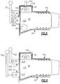
- a portion of this pressured air passes into the combustion chamber through the air inlet passages 43 that impart a spin to the air passing therethrough to provide rapid mixing of this air with the fuel being injected through the associated fuel injector 50 to promote initial combustion of the fuel in a fuel-lean state in a forward portion of the combustion chamber, for example, in the region 115 in FIGs. 2 and 3 .
- the outboard liner 34 includes a forward section 134 that projects generally radially outwardly at the forward end of the outboard liner 34 and extends aftward from the forward bulkhead 36.
- the forward section 134 forms part of the outboard liner 34 and defines a radially outwardly projecting chamber 35 that extends aftward from the bulkhead 36 and circumferentially radially outwardly about and in open relationship to the annular combustion chamber of the annular combustor 20.
- a plurality of secondary fuel injectors 150 are provided for delivering additional fuel to the combustor 20.
- the plurality of secondary fuel injectors are disposed at circumferentially spaced intervals in a ring radially outboard of the plurality of primary fuel injectors 50.
- one secondary fuel injector 150 may be provided in operative association with each primary fuel injector 50.
- the number of secondary fuel injectors 150 may be equal to the number of primary fuel injectors and the secondary fuel injectors 150 are arranged at circumferentially spaced intervals in a ring radially outboard of the ring of primary fuel injectors 50.
- each secondary fuel injector 150 is also arranged in circumferential alignment with an associated primary fuel injector 50.
- Each secondary fuel injector 150 opens at one end through the wall of the forward section 134 into the chamber 35 and at its other end taps into, that is connects in flow communication with, the fuel supply tube 52. As will be explained in further detail hereinafter, in operation of the gas turbine engine, a portion of the fuel flowing through each fuel supply tube 52 passes through the respective secondary fuel injector 150 that taps into that fuel supply tube 52 and is thereby directed into the chamber 35 rather than into the main annular combustion chamber 30.
- One or more igniters 154 are provided for igniting the fuel delivered to the chamber 35.
- the radially outwardly projecting chamber 35 at the forward end of the outboard liner 34 functions both as a combustion stabilization chamber and also as an ignition chamber.
- a radially outwardly projecting combustion chamber 35 is provided in the outboard liner 34 only. There is no corresponding chamber provided in the inboard liner 32.
- a radially inwardly projecting combustion chamber 135 is provided in the inboard liner 32 in addition to the radially outwardly projecting combustion chamber 35. As depicted in FIGs.
- the inboard liner 32 includes a forward section 132 that projects generally radially inwardly at the forward end of the inboard liner 32 and extends aftward from the forward bulkhead 36.
- the forward section 132 forms part of the outboard liner 34 and defines the radially inwardly projecting chamber 135 that extends aftward from the bulkhead 36 and circumferentially radially inwardly about and in open relationship to the annular combustion chamber of the annular combustor 20.
- the chamber 135 no fuel is delivered directly into the chamber 135 and no igniter is operative associated with the chamber 135.
- the radially inwardly projecting chamber 135 does not function as an ignition chamber
- the radially inwardly projecting chamber 1335 like its counterpart radially outwardly projecting chamber 35 in the outboard liner 34, does function as a combustion stabilization chamber.
- the annular combustor 20 includes a plurality of tertiary fuel injectors 250-1, 250-2 opening through the forward bulkhead 36.
- the plurality of tertiary fuel injectors 250-1, 250-2 are disposed at circumferentially spaced intervals and arranged in alternating relationship with the plurality of primary fuel injectors 50.
- the plurality of tertiary fuel injectors may include a first plurality of tertiary fuel injectors 250-1 disposed in a ring located radially outboard of the ring of primary fuel injectors 50 and a second plurality of tertiary fuel injectors 250-2 disposed in a ring located radially inward of the ring of primary fuel injectors 50.
- Each of the first plurality of tertiary fuel injectors 250-1 opens at one end through the forward bulkhead 36 into the annular combustion chamber and at its other end taps into a tertiary fuel supply tube 152.
- Each of the second plurality of tertiary fuel injectors 250-2 opens at one end through the forward bulkhead 36 into the annular combustion chamber and at its other end taps into a tertiary fuel supply tube 156.
- the first and second plurality of tertiary fuel injectors 250-1, 250-2 may be arranged in a plurality of paired sets disposed at circumferentially spaced intervals in radially spaced rings, as illustrated in FIG.
- the annular combustor 20 disclosed herein facilitates operating a gas turbine engine over a range of power demand in accord with the method disclosed herein using staged combustion.
- aircraft gas turbine engines should be capable of operating over a wide power demand range while maintaining combustion efficiency and limiting smoke and NOx emissions.
- power demand on the engine is low during landing and ground taxiing, is intermediate when at cruise, and is high during take-off and climb.
- the amount of fuel delivered to the combustor is directly proportional to the power demand on the engine.
- the overall combustor fuel/air ratio also varies as a function of power demand from a very fuel lean mixture at low power demand to a near stoichiometric fuel air ratio at high power demand.
- delivery of fuel to the combustor 20 is staged over power demand through selectively distributing fuel amongst the primary fuel injectors 50, the secondary fuel injectors 150 and the tertiary fuel injectors 250-1, 250-2.
- the method includes the steps of: injecting a primary fuel supply into a central primary combustion zone of the annular combustion chamber at all load demands, injecting a secondary fuel supply into a secondary combustion zone radially outboard of the central primary combustion zone at all load demands; injecting a first tertiary fuel supply into a first tertiary combustion zone radially outboard of the primary combustion zone and radially inboard of the secondary combustion zone at intermediate to high power demands, and injecting a second tertiary fuel supply into a second tertiary combustion zone radially inboard of the primary combustion zone at high power demands.
- fuel is delivered from fuel supply tube 52 to each of the plurality of primary fuel injectors 50 and each of the plurality of secondary fuel injectors 150, while no fuel is delivered to the combustor 20 through the tertiary fuel injectors 250-1, 250-2.
- the fuel delivered to the primary fuel injectors 50 is injected into a central primary combustion zone 115 extending aftwardly as a ring of flame in the annulus of the annular combustion chamber.
- the fuel delivered to the secondary fuel injectors 150 is injected into a secondary combustion zone 215 within the chamber 35 defined within the radially outwardly projecting portion 134 of the outboard liner 34.
- the secondary combustion zone 215 extends circumferentially around and radially outboard of the forward region of the primary combustion zone 115.
- the fuel injected into the chamber 35 is ignited in the secondary combustion zone 215. Because the secondary combustion zone 215 is confined, radially outwardly and axially, within the chamber 35, a trapped vortex flow dominates within the secondary combustion zone 215. The presence of the trapped vortex flow enhances ignition and combustion stability. Ignition of the fuel delivered to the primary combustion zone 115 may be initiated simply by ignition migration from the secondary combustion zone 215 or may be initiated through additional igniters (not shown) operatively associated directly with the primary fuel injectors 50.
- fuel is also delivered to both sets of the tertiary fuel injectors 250-1, 250-2 through the tertiary fuel supply tube 152.
- the fuel delivered to the first plurality of tertiary fuel injectors 250-1 is injected in a first tertiary combustion zone 315 and the fuel delivered to the second plurality of tertiary fuel injectors is injected into a second tertiary combustion zone 415.
- the first tertiary combustion zone 315 extends circumferentially along the primary combustion zone 115 and lies radially outboard of the primary combustion zone 115 and radially inboard of the combustion zone 215.
- the second tertiary combustion zone 415 also extends circumferentially along the primary combustion zone 115, but lies radially inboard of the primary combustion zone 115.
- fuel is delivered to the primary fuel injectors 50 and to the plurality of secondary fuel injectors 150, but not to either the first plurality of tertiary fuel injectors 250-1 or the second plurality of tertiary fuel injectors 250-2.
- fuel is supplied to as described in the preceding paragraphs to the plurality of primary fuel injectors 50, the plurality of secondary fuel injectors 150, and the first plurality of tertiary fuel injectors 250-1, but fuel is not supplied through the second plurality of tertiary fuel injectors 250-2.
- fuel is supplied to as described in the preceding paragraphs to the plurality of primary fuel injectors 50, the plurality of secondary fuel injectors 150, and both the first plurality of tertiary fuel injectors 250-1 and the second plurality of tertiary fuel injectors 250-2.
- mixing of the combusting fuel and air within the annular combustion chamber is improved by the interaction of the combustion gases at the interfaces of the various zones.
- the air associated with the primary fuel injectors 50 is swirled in a clockwise direction as it enters into the central primary combustion zone 115.
- the interaction of the combustion gases at the interface of the first tertiary combustion zone 315 and the primary combustion zone 115 generates a generally clockwise flow of the combustion gases in the first tertiary zone 315 about the primary combustion zone 115.
- the method includes the steps of combusting the primary fuel supply in the primary combustion zone 115 under fuel lean conditions, that is at an equivalence ratio of less than 1.0 and combusting the secondary fuel supply in the second combustion zone 215 within the stabilization chamber 35 at near stoichiometric conditions, that is at an equivalence ratio of about 1.0.
- the method includes the steps of combusting the primary fuel supply in the primary combustion zone 115 under fuel lean conditions and also combusting the secondary fuel supply in the second combustion zone 215 within the stabilization chamber 35 under fuel lean conditions, that is at an equivalence ratio less than 1.0.
- fuel injected through the tertiary fuel injectors 250-1, 250-2 may be injected as partially premixed fuel and air whereby combustion within the first and second tertiary combustion zones will always occur under fuel lean conditions.
- the secondary combustion zone 215 within the chamber 35 serves as a stabilization zone at low power demand, due to the trapped vortex flow and the near stoichiometric fuel air ratio within the secondary combustion zone, while at high power, fuel lean fuel air ratios are maintained throughout the combustion chamber thereby promoting lower NOx emissions.
- the method includes the steps of combusting the primary fuel supply in a fuel-lean primary combustion zone 115 and combusting the secondary fuel supply in the second combustion zone 215 within the stabilization chamber 35 at an equivalence ratio of about 1.0.
- the method includes the steps of combusting the primary fuel supply in a fuel-lean primary combustion zone 115, combusting the secondary fuel supply in a fuel-lean second combustion zone 215 within the stabilization chamber 35, and combusting the tertiary fuel supply in part in a fuel-lean first tertiary combustion zone 315 and in part in a fuel-lean second tertiary combustion zone 415.
- a secondary combustion zone 215 radially outboard of and circumscribing the forward region of the primary combustion 115 in accord with the method and the annular combustor disclosed herein provides for continuous combustion stabilization over the entire power demand range. Additionally, the establishment at high power demand of a first tertiary combustion zone 315 radially outboard of the primary combustion zone 115 and radially inboard of the secondary combustion zone 215 and of a second tertiary combustion zone 415 radially inboard of the primary combustion zone 115 ensures a more uniform radial exit temperature profile in the combustion gases passing from the annular combustion chamber through the exit guide vanes into the turbine, in comparison to the combustor exit temperature profiles characteristic of conventional annular combustors wherein the fuel is delivered to the annular combustion chamber through a single ring of primary fuel injectors.
- the forward portion 134 of the outboard liner 34 defining the radially outwardly projecting chamber 35 and the forward portion 132 of the inboard liner 32 defining the radially inwardly projecting chamber 135 may be of a double wall construction having an inner wall of ceramic or other material having a high heat resistance and an outer wall of metal or other structural supporting material with the outer wall spaced from the inner wall thereby providing cooling gap therebetween. Cooling air may be passed through the cooling gap to provide for convective cooling of both the inner wall and the outer wall.
- the remaining portion of the outboard liner 34 and, depending upon the embodiment, all or the remaining portion of the inboard liner 32 may be of a double-wall construction and effusion cooled. More specifically, with the exception of the forward sections 132, 134, the inboard liner 32 and the outboard liner 34 may be structured with a support shell and one or more associated heat shields secured to the support shell.
- the heat shields may be formed as a circumferential array of panels, each panel having a longitudinal expanse in the axial direction and a lateral expanse in the circumferential direction and a surface that faces the hot combustion products within the combustion chamber.
- the support shell and heat shields of each of the inboard liner 32 and the outboard liner 34 may be perforated with a plurality of relatively small diameter cooling air holes through which pressurized air passes from the plenums 92, 94 into the annular combustion chamber.
- the cooling holes may be angled downstream whereby the effusion cooling air not only cools the shell and heat shields of each of the inboard liner 32 and the outboard liner 34 as it passes through the heat shield, but also flows along the surface of the heat shield panels facing the combustion chamber thereby providing a protective cooling air layer along that surface.
- the effusion cooling air also gradually mixes into the combustion gases passing through the downstream portion of the combustion chamber thereby assisting in shaping the exit temperature profile of the combustion gases leaving the combustor exit to pass through the exit guide vanes and into the turbine.
- Exemplary liner and heat shield constructions are described and shown in commonly assigned U.S. Patent 7,093,439 .
- Other embodiments, including single-wall liners, are still within the scope of the invention.
Landscapes
- Engineering & Computer Science (AREA)
- Chemical & Material Sciences (AREA)
- Combustion & Propulsion (AREA)
- Mechanical Engineering (AREA)
- General Engineering & Computer Science (AREA)
- Engine Equipment That Uses Special Cycles (AREA)
Claims (7)
- Ringförmige Brennkammer für ein Gasturbinentriebwerk, umfassend:eine innenseitige Auskleidung (32), die sich in Umfangsrichtung erstreckt und sich in Längsrichtung von vorne nach hinten erstreckt;eine außenseitige Auskleidung (34), die sich in Umfangsrichtung erstreckt und sich in Längsrichtung von vorne nach hinten erstreckt und die innenseitige Auskleidung (32) umgrenzt;eine Trennwand (36), die sich zwischen einem vorderen Ende der innenseitigen Auskleidung (32) und einem vorderen Ende der außenseitigen Auskleidung (34) erstreckt und in Zusammenwirkung mit der innenseitigen Auskleidung (32) und der außenseitigen Auskleidung (34) die ringförmige Brennkammer (30) definiert, wobei die außenseitige Auskleidung (34) einen vorderen Abschnitt beinhaltet, der eine radial nach außen vorragende Kammer (35) beinhaltet, die sich von der Trennwand (36) nach hinten erstreckt und in offener Beziehung zu der ringförmigen Brennkammer (30) und der innenseitigen Auskleidung (32) einen vorderen Abschnitt und einen hinteren Abschnitt beinhaltet, wobei der vordere Abschnitt in Richtung der außenseitigen Auskleidung (34) von vorne nach hinten konvergiert;eine Vielzahl von primären Brennstoffeinspritzvorrichtungen (50), die sich zur Zuführung von Brennstoff in die ringförmige Brennkammer (30) durch die Trennwand (36) öffnen, wobei die Vielzahl der primären Brennstoffeinspritzvorrichtungen (50) in in Umfangsrichtung beabstandeten Intervallen in einem Ring radial zwischen der innenseitigen Auskleidung (32) und der außenseitigen Auskleidung (34) angeordnet sind;eine Vielzahl von sekundären Brennstoffeinspritzvorrichtungen (150), die sich durch die Trennwand (36) öffnen und Brennstoff direkt in eine sekundäre Verbrennungszone (215) zuführen, die sich innerhalb der nach außen vorragenden Kammer (35) der außenseitigen Auskleidung (34) befindet, wobei die Vielzahl von sekundären Brennstoffeinspritzvorrichtungen (150) in in Umfangsrichtung beabstandeten Intervallen in einem Ring radial außerhalb der Vielzahl von primären Brennstoffeinspritzvorrichtungen (50) angeordnet sind und in Umfangsrichtung ausgerichtet mit der Vielzahl von primären Brennstoffeinspritzvorrichtungen (50) angeordnet sind;eine erste Vielzahl von tertiären Brennstoffeinspritzvorrichtungen (250-1), die sich durch die Trennwand (36) öffnen und dazu konfiguriert sind, Brennstoff direkt in eine erste tertiäre Verbrennungszone (315) zuzuführen, wobei die erste Vielzahl von tertiären Brennstoffeinspritzvorrichtungen (250-1) in in Umfangsrichtung beabstandeten Intervallen in einem Ring radial außerhalb der Vielzahl von primären Brennstoffeinspritzvorrichtungen (50) und radial innerhalb der Vielzahl von sekundären Brennstoffeinspritzvorrichtungen (150) angeordnet sind; undeine zweite Vielzahl von tertiären Brennstoffeinspritzvorrichtungen (250-2), die in in Umfangsrichtung beabstandeten Intervallen in einem Ring radial innerhalb der Vielzahl von primären Brennstoffeinspritzvorrichtungen (50) angeordnet sind,wobei sich die zweite Vielzahl von tertiären Brennstoffeinspritzvorrichtungen (250-2) durch die Trennwand (36) öffnen und dazu konfiguriert sind, Brennstoff, der der zweiten Vielzahl von tertiären Brennstoffeinspritzvorrichtungen (250-2) zugeführt wird, in eine zweite tertiäre Verbrennungszone (415) einzuspritzen,wobei sich die erste tertiäre Verbrennungszone (315) radial außerhalb einer zentralen primären Verbrennungszone (115) befindet,wobei sich die sekundäre tertiäre Verbrennungszone (415) in Umfangsrichtung entlang der zentralen primären Verbrennungszone (115) erstreckt und radial innerhalb der primären Verbrennungszone (115) liegt,wobei die erste und die zweite Vielzahl von tertiären Brennstoffeinspritzvorrichtungen (250-1, 250-2) in einer Vielzahl von gepaarten Sätzen angeordnet sind, die in in Umfangsrichtung beabstandeten Intervallen angeordnet sind,dadurch gekennzeichnet, dass die erste Vielzahl von tertiären Brennstoffeinspritzvorrichtungen (250-1) und die zweite Vielzahl von tertiären Brennstoffeinspritzvorrichtungen (250-2) in abwechselnder Beziehung mit der Vielzahl von primären Brennstoffeinspritzvorrichtungen (50) angeordnet sind.
- Ringförmige Brennkammer nach Anspruch 1, wobei die erste und die zweite Vielzahl von tertiären Brennstoffeinspritzvorrichtungen (250-1, 250-2) eine Vielzahl von Brennstoffeinspritzvorrichtungen zum Einspritzen eines Vorgemisches aus Brennstoff und Luft umfassen.
- Ringförmige Brennkammer nach Anspruch 1 oder 2, wobei jede der sekundären Brennstoffeinspritzvorrichtungen (150) in Umfangsrichtung mit einer zugehörigen der Vielzahl der primären Brennstoffeinspritzvorrichtungen (50) ausgerichtet angeordnet ist.
- Ringförmige Brennkammer nach Anspruch 3, wobei jede der sekundären Brennstoffeinspritzvorrichtungen (150) in operativer Zuordnung mit einer zugeordneten der Vielzahl der primären Brennstoffeinspritzvorrichtungen (50) bereitgestellt ist.
- Verfahren zum Betreiben eines Gasturbinentriebwerks über einen Leistungsbedarfsbereich, der einen geringen Leistungsbedarf, einen intermediären Leistungsbedarf und einen hohen Leistungsbedarf aufweist, wobei das Gasturbinentriebwerk eine ringförmige Brennkammer nach einem der vorangehenden Ansprüche aufweist, wobei das Verfahren die Folgenden Schritte umfasst:Bereitstellen der nach außen vorragenden Kammer (35) als Stabilisierungskammer (35);Einspritzen einer primären Brennstoffzufuhr in die ringförmige Brennkammer (30) durch die Vielzahl von primären Brennstoffeinspritzvorrichtungen (50);Einspritzen einer sekundären Brennstoffzufuhr in die Stabilisierungskammer (35) durch die Vielzahl von sekundären Brennstoffeinspritzvorrichtungen (150);Einspritzen einer ersten tertiären Brennstoffzufuhr in die ringförmige Brennkammer (30) durch die erste Vielzahl von tertiären Brennstoffeinspritzvorrichtungen (250-1); undEinspritzen einer sekundären tertiären Brennstoffzufuhr in die ringförmige Brennkammer (30) durch die zweite Vielzahl von tertiären Brennstoffeinspritzvorrichtungen (250-2), wobei:während eines geringen Leistungsbedarfs des Gasturbinentriebwerks Brennstoff jeder der Vielzahl von primären Brennstoffeinspritzvorrichtungen (50) und jeder der Vielzahl von sekundären Brennstoffeinspritzvorrichtungen (150) zugeführt wird, aber nicht der ersten Vielzahl von tertiären Brennstoffeinspritzvorrichtungen (250-1) oder der zweiten Vielzahl von tertiären Brennstoffeinspritzvorrichtungen (250-2) ;während eines intermediären oder mittleren Leistungsbedarfs des Gasturbinentriebwerks Brennstoff jeder der Vielzahl von primären Brennstoffeinspritzvorrichtungen (50), jeder der Vielzahl von sekundären Brennstoffeinspritzvorrichtungen (150) und jeder der ersten Vielzahl von tertiären Brennstoffeinspritzvorrichtungen (250-1) zugeführt wird, aber nicht der zweiten Vielzahl von tertiären Brennstoffeinspritzvorrichtungen (250-2); undwährend eines hohen Leistungsbedarfs des Gasturbinentriebwerks Brennstoff jeder der Vielzahl von primären Brennstoffeinspritzvorrichtungen (50), jeder der Vielzahl von sekundären Brennstoffeinspritzvorrichtungen (150), jeder der ersten Vielzahl von tertiären Brennstoffeinspritzvorrichtungen (250-1) und jeder der zweiten Vielzahl von tertiären Brennstoffeinspritzvorrichtungen (250-2) zugeführt wird.
- Verfahren nach Anspruch 5, ferner umfassend die folgenden Schritte während des geringen Leistungsbedarfs:Verbrennen der primären Brennstoffzufuhr in einer brennstoffarmen Zone mit einem Äquivalenzverhältnis von weniger als 1,0; undVerbrennen der sekundären Brennstoffzufuhr in der Stabilisierungskammer (35) mit einem Äquivalenzverhältnis von etwa 1,0.
- Verfahren nach Anspruch 6, ferner umfassend die folgenden Schritte während des hohen Leistungsbedarfs:Verbrennen der primären Brennstoffzufuhr in einer brennstoffarmen Zone mit einem Äquivalenzverhältnis von weniger als 1,0; undVerbrennen der sekundären Brennstoffzufuhr in der Stabilisierungskammer (35) mit einem Äquivalenzverhältnis von weniger als 1,0.
Applications Claiming Priority (1)
| Application Number | Priority Date | Filing Date | Title |
|---|---|---|---|
| US12/696,343 US9068751B2 (en) | 2010-01-29 | 2010-01-29 | Gas turbine combustor with staged combustion |
Publications (4)
| Publication Number | Publication Date |
|---|---|
| EP2354663A2 EP2354663A2 (de) | 2011-08-10 |
| EP2354663A3 EP2354663A3 (de) | 2015-03-11 |
| EP2354663B1 true EP2354663B1 (de) | 2021-03-03 |
| EP2354663B8 EP2354663B8 (de) | 2021-04-21 |
Family
ID=43902764
Family Applications (1)
| Application Number | Title | Priority Date | Filing Date |
|---|---|---|---|
| EP11152491.4A Active EP2354663B8 (de) | 2010-01-29 | 2011-01-28 | Gasturbinenbrennkammer mit gestufter Verbrennung |
Country Status (2)
| Country | Link |
|---|---|
| US (1) | US9068751B2 (de) |
| EP (1) | EP2354663B8 (de) |
Families Citing this family (43)
| Publication number | Priority date | Publication date | Assignee | Title |
|---|---|---|---|---|
| US8464538B2 (en) * | 2010-12-17 | 2013-06-18 | General Electric Company | Trapped vortex combustor and method of operating thereof |
| US8950189B2 (en) * | 2011-06-28 | 2015-02-10 | United Technologies Corporation | Gas turbine engine staged fuel injection using adjacent bluff body and swirler fuel injectors |
| GB2492762B (en) | 2011-07-11 | 2015-12-23 | Rolls Royce Plc | A Method of Mixing Fuel and Air in a Combustion Chamber |
| US9416972B2 (en) | 2011-12-07 | 2016-08-16 | Pratt & Whitney Canada Corp. | Two-stage combustor for gas turbine engine |
| US9194586B2 (en) | 2011-12-07 | 2015-11-24 | Pratt & Whitney Canada Corp. | Two-stage combustor for gas turbine engine |
| US9243802B2 (en) | 2011-12-07 | 2016-01-26 | Pratt & Whitney Canada Corp. | Two-stage combustor for gas turbine engine |
| US9134028B2 (en) | 2012-01-18 | 2015-09-15 | Pratt & Whitney Canada Corp. | Combustor for gas turbine engine |
| US9074773B2 (en) * | 2012-02-07 | 2015-07-07 | General Electric Company | Combustor assembly with trapped vortex cavity |
| CN103277814B (zh) * | 2013-05-10 | 2015-06-17 | 南京航空航天大学 | 富油燃烧/快速淬熄/贫油燃烧与贫油预混预蒸发组合低排放驻涡燃烧室 |
| CN103277811B (zh) * | 2013-05-10 | 2015-10-28 | 南京航空航天大学 | 单凹腔驻涡燃烧室 |
| WO2015069358A2 (en) * | 2013-09-11 | 2015-05-14 | United Technologies Corporation | Ceramic liner for a turbine exhaust case |
| EP3071816B1 (de) | 2013-11-21 | 2019-09-18 | United Technologies Corporation | Kühlung einer mehrwandigen struktur eines turbinenmotors |
| WO2015122950A2 (en) | 2013-11-21 | 2015-08-20 | United Technologies Corporation | Turbine engine multi-walled structure with internal cooling element(s) |
| EP3071887B1 (de) | 2013-11-22 | 2020-03-11 | United Technologies Corporation | Mehrwandige struktur eines turbinenmotors mit kühlelementen |
| EP3967854B1 (de) | 2013-11-25 | 2023-07-05 | Raytheon Technologies Corporation | Anordnung für ein turbinentriebwerk |
| US10502422B2 (en) | 2013-12-05 | 2019-12-10 | United Technologies Corporation | Cooling a quench aperture body of a combustor wall |
| EP3077726B1 (de) | 2013-12-06 | 2021-03-03 | United Technologies Corporation | Kühlung eines brennkammerhitzeschilds in der nähe einer löschöffnung |
| EP3077727B1 (de) | 2013-12-06 | 2019-10-09 | United Technologies Corporation | Eine baugruppe für einen turbinenmotor |
| US10378768B2 (en) | 2013-12-06 | 2019-08-13 | United Technologies Corporation | Combustor quench aperture cooling |
| US10968829B2 (en) | 2013-12-06 | 2021-04-06 | Raytheon Technologies Corporation | Cooling an igniter body of a combustor wall |
| WO2015117137A1 (en) | 2014-02-03 | 2015-08-06 | United Technologies Corporation | Film cooling a combustor wall of a turbine engine |
| CN104033927B (zh) * | 2014-06-12 | 2016-02-03 | 中国航空动力机械研究所 | 基于rql原理的燃烧室及带有该燃烧室的航空发动机 |
| US9915480B2 (en) | 2014-07-03 | 2018-03-13 | United Technologies Corporation | Tube assembly |
| US9976743B2 (en) | 2014-07-03 | 2018-05-22 | United Technologies Corporation | Dilution hole assembly |
| US9759356B2 (en) | 2014-07-03 | 2017-09-12 | United Technologies Corporation | Insulated flowpath assembly |
| US10208673B2 (en) | 2014-07-03 | 2019-02-19 | United Technologies Corporation | Fuel dispensing apparatus and method of operation |
| FR3039254B1 (fr) | 2015-07-24 | 2021-10-08 | Snecma | Chambre de combustion comportant des dispositifs d'injection additionnels debouchant directement dans les zones de recirculation de coin, turbomachine la comprenant, et procede d'alimentation en carburant de celle-ci |
| WO2018190926A1 (en) * | 2017-04-13 | 2018-10-18 | General Electric Company | Single cavity trapped vortex combustor |
| US11262073B2 (en) | 2017-05-02 | 2022-03-01 | General Electric Company | Trapped vortex combustor for a gas turbine engine with a driver airflow channel |
| US20190017441A1 (en) * | 2017-07-17 | 2019-01-17 | General Electric Company | Gas turbine engine combustor |
| CN107543201B (zh) * | 2017-07-25 | 2019-08-09 | 西北工业大学 | 一种贫油直接喷射及混合低污染燃烧室 |
| EP3450850A1 (de) * | 2017-09-05 | 2019-03-06 | Siemens Aktiengesellschaft | Gasturbinenbrennkammeranordnung mit hohlraum zum erzeugen eingeschlossener wirbel |
| US10823422B2 (en) * | 2017-10-17 | 2020-11-03 | General Electric Company | Tangential bulk swirl air in a trapped vortex combustor for a gas turbine engine |
| US20190186438A1 (en) * | 2017-12-20 | 2019-06-20 | Plasma Igniter, LLC | Electromagnetic Wave Modification of Fuel in a Power-generation Turbine |
| US11384940B2 (en) | 2019-01-23 | 2022-07-12 | General Electric Company | Gas turbine load/unload path control |
| US11174792B2 (en) | 2019-05-21 | 2021-11-16 | General Electric Company | System and method for high frequency acoustic dampers with baffles |
| US11156164B2 (en) | 2019-05-21 | 2021-10-26 | General Electric Company | System and method for high frequency accoustic dampers with caps |
| US11566790B1 (en) | 2021-10-28 | 2023-01-31 | General Electric Company | Methods of operating a turbomachine combustor on hydrogen |
| CN115076722B (zh) * | 2022-06-01 | 2023-06-06 | 南京航空航天大学 | 一种燃油预蒸发式凹腔驻涡火焰稳定器及其工作方法 |
| US12130016B1 (en) | 2023-05-31 | 2024-10-29 | General Electric Company | Turbine engine including a combustor |
| US20240401807A1 (en) * | 2023-05-31 | 2024-12-05 | General Electric Company | Turbine engine including a combustor |
| US12535215B2 (en) * | 2023-08-22 | 2026-01-27 | General Electric Company | Combustor including a steam injector operably injecting steam into a trapped vortex cavity |
| US12416409B2 (en) | 2024-02-08 | 2025-09-16 | General Electric Company | Gas turbine engine having a combustion section with steam provided to second combustor plenum |
Citations (4)
| Publication number | Priority date | Publication date | Assignee | Title |
|---|---|---|---|---|
| US4343147A (en) * | 1980-03-07 | 1982-08-10 | Solar Turbines Incorporated | Combustors and combustion systems |
| US5469700A (en) * | 1991-10-29 | 1995-11-28 | Rolls-Royce Plc | Turbine engine control system |
| US6370863B2 (en) * | 1998-07-27 | 2002-04-16 | Asea Brown Boveri Ag | Method of operating a gas-turbine chamber with gaseous fuel |
| US20020189260A1 (en) * | 2001-06-19 | 2002-12-19 | Snecma Moteurs | Gas turbine combustion chambers |
Family Cites Families (50)
| Publication number | Priority date | Publication date | Assignee | Title |
|---|---|---|---|---|
| US4030875A (en) | 1975-12-22 | 1977-06-21 | General Electric Company | Integrated ceramic-metal combustor |
| FR2340453A1 (fr) | 1976-02-06 | 1977-09-02 | Snecma | Corps de chambre de combustion, notamment pour turboreacteurs |
| US4292801A (en) * | 1979-07-11 | 1981-10-06 | General Electric Company | Dual stage-dual mode low nox combustor |
| US5435139A (en) | 1991-03-22 | 1995-07-25 | Rolls-Royce Plc | Removable combustor liner for gas turbine engine combustor |
| US5220795A (en) | 1991-04-16 | 1993-06-22 | General Electric Company | Method and apparatus for injecting dilution air |
| US5239818A (en) * | 1992-03-30 | 1993-08-31 | General Electric Company | Dilution pole combustor and method |
| GB2278431A (en) | 1993-05-24 | 1994-11-30 | Rolls Royce Plc | A gas turbine engine combustion chamber |
| US5402634A (en) * | 1993-10-22 | 1995-04-04 | United Technologies Corporation | Fuel supply system for a staged combustor |
| GB2284884B (en) | 1993-12-16 | 1997-12-10 | Rolls Royce Plc | A gas turbine engine combustion chamber |
| GB9410233D0 (en) | 1994-05-21 | 1994-07-06 | Rolls Royce Plc | A gas turbine engine combustion chamber |
| US6182451B1 (en) | 1994-09-14 | 2001-02-06 | Alliedsignal Inc. | Gas turbine combustor waving ceramic combustor cans and an annular metallic combustor |
| DE4446945B4 (de) * | 1994-12-28 | 2005-03-17 | Alstom | Gasbetriebener Vormischbrenner |
| US5758503A (en) | 1995-05-03 | 1998-06-02 | United Technologies Corporation | Gas turbine combustor |
| US5791148A (en) * | 1995-06-07 | 1998-08-11 | General Electric Company | Liner of a gas turbine engine combustor having trapped vortex cavity |
| US6378286B2 (en) | 1995-06-16 | 2002-04-30 | Power Tech Associates, Inc. | Low NOX gas turbine combustor liner |
| US5782294A (en) | 1995-12-18 | 1998-07-21 | United Technologies Corporation | Cooled liner apparatus |
| FR2748088B1 (fr) | 1996-04-24 | 1998-05-29 | Snecma | Optimisation du melange de gaz brules dans une chambre de combustion annulaire |
| US5983642A (en) | 1997-10-13 | 1999-11-16 | Siemens Westinghouse Power Corporation | Combustor with two stage primary fuel tube with concentric members and flow regulating |
| FR2770283B1 (fr) * | 1997-10-29 | 1999-11-19 | Snecma | Chambre de combustion pour turbomachine |
| US6240731B1 (en) | 1997-12-31 | 2001-06-05 | United Technologies Corporation | Low NOx combustor for gas turbine engine |
| US6047539A (en) | 1998-04-30 | 2000-04-11 | General Electric Company | Method of protecting gas turbine combustor components against water erosion and hot corrosion |
| US6295801B1 (en) * | 1998-12-18 | 2001-10-02 | General Electric Company | Fuel injector bar for gas turbine engine combustor having trapped vortex cavity |
| GB2361303B (en) | 2000-04-14 | 2004-10-20 | Rolls Royce Plc | Wall structure for a gas turbine engine combustor |
| US6481209B1 (en) * | 2000-06-28 | 2002-11-19 | General Electric Company | Methods and apparatus for decreasing combustor emissions with swirl stabilized mixer |
| US6334298B1 (en) * | 2000-07-14 | 2002-01-01 | General Electric Company | Gas turbine combustor having dome-to-liner joint |
| GB0019533D0 (en) * | 2000-08-10 | 2000-09-27 | Rolls Royce Plc | A combustion chamber |
| US6606861B2 (en) | 2001-02-26 | 2003-08-19 | United Technologies Corporation | Low emissions combustor for a gas turbine engine |
| FR2829228B1 (fr) * | 2001-08-28 | 2005-07-15 | Snecma Moteurs | Chambre de combustion annulaire a double tete etagee |
| JP2003113721A (ja) | 2001-10-03 | 2003-04-18 | Mitsubishi Heavy Ind Ltd | ガスタービン燃焼器における燃料比率調節方法及び装置 |
| US6701714B2 (en) | 2001-12-05 | 2004-03-09 | United Technologies Corporation | Gas turbine combustor |
| DE10160997A1 (de) * | 2001-12-12 | 2003-07-03 | Rolls Royce Deutschland | Magervormischbrenner für eine Gasturbine sowie Verfahren zum Betrieb eines Magervormischbrenners |
| JP4134311B2 (ja) | 2002-03-08 | 2008-08-20 | 独立行政法人 宇宙航空研究開発機構 | ガスタービン燃焼器 |
| US6571566B1 (en) | 2002-04-02 | 2003-06-03 | Lennox Manufacturing Inc. | Method of determining refrigerant charge level in a space temperature conditioning system |
| US7093439B2 (en) | 2002-05-16 | 2006-08-22 | United Technologies Corporation | Heat shield panels for use in a combustor for a gas turbine engine |
| JP3978086B2 (ja) * | 2002-05-31 | 2007-09-19 | 三菱重工業株式会社 | 航空機用ガスタービンシステム,及びガスタービンシステム並びにその動作方法 |
| US6735949B1 (en) * | 2002-06-11 | 2004-05-18 | General Electric Company | Gas turbine engine combustor can with trapped vortex cavity |
| US6772595B2 (en) | 2002-06-25 | 2004-08-10 | Power Systems Mfg., Llc | Advanced cooling configuration for a low emissions combustor venturi |
| EP1400751A1 (de) | 2002-09-17 | 2004-03-24 | Siemens Aktiengesellschaft | Brennkammer für eine Gasturbine |
| US6962055B2 (en) * | 2002-09-27 | 2005-11-08 | United Technologies Corporation | Multi-point staging strategy for low emission and stable combustion |
| JP3975232B2 (ja) * | 2002-10-22 | 2007-09-12 | 川崎重工業株式会社 | ガスタービンエンジンの制御方法および制御システム |
| US6968699B2 (en) * | 2003-05-08 | 2005-11-29 | General Electric Company | Sector staging combustor |
| US20040226299A1 (en) | 2003-05-12 | 2004-11-18 | Drnevich Raymond Francis | Method of reducing NOX emissions of a gas turbine |
| US6923001B2 (en) * | 2003-07-14 | 2005-08-02 | Siemens Westinghouse Power Corporation | Pilotless catalytic combustor |
| US7146815B2 (en) | 2003-07-31 | 2006-12-12 | United Technologies Corporation | Combustor |
| US7093441B2 (en) * | 2003-10-09 | 2006-08-22 | United Technologies Corporation | Gas turbine annular combustor having a first converging volume and a second converging volume, converging less gradually than the first converging volume |
| US7363763B2 (en) | 2003-10-23 | 2008-04-29 | United Technologies Corporation | Combustor |
| US6935117B2 (en) | 2003-10-23 | 2005-08-30 | United Technologies Corporation | Turbine engine fuel injector |
| US7506511B2 (en) * | 2003-12-23 | 2009-03-24 | Honeywell International Inc. | Reduced exhaust emissions gas turbine engine combustor |
| DE102004015187A1 (de) * | 2004-03-29 | 2005-10-20 | Alstom Technology Ltd Baden | Brennkammer für eine Gasturbine und zugehöriges Betriebsverfahren |
| US7926284B2 (en) | 2006-11-30 | 2011-04-19 | Honeywell International Inc. | Quench jet arrangement for annular rich-quench-lean gas turbine combustors |
-
2010
- 2010-01-29 US US12/696,343 patent/US9068751B2/en active Active
-
2011
- 2011-01-28 EP EP11152491.4A patent/EP2354663B8/de active Active
Patent Citations (4)
| Publication number | Priority date | Publication date | Assignee | Title |
|---|---|---|---|---|
| US4343147A (en) * | 1980-03-07 | 1982-08-10 | Solar Turbines Incorporated | Combustors and combustion systems |
| US5469700A (en) * | 1991-10-29 | 1995-11-28 | Rolls-Royce Plc | Turbine engine control system |
| US6370863B2 (en) * | 1998-07-27 | 2002-04-16 | Asea Brown Boveri Ag | Method of operating a gas-turbine chamber with gaseous fuel |
| US20020189260A1 (en) * | 2001-06-19 | 2002-12-19 | Snecma Moteurs | Gas turbine combustion chambers |
Also Published As
| Publication number | Publication date |
|---|---|
| US9068751B2 (en) | 2015-06-30 |
| US20110185735A1 (en) | 2011-08-04 |
| EP2354663A3 (de) | 2015-03-11 |
| EP2354663B8 (de) | 2021-04-21 |
| EP2354663A2 (de) | 2011-08-10 |
Similar Documents
| Publication | Publication Date | Title |
|---|---|---|
| US9068751B2 (en) | Gas turbine combustor with staged combustion | |
| EP2357412B1 (de) | Gasturbinenbrennkammer mit variablem Luftstrom | |
| EP2479498B1 (de) | Gasturbinenbrennkammer und Betriebsverfahren | |
| EP2503245B1 (de) | Gasturbinenbrennkammer | |
| EP2479497B1 (de) | Gasturbinenbrennkammer | |
| EP1795809B1 (de) | Gasturbinenbrennkammer | |
| US7762073B2 (en) | Pilot mixer for mixer assembly of a gas turbine engine combustor having a primary fuel injector and a plurality of secondary fuel injection ports | |
| EP2481982B2 (de) | Mischeranordnung für einen Gasturbinenmotor | |
| EP2481987B1 (de) | Mischeranordnung für einen Gasturbinenmotor | |
| US7878000B2 (en) | Pilot fuel injector for mixer assembly of a high pressure gas turbine engine | |
| US10465909B2 (en) | Mini mixing fuel nozzle assembly with mixing sleeve | |
| US9416970B2 (en) | Combustor heat panel arrangement having holes offset from seams of a radially opposing heat panel | |
| EP2236930A2 (de) | Brenner für Gasturbinentriebwerk | |
| US10288291B2 (en) | Air-shielded fuel injection assembly to facilitate reduced NOx emissions in a combustor system | |
| GB2492762A (en) | Combustion Chamber With Improved Air/Fuel Mixing | |
| GB2451517A (en) | Pilot mixer for mixer assembly of a gas turbine engine combustor having a primary fuel injector and a plurality of secondary fuel injection ports | |
| CA2597846A1 (en) | Pilot fuel injector for mixer assembly of a high pressure gas turbine engine | |
| CA2596789C (en) | Pilot mixer for mixer assembly of a gas turbine engine combustor having a primary fuel injector and a plurality of secondary fuel injection ports |
Legal Events
| Date | Code | Title | Description |
|---|---|---|---|
| PUAI | Public reference made under article 153(3) epc to a published international application that has entered the european phase |
Free format text: ORIGINAL CODE: 0009012 |
|
| AK | Designated contracting states |
Kind code of ref document: A2 Designated state(s): AL AT BE BG CH CY CZ DE DK EE ES FI FR GB GR HR HU IE IS IT LI LT LU LV MC MK MT NL NO PL PT RO RS SE SI SK SM TR |
|
| AX | Request for extension of the european patent |
Extension state: BA ME |
|
| PUAL | Search report despatched |
Free format text: ORIGINAL CODE: 0009013 |
|
| AK | Designated contracting states |
Kind code of ref document: A3 Designated state(s): AL AT BE BG CH CY CZ DE DK EE ES FI FR GB GR HR HU IE IS IT LI LT LU LV MC MK MT NL NO PL PT RO RS SE SI SK SM TR |
|
| AX | Request for extension of the european patent |
Extension state: BA ME |
|
| RIC1 | Information provided on ipc code assigned before grant |
Ipc: F23R 3/50 20060101AFI20150205BHEP Ipc: F23R 3/34 20060101ALI20150205BHEP |
|
| 17P | Request for examination filed |
Effective date: 20150907 |
|
| RBV | Designated contracting states (corrected) |
Designated state(s): AL AT BE BG CH CY CZ DE DK EE ES FI FR GB GR HR HU IE IS IT LI LT LU LV MC MK MT NL NO PL PT RO RS SE SI SK SM TR |
|
| RAP1 | Party data changed (applicant data changed or rights of an application transferred) |
Owner name: UNITED TECHNOLOGIES CORPORATION |
|
| STAA | Information on the status of an ep patent application or granted ep patent |
Free format text: STATUS: EXAMINATION IS IN PROGRESS |
|
| 17Q | First examination report despatched |
Effective date: 20180316 |
|
| GRAP | Despatch of communication of intention to grant a patent |
Free format text: ORIGINAL CODE: EPIDOSNIGR1 |
|
| STAA | Information on the status of an ep patent application or granted ep patent |
Free format text: STATUS: GRANT OF PATENT IS INTENDED |
|
| INTG | Intention to grant announced |
Effective date: 20181126 |
|
| GRAJ | Information related to disapproval of communication of intention to grant by the applicant or resumption of examination proceedings by the epo deleted |
Free format text: ORIGINAL CODE: EPIDOSDIGR1 |
|
| STAA | Information on the status of an ep patent application or granted ep patent |
Free format text: STATUS: EXAMINATION IS IN PROGRESS |
|
| INTC | Intention to grant announced (deleted) | ||
| GRAP | Despatch of communication of intention to grant a patent |
Free format text: ORIGINAL CODE: EPIDOSNIGR1 |
|
| STAA | Information on the status of an ep patent application or granted ep patent |
Free format text: STATUS: GRANT OF PATENT IS INTENDED |
|
| INTG | Intention to grant announced |
Effective date: 20200918 |
|
| GRAS | Grant fee paid |
Free format text: ORIGINAL CODE: EPIDOSNIGR3 |
|
| GRAA | (expected) grant |
Free format text: ORIGINAL CODE: 0009210 |
|
| STAA | Information on the status of an ep patent application or granted ep patent |
Free format text: STATUS: THE PATENT HAS BEEN GRANTED |
|
| AK | Designated contracting states |
Kind code of ref document: B1 Designated state(s): AL AT BE BG CH CY CZ DE DK EE ES FI FR GB GR HR HU IE IS IT LI LT LU LV MC MK MT NL NO PL PT RO RS SE SI SK SM TR |
|
| GRAT | Correction requested after decision to grant or after decision to maintain patent in amended form |
Free format text: ORIGINAL CODE: EPIDOSNCDEC |
|
| REG | Reference to a national code |
Ref country code: GB Ref legal event code: FG4D |
|
| REG | Reference to a national code |
Ref country code: DE Ref legal event code: R081 Ref document number: 602011070279 Country of ref document: DE Owner name: RAYTHEON TECHNOLOGIES CORPORATION, FARMINGTON, US Free format text: FORMER OWNER: UNITED TECHNOLOGIES CORP., FARMINGTON, CONN., US Ref country code: DE Ref legal event code: R081 Ref document number: 602011070279 Country of ref document: DE Owner name: RTX CORPORATION (N.D.GES.D. STAATES DELAWARE),, US Free format text: FORMER OWNER: UNITED TECHNOLOGIES CORP., FARMINGTON, CONN., US |
|
| REG | Reference to a national code |
Ref country code: AT Ref legal event code: REF Ref document number: 1367625 Country of ref document: AT Kind code of ref document: T Effective date: 20210315 Ref country code: CH Ref legal event code: EP |
|
| REG | Reference to a national code |
Ref country code: DE Ref legal event code: R096 Ref document number: 602011070279 Country of ref document: DE |
|
| RAP2 | Party data changed (patent owner data changed or rights of a patent transferred) |
Owner name: RAYTHEON TECHNOLOGIES CORPORATION |
|
| REG | Reference to a national code |
Ref country code: CH Ref legal event code: PK Free format text: BERICHTIGUNG B8 Ref country code: IE Ref legal event code: FG4D |
|
| REG | Reference to a national code |
Ref country code: LT Ref legal event code: MG9D |
|
| PG25 | Lapsed in a contracting state [announced via postgrant information from national office to epo] |
Ref country code: FI Free format text: LAPSE BECAUSE OF FAILURE TO SUBMIT A TRANSLATION OF THE DESCRIPTION OR TO PAY THE FEE WITHIN THE PRESCRIBED TIME-LIMIT Effective date: 20210303 Ref country code: GR Free format text: LAPSE BECAUSE OF FAILURE TO SUBMIT A TRANSLATION OF THE DESCRIPTION OR TO PAY THE FEE WITHIN THE PRESCRIBED TIME-LIMIT Effective date: 20210604 Ref country code: HR Free format text: LAPSE BECAUSE OF FAILURE TO SUBMIT A TRANSLATION OF THE DESCRIPTION OR TO PAY THE FEE WITHIN THE PRESCRIBED TIME-LIMIT Effective date: 20210303 Ref country code: LT Free format text: LAPSE BECAUSE OF FAILURE TO SUBMIT A TRANSLATION OF THE DESCRIPTION OR TO PAY THE FEE WITHIN THE PRESCRIBED TIME-LIMIT Effective date: 20210303 Ref country code: BG Free format text: LAPSE BECAUSE OF FAILURE TO SUBMIT A TRANSLATION OF THE DESCRIPTION OR TO PAY THE FEE WITHIN THE PRESCRIBED TIME-LIMIT Effective date: 20210603 Ref country code: NO Free format text: LAPSE BECAUSE OF FAILURE TO SUBMIT A TRANSLATION OF THE DESCRIPTION OR TO PAY THE FEE WITHIN THE PRESCRIBED TIME-LIMIT Effective date: 20210603 |
|
| REG | Reference to a national code |
Ref country code: NL Ref legal event code: MP Effective date: 20210303 |
|
| REG | Reference to a national code |
Ref country code: AT Ref legal event code: MK05 Ref document number: 1367625 Country of ref document: AT Kind code of ref document: T Effective date: 20210303 |
|
| PG25 | Lapsed in a contracting state [announced via postgrant information from national office to epo] |
Ref country code: RS Free format text: LAPSE BECAUSE OF FAILURE TO SUBMIT A TRANSLATION OF THE DESCRIPTION OR TO PAY THE FEE WITHIN THE PRESCRIBED TIME-LIMIT Effective date: 20210303 Ref country code: LV Free format text: LAPSE BECAUSE OF FAILURE TO SUBMIT A TRANSLATION OF THE DESCRIPTION OR TO PAY THE FEE WITHIN THE PRESCRIBED TIME-LIMIT Effective date: 20210303 Ref country code: PL Free format text: LAPSE BECAUSE OF FAILURE TO SUBMIT A TRANSLATION OF THE DESCRIPTION OR TO PAY THE FEE WITHIN THE PRESCRIBED TIME-LIMIT Effective date: 20210303 Ref country code: SE Free format text: LAPSE BECAUSE OF FAILURE TO SUBMIT A TRANSLATION OF THE DESCRIPTION OR TO PAY THE FEE WITHIN THE PRESCRIBED TIME-LIMIT Effective date: 20210303 |
|
| PG25 | Lapsed in a contracting state [announced via postgrant information from national office to epo] |
Ref country code: NL Free format text: LAPSE BECAUSE OF FAILURE TO SUBMIT A TRANSLATION OF THE DESCRIPTION OR TO PAY THE FEE WITHIN THE PRESCRIBED TIME-LIMIT Effective date: 20210303 |
|
| PG25 | Lapsed in a contracting state [announced via postgrant information from national office to epo] |
Ref country code: CZ Free format text: LAPSE BECAUSE OF FAILURE TO SUBMIT A TRANSLATION OF THE DESCRIPTION OR TO PAY THE FEE WITHIN THE PRESCRIBED TIME-LIMIT Effective date: 20210303 Ref country code: EE Free format text: LAPSE BECAUSE OF FAILURE TO SUBMIT A TRANSLATION OF THE DESCRIPTION OR TO PAY THE FEE WITHIN THE PRESCRIBED TIME-LIMIT Effective date: 20210303 Ref country code: SM Free format text: LAPSE BECAUSE OF FAILURE TO SUBMIT A TRANSLATION OF THE DESCRIPTION OR TO PAY THE FEE WITHIN THE PRESCRIBED TIME-LIMIT Effective date: 20210303 Ref country code: AT Free format text: LAPSE BECAUSE OF FAILURE TO SUBMIT A TRANSLATION OF THE DESCRIPTION OR TO PAY THE FEE WITHIN THE PRESCRIBED TIME-LIMIT Effective date: 20210303 |
|
| PG25 | Lapsed in a contracting state [announced via postgrant information from national office to epo] |
Ref country code: IS Free format text: LAPSE BECAUSE OF FAILURE TO SUBMIT A TRANSLATION OF THE DESCRIPTION OR TO PAY THE FEE WITHIN THE PRESCRIBED TIME-LIMIT Effective date: 20210703 Ref country code: RO Free format text: LAPSE BECAUSE OF FAILURE TO SUBMIT A TRANSLATION OF THE DESCRIPTION OR TO PAY THE FEE WITHIN THE PRESCRIBED TIME-LIMIT Effective date: 20210303 Ref country code: SK Free format text: LAPSE BECAUSE OF FAILURE TO SUBMIT A TRANSLATION OF THE DESCRIPTION OR TO PAY THE FEE WITHIN THE PRESCRIBED TIME-LIMIT Effective date: 20210303 Ref country code: PT Free format text: LAPSE BECAUSE OF FAILURE TO SUBMIT A TRANSLATION OF THE DESCRIPTION OR TO PAY THE FEE WITHIN THE PRESCRIBED TIME-LIMIT Effective date: 20210705 Ref country code: ES Free format text: LAPSE BECAUSE OF FAILURE TO SUBMIT A TRANSLATION OF THE DESCRIPTION OR TO PAY THE FEE WITHIN THE PRESCRIBED TIME-LIMIT Effective date: 20210303 |
|
| REG | Reference to a national code |
Ref country code: DE Ref legal event code: R097 Ref document number: 602011070279 Country of ref document: DE |
|
| PLBE | No opposition filed within time limit |
Free format text: ORIGINAL CODE: 0009261 |
|
| STAA | Information on the status of an ep patent application or granted ep patent |
Free format text: STATUS: NO OPPOSITION FILED WITHIN TIME LIMIT |
|
| PG25 | Lapsed in a contracting state [announced via postgrant information from national office to epo] |
Ref country code: DK Free format text: LAPSE BECAUSE OF FAILURE TO SUBMIT A TRANSLATION OF THE DESCRIPTION OR TO PAY THE FEE WITHIN THE PRESCRIBED TIME-LIMIT Effective date: 20210303 Ref country code: AL Free format text: LAPSE BECAUSE OF FAILURE TO SUBMIT A TRANSLATION OF THE DESCRIPTION OR TO PAY THE FEE WITHIN THE PRESCRIBED TIME-LIMIT Effective date: 20210303 |
|
| 26N | No opposition filed |
Effective date: 20211206 |
|
| PG25 | Lapsed in a contracting state [announced via postgrant information from national office to epo] |
Ref country code: SI Free format text: LAPSE BECAUSE OF FAILURE TO SUBMIT A TRANSLATION OF THE DESCRIPTION OR TO PAY THE FEE WITHIN THE PRESCRIBED TIME-LIMIT Effective date: 20210303 |
|
| PG25 | Lapsed in a contracting state [announced via postgrant information from national office to epo] |
Ref country code: IT Free format text: LAPSE BECAUSE OF FAILURE TO SUBMIT A TRANSLATION OF THE DESCRIPTION OR TO PAY THE FEE WITHIN THE PRESCRIBED TIME-LIMIT Effective date: 20210303 |
|
| PG25 | Lapsed in a contracting state [announced via postgrant information from national office to epo] |
Ref country code: IS Free format text: LAPSE BECAUSE OF FAILURE TO SUBMIT A TRANSLATION OF THE DESCRIPTION OR TO PAY THE FEE WITHIN THE PRESCRIBED TIME-LIMIT Effective date: 20210703 |
|
| PG25 | Lapsed in a contracting state [announced via postgrant information from national office to epo] |
Ref country code: MC Free format text: LAPSE BECAUSE OF FAILURE TO SUBMIT A TRANSLATION OF THE DESCRIPTION OR TO PAY THE FEE WITHIN THE PRESCRIBED TIME-LIMIT Effective date: 20210303 |
|
| REG | Reference to a national code |
Ref country code: CH Ref legal event code: PL |
|
| REG | Reference to a national code |
Ref country code: BE Ref legal event code: MM Effective date: 20220131 |
|
| PG25 | Lapsed in a contracting state [announced via postgrant information from national office to epo] |
Ref country code: LU Free format text: LAPSE BECAUSE OF NON-PAYMENT OF DUE FEES Effective date: 20220128 |
|
| PG25 | Lapsed in a contracting state [announced via postgrant information from national office to epo] |
Ref country code: BE Free format text: LAPSE BECAUSE OF NON-PAYMENT OF DUE FEES Effective date: 20220131 |
|
| PG25 | Lapsed in a contracting state [announced via postgrant information from national office to epo] |
Ref country code: LI Free format text: LAPSE BECAUSE OF NON-PAYMENT OF DUE FEES Effective date: 20220131 Ref country code: CH Free format text: LAPSE BECAUSE OF NON-PAYMENT OF DUE FEES Effective date: 20220131 |
|
| PG25 | Lapsed in a contracting state [announced via postgrant information from national office to epo] |
Ref country code: IE Free format text: LAPSE BECAUSE OF NON-PAYMENT OF DUE FEES Effective date: 20220128 |
|
| P01 | Opt-out of the competence of the unified patent court (upc) registered |
Effective date: 20230519 |
|
| PG25 | Lapsed in a contracting state [announced via postgrant information from national office to epo] |
Ref country code: HU Free format text: LAPSE BECAUSE OF FAILURE TO SUBMIT A TRANSLATION OF THE DESCRIPTION OR TO PAY THE FEE WITHIN THE PRESCRIBED TIME-LIMIT; INVALID AB INITIO Effective date: 20110128 |
|
| PG25 | Lapsed in a contracting state [announced via postgrant information from national office to epo] |
Ref country code: MK Free format text: LAPSE BECAUSE OF FAILURE TO SUBMIT A TRANSLATION OF THE DESCRIPTION OR TO PAY THE FEE WITHIN THE PRESCRIBED TIME-LIMIT Effective date: 20210303 Ref country code: CY Free format text: LAPSE BECAUSE OF FAILURE TO SUBMIT A TRANSLATION OF THE DESCRIPTION OR TO PAY THE FEE WITHIN THE PRESCRIBED TIME-LIMIT Effective date: 20210303 |
|
| PG25 | Lapsed in a contracting state [announced via postgrant information from national office to epo] |
Ref country code: TR Free format text: LAPSE BECAUSE OF FAILURE TO SUBMIT A TRANSLATION OF THE DESCRIPTION OR TO PAY THE FEE WITHIN THE PRESCRIBED TIME-LIMIT Effective date: 20210303 |
|
| PG25 | Lapsed in a contracting state [announced via postgrant information from national office to epo] |
Ref country code: MT Free format text: LAPSE BECAUSE OF FAILURE TO SUBMIT A TRANSLATION OF THE DESCRIPTION OR TO PAY THE FEE WITHIN THE PRESCRIBED TIME-LIMIT Effective date: 20210303 |
|
| REG | Reference to a national code |
Ref country code: DE Ref legal event code: R081 Ref document number: 602011070279 Country of ref document: DE Owner name: RTX CORPORATION (N.D.GES.D. STAATES DELAWARE),, US Free format text: FORMER OWNER: RAYTHEON TECHNOLOGIES CORPORATION, FARMINGTON, CT, US |
|
| PGFP | Annual fee paid to national office [announced via postgrant information from national office to epo] |
Ref country code: GB Payment date: 20251220 Year of fee payment: 16 |
|
| PGFP | Annual fee paid to national office [announced via postgrant information from national office to epo] |
Ref country code: FR Payment date: 20251217 Year of fee payment: 16 |
|
| PGFP | Annual fee paid to national office [announced via postgrant information from national office to epo] |
Ref country code: DE Payment date: 20251217 Year of fee payment: 16 |