EP2354697A2 - Cadre de fixation pour une grille d'aération - Google Patents
Cadre de fixation pour une grille d'aération Download PDFInfo
- Publication number
- EP2354697A2 EP2354697A2 EP11153130A EP11153130A EP2354697A2 EP 2354697 A2 EP2354697 A2 EP 2354697A2 EP 11153130 A EP11153130 A EP 11153130A EP 11153130 A EP11153130 A EP 11153130A EP 2354697 A2 EP2354697 A2 EP 2354697A2
- Authority
- EP
- European Patent Office
- Prior art keywords
- frame
- frame according
- fastening
- mounting frame
- inner strip
- Prior art date
- Legal status (The legal status is an assumption and is not a legal conclusion. Google has not performed a legal analysis and makes no representation as to the accuracy of the status listed.)
- Withdrawn
Links
- 238000009423 ventilation Methods 0.000 title claims abstract description 36
- 239000000725 suspension Substances 0.000 claims description 9
- 238000003780 insertion Methods 0.000 claims description 6
- 230000037431 insertion Effects 0.000 claims description 6
- 238000004873 anchoring Methods 0.000 claims 1
- 238000004519 manufacturing process Methods 0.000 description 4
- 239000002184 metal Substances 0.000 description 4
- 229910000831 Steel Inorganic materials 0.000 description 2
- 238000005452 bending Methods 0.000 description 2
- 238000005520 cutting process Methods 0.000 description 2
- 238000009434 installation Methods 0.000 description 2
- 239000000463 material Substances 0.000 description 2
- 238000002360 preparation method Methods 0.000 description 2
- 229910001220 stainless steel Inorganic materials 0.000 description 2
- 239000010935 stainless steel Substances 0.000 description 2
- 239000010959 steel Substances 0.000 description 2
- 229910000746 Structural steel Inorganic materials 0.000 description 1
- 238000004026 adhesive bonding Methods 0.000 description 1
- 238000004140 cleaning Methods 0.000 description 1
- 238000005260 corrosion Methods 0.000 description 1
- 230000007797 corrosion Effects 0.000 description 1
- 230000001419 dependent effect Effects 0.000 description 1
- 230000001066 destructive effect Effects 0.000 description 1
- 238000001914 filtration Methods 0.000 description 1
- 238000009432 framing Methods 0.000 description 1
- 238000005304 joining Methods 0.000 description 1
- 238000012423 maintenance Methods 0.000 description 1
- 238000000034 method Methods 0.000 description 1
- 239000004570 mortar (masonry) Substances 0.000 description 1
- 230000002093 peripheral effect Effects 0.000 description 1
- 239000011505 plaster Substances 0.000 description 1
- 229920003023 plastic Polymers 0.000 description 1
- 239000004033 plastic Substances 0.000 description 1
- 230000006641 stabilisation Effects 0.000 description 1
- 238000011105 stabilization Methods 0.000 description 1
- 239000002699 waste material Substances 0.000 description 1
Images


Classifications
-
- F—MECHANICAL ENGINEERING; LIGHTING; HEATING; WEAPONS; BLASTING
- F24—HEATING; RANGES; VENTILATING
- F24F—AIR-CONDITIONING; AIR-HUMIDIFICATION; VENTILATION; USE OF AIR CURRENTS FOR SCREENING
- F24F13/00—Details common to, or for air-conditioning, air-humidification, ventilation or use of air currents for screening
- F24F13/08—Air-flow control members, e.g. louvres, grilles, flaps or guide plates
- F24F13/082—Grilles, registers or guards
-
- F—MECHANICAL ENGINEERING; LIGHTING; HEATING; WEAPONS; BLASTING
- F24—HEATING; RANGES; VENTILATING
- F24F—AIR-CONDITIONING; AIR-HUMIDIFICATION; VENTILATION; USE OF AIR CURRENTS FOR SCREENING
- F24F7/00—Ventilation
- F24F2007/0025—Ventilation using vent ports in a wall
-
- F—MECHANICAL ENGINEERING; LIGHTING; HEATING; WEAPONS; BLASTING
- F24—HEATING; RANGES; VENTILATING
- F24F—AIR-CONDITIONING; AIR-HUMIDIFICATION; VENTILATION; USE OF AIR CURRENTS FOR SCREENING
- F24F2221/00—Details or features not otherwise provided for
- F24F2221/26—Details or features not otherwise provided for improving the aesthetic appearance
-
- F—MECHANICAL ENGINEERING; LIGHTING; HEATING; WEAPONS; BLASTING
- F24—HEATING; RANGES; VENTILATING
- F24F—AIR-CONDITIONING; AIR-HUMIDIFICATION; VENTILATION; USE OF AIR CURRENTS FOR SCREENING
- F24F7/00—Ventilation
- F24F7/003—Ventilation in combination with air cleaning
Definitions
- the invention relates to a mounting frame for a ventilation grille for mounting in a wall opening surrounded by a wall.
- Fastening frame for attachment in a wall opening for example in a ceiling or a wall have long been known by public prior use and are also referred to as wall frames.
- Such wall frames have at a front and / or rear end, in particular circumferential, upstands for better fit of the frame in the wall opening.
- the preparation of such a frame and its installation in the designated opening is complicated and thus time consuming and costly.
- the invention has for its object to make a mounting frame for a ventilation grille in a wall frame such that its manufacture and its subsequent application are simplified.
- the essence of the invention is a two-part mounting frame with a band-like outer frame for surface application with an outside of a wall opening and at least one attached to an inner side of the wall opening band-like inner strip as a contact element to be attached to the mounting frame ventilation grille to design.
- the band-like design of both the outer frame and the inner strip these can be made of sheet metal strips by bending quickly and easily.
- With a suitable choice of a width of the outer frame and inner strip of the mounting frame within the wall opening can be arranged so that it does not protrude over the wall and in particular not visible from the outside once the ventilation grille is attached to the mounting frame.
- the mounting frame can be designed such that a to be fastened to the frame ventilation grille in the wall opening can be arranged and with the surrounding wall forms a flat, uniform surface.
- the ventilation grille is mounted plaster flush on the wall. Due to the flat, band-like design of the mounting frame according to the invention, the frame has a ventilation grille framing front side with a reduced width.
- the mounting frame is particularly suitable for high-end applications such as the design and appearance, such as in the living area.
- the mounting frame is versatile and can be used in wall, ceiling or other openings. In particular, visually and / or safety-relevant upstands, as known from the prior art, are eliminated. The fact that the mounting frame rests flat against the outside wall opening and identifies no upstands, a consuming preparation wall opening is not required. The installation of this frame on the wall is simplified.
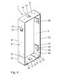
- FIGS. 1 to 4 illustrated mounting frame 1 is arranged in a wall 2 surrounded by a wall opening 3.
- the mounting frame 1 is arranged inside the wall opening 3, that he does not protrude over the wall 2. This means that a width B R of the mounting frame 1 is less than or equal to a width B M of the wall second
- the mounting frame 1 has a band-like outer frame 4, which rests with an outer side 5 flat against the wall opening 3.
- two band-like inner strips 7 are fastened by rivets.
- the inner strip 7 may also be connected by screws, gluing or other joining methods with the outer frame 4.
- the width B R of the mounting frame 1 is determined by the wall width of the outer frame 4.
- the inner strip 7 has a width B L , which is reduced compared to the width B R of the mounting frame 1.
- the inner strip 7 is arranged on the outer frame 4, that on both sides to openings of the mounting frame 1, a protrusion surface 38 of the outer frame 4 is provided. It is also possible, only one overhang area 38 between the outer frame 4 and the inner bar 7 provide.
- the projection surface 38 is in accordance with in the embodiment shown FIG. 3 1 mm.
- the protrusion surface 38 may also be, for example, more or less than 1 mm, in particular 3 mm.
- the extent of the overhang surface 38 is to be adapted to a ventilation grille to be attached to the mounting frame 1 such that the ventilation grille does not protrude beyond the mounting frame 1 into an interior space.
- the projection surface 38 thus defines a maximum stop depth for a ventilation grille to be used or a comparable cover in the wall thickness direction.
- the outer frame 4 has two identically formed band sections 8, which are essentially U-shaped and are connected to one another in a form-locking manner by means of a dovetail connection 9 and are positioned relative to one another.
- the inventive design of the outer frame 4 of the mounting frame 1 in particular a fast, straightforward and thus easy production is possible.
- the outer frame 4 can be prefabricated by a cutting process from a semi-finished sheet metal and in a subsequent bending-Abkanthabilit in the in FIG. 3 shown U-shape to be bent. Subsequently, the identically designed band sections 8 can be connected to each other at the dovetail connections 9 to the outer frame 4.
- This connection is positive and thus firm and resilient and also solvable, so that, for example, in the event of a necessary repair or disassembly as a result of a replacement operation, a disassembly of the outer frame 4 is easily possible.
- the outer frame 4 is additionally connected to one another, for example by riveting, a disassembly of the band sections 8 can also be destructive, ie by opening the riveted connection.
- the firmly connected to the outer frame 4 Inner strips 7 overlap the dovetail connections 9 and thus contribute to an additional stiffening and stabilization of the mounting frame 1 at.
- the outer frame 4 is made of stainless steel, is thus stainless and in particular, the mounting frame 1 so that sufficient stability for attachment of a ventilation grille.
- the inner bar 7 is made of steel.
- the strength and corrosion properties of the steel strip 7 are not as high as on the outer frame 4, so that in the illustrated embodiment, the inner strip 7 has been made of a structural steel such as St 37.
- a structural steel such as St 37.
- Such a material is stable, inexpensive and can be made, for example, from waste of the oven production, so that the inner strip 7 is produced in a resource-saving manner.
- a metallic sheet material is preferably used. But there are also high-strength and temperature-resistant plastics for forming the mounting frame 1 in principle conceivable.
- the mounting frame 1 has a rectangular or square cross section with vertical sides 10 and horizontal sides 11.
- wall tabs 12 are provided on the outer frame 4, by means of which the mounting frame 1 can be anchored to the wall opening 3.
- the wall tab 12 is integrally mounted on the outer frame 4 pivotally and can, as in FIG. 4 shown pivoted about a pivot axis 13 with respect to a sheet metal plane of the outer frame 4 become.
- the other wall tabs 12 in a non-pivoted state, as they are present after the production of the outer frame 4.
- This is introduced by a substantially rectangular open cutting contour 14 in the outer frame 4.
- the wall tabs 12 are each provided in one of the vertical sides 10 and horizontal sides 11 in the embodiment shown.
- the swung-wall brackets 12 may be connected directly to a mortar bed of the surrounding wall opening 3 or bolted through a hole in the respective wall tab 12 with the wall 2.
- the inner strips 7 are mounted in the embodiment shown in each case on the horizontal sides 11 substantially over the entire surface on the inner side 6 of the outer frame 4.
- the inner strip 7 on both sides integrally formed, from the inner bar 7 vertically wegeruitende bent portions 15.
- the bent portions 15 abut against the inner side 6 of the horizontal sides 11.
- an arrangement of the inner strips 7 at the front edges of the opposite sides 10 or 11 facilitates subsequent attachment of the ventilation grille, defines a stop depth in the wall thickness direction and represents a receptacle for different covers.
- the inner strips 7 each have two fastening tabs 16, which serve for fastening the ventilation grille to the mounting frame 1.
- the mounting tab 16 is integrally formed on the inner strip 7 and is similar to the wall tab 12 pivotable about a pivot axis 17 of a sheet metal plane of the inner strip 7 of the inner side 6 of the outer frame 4 away. Thus, the mounting tab 16 protrudes inward in the region of the wall opening 3.
- the mounting tab 16 is also bent around a parallel to the pivot axis 17 bending edge 18 such that a mounting portion 19 of the mounting tab 16 parallel to the Inner bar 7 is aligned.
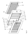
- FIG. 5 A second embodiment of the invention described. Structurally identical parts are given the same reference numerals as in the first embodiment, to the description of which reference is hereby made. Structurally different but functionally similar parts receive the same reference numerals with a following a.
- the main difference with respect to the first exemplary embodiment is the design of the inner strip 7a, which has a plurality of recesses 21 arranged at regular intervals along the horizontal side 11 on one end face 20.
- the recesses 21 are used for example for attachment of rod-shaped elements 22 or not shown sheet-like elements with tabs in the mounting frame 1a.
- FIG. 5 is further shown that with the mounting frame 1a according to the invention attachment of two ventilation grilles 23, 24 is possible.
- the ventilation grille 23, 24 are each placed on an end face 25 of the mounting frame 1a.
- the attachment of the ventilation grille 23, 24 on the mounting frame 1a is effected by a clamping elastic spring elements 26 on the mounting portions 19 of the fastening tabs 16 of the inner strip 7a.
- design of the protrusion surfaces 38 of the mounting frame 1a, ventilation grille 23, 24 different thicknesses on a front and a back mounted flush with the frame.
- the ventilation grille not by clamping special form-fitting to the mounting frame by, for example, the inner strip has several hook-eyelets, in which a corresponding ventilation grille can be mounted with correspondingly designed hook-projections.
- Ventilation grilles 23, 24 One function of the ventilation grilles 23, 24 is to prevent glimpse of the mounting frame 1a.
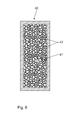
- a ventilation grille 23, 24 shown in FIG. 6 illustrated ventilation grille 40 can be used.
- the ventilation grille 40 is substantially similar to the ventilation grilles 23, 24 constructed with a peripheral frame and for securing the ventilation grille 40 to the mounting frame 1a provided, not shown spring elements.
- a grid surface 41 of the ventilation grille 40 has a plurality of irregularly arranged webs 42 which form a random pattern. Such a designed grid surface 41 is also referred to as Eisblumen-grid surface.
- the ventilation grille 40 also makes it possible to avoid an insight into the mounting frame 1a.
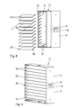
- FIG. 7 A third embodiment of the invention described. Structurally identical parts are given the same reference numerals as in the first two embodiments, to the description of which reference is hereby made. Structurally different, but functionally similar parts receive the same reference numerals with a trailing b.
- the inner strip 7b also in the third embodiment Recesses 21 for receiving the rod-shaped elements 22.
- receiving slots 27 for receiving lattice frame-shaped fixing elements 28 are additionally provided in the inner strip 7b of the mounting frame 1b. Alternatively or additionally, privacy elements can also be provided.
- the receiving slots 27 are each arranged parallel to one another and adjacent to the fastening tabs 16. In the embodiment shown according to FIG.
- the fixing elements 28 have the receiving slots 27 corresponding fixing webs 30 which are engageable with the receiving slots 27 for fastening the fixing elements 28 on the mounting frame 1b.
- FIGS. 8 and 9 A fourth embodiment of the invention is described.
- Structurally identical parts receive the same reference numerals as in the first embodiment, to the description of which reference is hereby made.
- Structurally different, but functionally similar parts receive the same reference numerals with a c.
- the essential difference of the mounting frame 1c with respect to the first embodiment is the arrangement of a plurality of groove-like depressions in the form of slots 31 in the inner strips 7c.
- the slots 31 extend obliquely to the vertical sides 10 and are open at the end face 25 of the inner strip 7c, so that plug-in blades 32 are inserted into the slots 31 from the end face 25 forth in the mounting frame 1c.
- Each plug-in blade 32 has lateral abutment shoulders 39, with which the plug-in blade 32 rests in the mounted state on the end face 25 of the inner strip 7c.
- the plug-in blade 32 has a width B s , which is reduced in relation to the width B L of the inner strip 7 c in the region of the slots 31. This means that by inserting the plug-in blade 32 in the slots 31, the plug-in blades 32 are elastically deformed and biased in the mounting frame 1 c are arranged. This avoids unintentional release of the plug-in blades 32 from the mounting frame 1c during operation.
- FIG. 9 the mounting frame 1c is shown with the inserted into the slots 31 plug-in blades 32 mounted state.
- a slot 31 in the inner strip 7c in such a way that it is opened on a second end face opposite the end face 25, so that a plug-in blade 32 also extends from the end face 25 opposite the end face into the mounting frame 1c can be inserted.
- the plug-in blades 32 are set at an inclination angle with respect to the fixing frame 1c such that a view through the fixing frame 1c is prevented.
- the mounting frame 1c allows a very good air flow behavior and at the same time prevents insight on arranged behind the plug-in blades 32 channels and / or devices.
- the plug-in blades 32 are connected directly to the mounting frame 1c.
- the fastening tabs can be omitted.
- FIGS. 10 to 12 A fifth embodiment of the invention is described. Structurally identical parts receive the same reference numerals as in the first four embodiments, the description of which reference is hereby made. Structurally different, but functionally similar parts receive the same reference numerals with a d followed. Significant difference compared to the first embodiment is that in the mounting frame 1d on the inner bar 7d each two suspension pins 33 are fixedly mounted. Furthermore, an insertion frame 34 is provided, which essentially has a cross-sectional shape corresponding to the attachment frame 1d.
- corresponding to the Ein theorystatten 33 corresponding Ein theorylaschen 35 are provided on the Einsetzrahmen 34, by means of which the Einsetzrahmen 34 can be connected to the suspension pins 33 with the mounting frame 1d.
- the suspension lugs 35 are substantially L-shaped, so that the insertion frame 34 is displaceable over a substantially horizontal guide portion 36 of the suspension lug 35 in a substantially vertical latching portion 37. In the latching portion 37 of the insertion frame 34 is engaged due to its weight and held on the suspension pins 33 fixed to the inner bar 7d and thus to the mounting frame 1d.
- the mounting frame 1 d can be modularly, easily and quickly converted if the requirements for a vorzu Fixdes in the wall opening 3 air guide element change.
- the accessibility of the wall opening is improved by the Einsetzrahmen 34, so that, for example, in the case of maintenance or cleaning a fast and direct removal of the plug-in blades 32 with the Einsetzrahmen 34 is made possible.
- the suspension pin 33 may be formed, for example, as a rivet, screw, bolt or the like. It is particularly advantageous if 33 pins or screws are used as a suspension pin, which are necessary for fastening the inner strip 7 d to the outer frame 4.
Landscapes
- Engineering & Computer Science (AREA)
- Chemical & Material Sciences (AREA)
- Combustion & Propulsion (AREA)
- Mechanical Engineering (AREA)
- General Engineering & Computer Science (AREA)
- Specific Sealing Or Ventilating Devices For Doors And Windows (AREA)
- Ventilation (AREA)
Applications Claiming Priority (1)
| Application Number | Priority Date | Filing Date | Title |
|---|---|---|---|
| DE202010002131U DE202010002131U1 (de) | 2010-02-09 | 2010-02-09 | Befestigungs-Rahmen für ein Lüftungsgitter |
Publications (2)
| Publication Number | Publication Date |
|---|---|
| EP2354697A2 true EP2354697A2 (fr) | 2011-08-10 |
| EP2354697A3 EP2354697A3 (fr) | 2012-04-04 |
Family
ID=43969435
Family Applications (1)
| Application Number | Title | Priority Date | Filing Date |
|---|---|---|---|
| EP11153130A Withdrawn EP2354697A3 (fr) | 2010-02-09 | 2011-02-03 | Cadre de fixation pour une grille d'aération |
Country Status (2)
| Country | Link |
|---|---|
| EP (1) | EP2354697A3 (fr) |
| DE (1) | DE202010002131U1 (fr) |
Cited By (2)
| Publication number | Priority date | Publication date | Assignee | Title |
|---|---|---|---|---|
| CN102635299A (zh) * | 2012-04-11 | 2012-08-15 | 广东明阳风电产业集团有限公司 | 通风过滤窗 |
| FR3009860A1 (fr) * | 2013-08-22 | 2015-02-27 | Dixneuf Atel | Dispositif de circulation d'air pour hotte de cheminee et hotte de cheminee equipee d'un tel dispositif |
Family Cites Families (7)
| Publication number | Priority date | Publication date | Assignee | Title |
|---|---|---|---|---|
| DE1777033U (de) * | 1957-03-26 | 1958-11-06 | Wilhelm Koetzner | Abdeck- und belueftungskasten fuer steigstrang-rohrbe- und -entlueftungsventile. |
| DE7013825U (de) * | 1970-04-15 | 1970-07-23 | Schaefer Gmbh Fritz | Lueftungsgitter aus kunststoff. |
| US4404990A (en) * | 1979-09-11 | 1983-09-20 | Prefco Products, Inc. | Economy, angle-blade damper kit |
| US5171184A (en) * | 1991-08-21 | 1992-12-15 | Press Mechanical, Inc. | Tensioned fire damper assembly and method |
| US5984776A (en) * | 1998-01-29 | 1999-11-16 | Berger; Brian K. | Register assembly for covering an air duct opening |
| KR20030036299A (ko) * | 2003-02-26 | 2003-05-09 | 엘지전자 주식회사 | 공기조화기용 벽 매입형 실외기 |
| CA2497636C (fr) * | 2004-02-18 | 2013-04-16 | Snyder National Corporation | Grille a registre et cadre de raccordement avec connexion detachable |
-
2010
- 2010-02-09 DE DE202010002131U patent/DE202010002131U1/de not_active Expired - Lifetime
-
2011
- 2011-02-03 EP EP11153130A patent/EP2354697A3/fr not_active Withdrawn
Non-Patent Citations (1)
| Title |
|---|
| None |
Cited By (3)
| Publication number | Priority date | Publication date | Assignee | Title |
|---|---|---|---|---|
| CN102635299A (zh) * | 2012-04-11 | 2012-08-15 | 广东明阳风电产业集团有限公司 | 通风过滤窗 |
| FR3009860A1 (fr) * | 2013-08-22 | 2015-02-27 | Dixneuf Atel | Dispositif de circulation d'air pour hotte de cheminee et hotte de cheminee equipee d'un tel dispositif |
| EP2843314A1 (fr) * | 2013-08-22 | 2015-03-04 | Les Ateliers Dixneuf | Dispositif de circulation d'air notamment pour hotte de cheminée et hotte de cheminée équipée d'un tel dispositif |
Also Published As
| Publication number | Publication date |
|---|---|
| DE202010002131U1 (de) | 2011-06-09 |
| EP2354697A3 (fr) | 2012-04-04 |
Similar Documents
| Publication | Publication Date | Title |
|---|---|---|
| DE202006009355U1 (de) | Filterlüfter mit einer Schnellbefestigungseinrichtung | |
| DE202009003138U1 (de) | Befestigungselement | |
| EP3566270B1 (fr) | Ensemble plaque de montage et procédé correspondant | |
| EP2631414A2 (fr) | Rail de guidage pour marquise verticale et marquise verticale | |
| DE10238445A1 (de) | Kühlergitter für ein Kraftfahrzeug | |
| EP2354697A2 (fr) | Cadre de fixation pour une grille d'aération | |
| CH707518B1 (de) | Metallzarge. | |
| EP2787265B1 (fr) | Pièce de cornière d'angle | |
| DE102013112761A1 (de) | Haltevorrichtung für ein Gehäuse und Verfahren zur Montage des Gehäuses unter Verwendung der Haltevorrichtung | |
| WO2014161962A1 (fr) | Réalisation d'un type de protection pour appareils électriques et électroniques, en particulier pour armoires de distribution | |
| EP2240651B1 (fr) | Dispositif de baguettes profilées | |
| DE102013015352B4 (de) | Blendenprofil zur Anbringung einer Abschlussblende an einem Ojekt, zum Beispiel einem Möbelstück und System, umfassend ein Blendenprofil, ein Objekt und eine Abschlussblende | |
| EP2523281A2 (fr) | Caniveau de câbles | |
| EP3483047B1 (fr) | Dispositif de retenue pour un véhicule utilitaire, agencement d'un rancher doté d'un dispositif de retenue, véhicule utilitaire, procédé de fabrication d'un dispositif de retenue et procédé de montage d'un dispositif de retenue sur un rancher | |
| DE102017114129B4 (de) | Montageplattenanordnung für den Innenausbau eines Schaltschranks und ein entsprechender Schaltschrank | |
| DE202012009059U1 (de) | Luftauslass | |
| DE102010015117A1 (de) | Isolierglasscheibe | |
| EP2145135B1 (fr) | Parois latérales d'un logement pour hotte aspirante, logement pour hotte aspirante et hotte aspirante correspondante | |
| DE202010005603U1 (de) | Fassadensystem, mit Reparaturhalter | |
| DE102006056599B3 (de) | Faltenbalg sowie Verfahren zur Montage eines Faltenbalgs an einem Sitzrahmen | |
| DE202010005075U1 (de) | Isolierglasscheibe | |
| DE102004048055A1 (de) | Kabeleinführungsvorrichtung für eine Gehäusewand | |
| EP4234870A1 (fr) | Innenfensterbanksystem | |
| EP3095947B1 (fr) | Systeme de retenue de seuil adapte a de nombreuses geometries de dormant | |
| EP3097338B1 (fr) | Boîtier pour moniteur de plafond |
Legal Events
| Date | Code | Title | Description |
|---|---|---|---|
| PUAI | Public reference made under article 153(3) epc to a published international application that has entered the european phase |
Free format text: ORIGINAL CODE: 0009012 |
|
| AK | Designated contracting states |
Kind code of ref document: A2 Designated state(s): AL AT BE BG CH CY CZ DE DK EE ES FI FR GB GR HR HU IE IS IT LI LT LU LV MC MK MT NL NO PL PT RO RS SE SI SK SM TR |
|
| AX | Request for extension of the european patent |
Extension state: BA ME |
|
| PUAL | Search report despatched |
Free format text: ORIGINAL CODE: 0009013 |
|
| AK | Designated contracting states |
Kind code of ref document: A3 Designated state(s): AL AT BE BG CH CY CZ DE DK EE ES FI FR GB GR HR HU IE IS IT LI LT LU LV MC MK MT NL NO PL PT RO RS SE SI SK SM TR |
|
| AX | Request for extension of the european patent |
Extension state: BA ME |
|
| RIC1 | Information provided on ipc code assigned before grant |
Ipc: E06B 1/12 20060101ALI20120228BHEP Ipc: F24F 13/08 20060101AFI20120228BHEP |
|
| 17P | Request for examination filed |
Effective date: 20121004 |
|
| STAA | Information on the status of an ep patent application or granted ep patent |
Free format text: STATUS: THE APPLICATION IS DEEMED TO BE WITHDRAWN |
|
| 18D | Application deemed to be withdrawn |
Effective date: 20150901 |