EP2354732A2 - Tür eines Kühl- und/oder Gefriergerätes - Google Patents
Tür eines Kühl- und/oder Gefriergerätes Download PDFInfo
- Publication number
- EP2354732A2 EP2354732A2 EP11000589A EP11000589A EP2354732A2 EP 2354732 A2 EP2354732 A2 EP 2354732A2 EP 11000589 A EP11000589 A EP 11000589A EP 11000589 A EP11000589 A EP 11000589A EP 2354732 A2 EP2354732 A2 EP 2354732A2
- Authority
- EP
- European Patent Office
- Prior art keywords
- door
- rack
- compartment
- web
- webs
- Prior art date
- Legal status (The legal status is an assumption and is not a legal conclusion. Google has not performed a legal analysis and makes no representation as to the accuracy of the status listed.)
- Granted
Links
Images



Classifications
-
- F—MECHANICAL ENGINEERING; LIGHTING; HEATING; WEAPONS; BLASTING
- F25—REFRIGERATION OR COOLING; COMBINED HEATING AND REFRIGERATION SYSTEMS; HEAT PUMP SYSTEMS; MANUFACTURE OR STORAGE OF ICE; LIQUEFACTION SOLIDIFICATION OF GASES
- F25D—REFRIGERATORS; COLD ROOMS; ICE-BOXES; COOLING OR FREEZING APPARATUS NOT OTHERWISE PROVIDED FOR
- F25D23/00—General constructional features
- F25D23/02—Doors; Covers
- F25D23/04—Doors; Covers with special compartments, e.g. butter conditioners
-
- F—MECHANICAL ENGINEERING; LIGHTING; HEATING; WEAPONS; BLASTING
- F25—REFRIGERATION OR COOLING; COMBINED HEATING AND REFRIGERATION SYSTEMS; HEAT PUMP SYSTEMS; MANUFACTURE OR STORAGE OF ICE; LIQUEFACTION SOLIDIFICATION OF GASES
- F25D—REFRIGERATORS; COLD ROOMS; ICE-BOXES; COOLING OR FREEZING APPARATUS NOT OTHERWISE PROVIDED FOR
- F25D25/00—Charging, supporting, and discharging the articles to be cooled
- F25D25/04—Charging, supporting, and discharging the articles to be cooled by conveyors
Definitions
- the present invention relates to a door of a refrigerator and / or freezer with at least one arranged on the inside of the door door racks, wherein the door racks is designed to be movable relative to the inside of the door so that it can be locked at different positions of the inside of the door.
- Such doors with arranged on the inside or inside door door compartments are known in numerous different embodiments.
- conventional door racks have the disadvantage that they often have a relatively complicated mechanism by means of which the locking of the door racks takes place at the desired position of the inside of the door.
- known door cabinets if necessary, there is a further disadvantage in that they are completely removed for the purpose of adjustment and then mounted in a new position offset in the vertical direction.
- the goods should first be removed, the Absteller be offset in height and then the goods are given back. This type of height adjustment of a door compartment is relatively cumbersome and therefore not user-friendly.
- the present invention is therefore the object of developing a door of the type mentioned in that the door rack is adjustable in a height direction in a comparatively simple manner.
- At least one guide in the form of at least one arranged on the inside of the door, preferably vertically extending web is provided on the inside of the door.
- the one or more webs form a guide for the or the door racks, in its adjustment.
- a preferably vertically arranged web is arranged on the inside of the door.
- the invention also includes the case that more than one web, preferably a plurality of parallel webs, such as two parallel webs are arranged on the inside of the door.
- the web or webs preferably extend in the vertical direction.
- the one or more webs or another portion of the inside of the door has first locking means which cooperate with arranged on the door racks second locking means such that the door racks is locked by the first and the second locking means in the desired position.
- the door racks or the second means a portion of the inner door, and preferably the one or more webs and / or the first means, at least partially engages behind, so that accidental tilting or falling out of the door compartment or the goods located thereon prevented becomes.
- the inside of the door and the door rack is designed so that a limited to the vertical direction height adjustment without the installation or the use of additional parts is achieved.
- the first means of the web or the webs not only form locking means, by means of which the door racks can be locked in the desired vertical position, but also form the said guide for the vertical adjustment of the door compartment.
- the second means are formed by a part integrally connected to the door racks, for example by a directly molded onto the door plate part. It is also conceivable, however, for the second means to be formed by a part connected to the door racks, but not integrally connected thereto.
- the web or webs have a front side facing the door racks, a rear side remote from the latter and an outer and inner side, and that the first means are arranged on one or more of these sides.
- said first means are formed by nubs, which are arranged for example on the inside of the web or on the mutually facing inner sides of the webs and which are spaced apart in the vertical direction to a certain extent, which is the grid for the positioning of the door racks forms.
- any other projections or recesses may be provided in the web or in the webs.
- the door rack has a groove extending in the adjustment direction of the door compartment, which engages behind the web or the first means disposed thereon or another area of the door inner side.
- the web or another region of the inside of the door has a groove extending in the adjustment direction of the door compartment, in which a projection of the door compartment engages.
- the door racks have a vertical groove which engages behind arranged on the web nubs.
- These knobs thus have not only the function of locking the door compartment in a desired position, but also the function of the leadership of the door compartment during adjustment and also serve as Kippêt against tilting or falling of the door compartment of the inner door.
- the inner door or the one or more webs and the door racks are arranged so that in certain positions of the door compartment removal of the door compartment, for example, for cleaning or to replace it is possible.
- the second means are formed by a movable tab, by a slider, by a rotatable arrangement, in particular by a rotary lever or by a device exerting a clamping force.
- the door rack has at least one, preferably two recesses, which at least partially surround the web or the webs of the inner door. This leads to an improvement of the leadership of the door compartment on the webs or on the webs. It is particularly advantageous that the recesses are formed by sections of the door compartment, which have a smaller height than the door rack itself. This has the advantage that the probability of tilting the door compartment is reduced.
- At least one further guide means preferably at least one groove is provided for guiding the door compartment and / or that the first means arranged on or in the guide means, in particular on or in the groove are.
- the arrangement of a further guide means can be used in the case of a web or in the case of multiple webs.
- first and second means are designed such that the locking of the door compartment is released automatically by lifting the door compartment.
- the invention relates to a refrigerator and / or freezer with at least one refrigerated interior, which can be closed by at least one door, wherein the door is designed according to one of claims 1 to 9.
- FIG. 1 shows in a perspective view of a door racks 10, which is locked and guided on two vertically extending, and spaced apart in the width direction webs 20.
- nubs 22 On the mutually facing inner side of the webs 20 are nubs 22, which are spaced apart in the vertical direction, ie in the adjustment of the door compartment 10.
- These knobs 22 of the inner door take over both the guides of the height adjustment of the door compartment 10 and the locking positions in the vertical direction.
- a variable height adjustment of the door racks 10 is possible.
- the nubs 22 can also be arranged at a different location, for example on the outside of the webs 20.
- This embodiment of the invention has the advantage that no additional guide rails or other attachments are required to enable one hand, a height adjustment of the door compartment and on the other hand to form a guide and securing the door compartment 10 against tipping or falling.
- the door rack 10 has a lateral, vertically extending groove 12, whose width is designed so that the knobs 22 of the webs 20 can be received in the groove 12.
- the door racks 10 thus engages behind one of the groove walls 12, the knobs 22 of the webs 20th
- the nubs 22 of the webs 20 form in the embodiment shown here, the first means for locking the door racks.
- the door racks 10 themselves have second means, which cooperate with the first means of the webs to achieve the desired locking in the height direction.
- the locking is effected by a movable part which is supported on the knobs 22.
- This movable part forms the second means according to the invention, which cooperate with the first means.
- This moving part is molded in the simplest case directly to the door rack 10. However, it can also be used as a separate element for locking.
- FIG. 2 shows a door racks with molded locking tab 40, the ArretsammlungsSullivan, as in FIG. 2 , right representation visible, rests on top of a knob 22 and holds the door rack 10 in this way.
- the door rack is usually lifted slightly and the locking tab 40 is disengaged, d. H. adjusted so that it no longer rests on the studs 22.
- the door rack 10 can then be adjusted vertically.
- the locking tab 40 is manually or z. B. brought by a spring or the like back into the engaged position with the knobs 22. As a result, the door rack is fixed in height position.
- the second means by an integral with the door racks 10 element, as in FIG. 2 form visible tab.
- an additional part such as a slider or a rotary lever, which is in communication with the door racks 10 and which is supported in the locked state on the knobs 22.
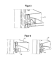
- FIG. 3 shows a schematic side view of a slider 42 which is vertically movable in the direction of the arrow to the plane of the inside of the door and depending on the position allows vertical adjustment of the door compartment 10 or prevented.
- FIG. 4 shows an arrangement with a rotary lever 44 in the adjustment position (left view) and in the locking position (right view).
- the rotary lever is rotatable about an axis perpendicular to the plane of the inside of the door axis and has a locking portion which rests in the locking position on top of the studs 22, as is apparent from FIG. 4 , right-hand illustration emerges. In this position, the door rack is accordingly fixed in its vertical position.
- FIG. 5 two door racks, of which the upper represents a standard door racks, which is not designed to be vertically displaceable, but must be removed to its height adjustment, and as a lower door racks 10 a door rack according to the invention.
- the operation of the height adjustment of the door racks is improved when the ratio of the guide width to the guide length of the door racks is optimized.
- common height adjustments may occur due to an unfavorable geometry ratio (width / height of the guide) in an adjustment of the door compartment to tilting.
- the leadership of the door compartment is realized by a comparatively narrow rib or groove.
- FIG. 6 shows on both sides of the door racks 10 in one piece with this running recesses, which can be made circular in cross-section part.
- These recesses 16 may surround the webs 20 at least partially, and in the embodiment shown here at the front and on the side edges and thus serve as a further guide.
- the webs 20 of the inner door then have a double function, ie they serve as a guide of the door racks 10 and as a sealing labyrinth. Due to this optimized guidance of the door racks 10, small grid spacings are possible without skewed shelves 10.
- a guide groove is arranged on the inside of the door, in which a projection of the door compartment 10 runs.
- a guide groove is arranged on the inside of the door, in which a projection of the door compartment 10 runs.
- FIG. 7 seen.
- a guide groove 50 which is arranged vertically, and in which a projection of the door compartment 10 runs.
- the configuration of the first and second means is largely arbitrary, as long as it is ensured that by the interaction of a fixation the door compartment 10 is achieved in a vertical position.
- a continuous web 20 may be used, which has recesses for fixing the height adjustment. This has the advantage that an optically continuous profile can be provided.
- the recesses for the purpose of locking can be arranged on the web 20 or on the groove base or on the surface of the inner door.
- FIG. 8 shows such an embodiment in which the webs 20 has no projections, but on the back or on their mutually facing side depressions, engage in the projections of the door racks or their second means.
- clamping wedge or a pinch roller or the like which bring about the fixing of the door racks over an inclined plane.
- the clamping can be done either on the web 20 or a groove of the inner door.
- the advantage of a clamping device of the door compartment 10 on the inside of the door provides a backlash-free attachment and has the advantage that the clamping force increases proportionally with the load.
- the function of the clamping can also be applied to the knob geometry or other geometries for fixing the door compartment.
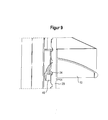
- FIG. 9 shows an embodiment with a clamping wedge 46th
- the clamping wedge 46 is movable relative to the door rack 10 and is released when lifting the door compartment 10 and pulled back over the inclined surface of the door compartment 10. After pulling out of the clamping wedge 46 from the locking recess 24 of the web 20 of the door rack can be adjusted in height. For fixation of the door compartment, the clamping wedge 46 must be manually pushed into the locking recess. This condition is off FIG. 9 seen.
- the clamping wedge is supported on the web 20 or on another part of the inner container and is loaded by the door racks so that the friction force fixes the clamping wedge and thus the door racks in the desired position on the web or on the inner container.
- the clamping wedge may be arranged between a part of the door compartment, which may also have a chamfer, and the web or the inner container, as is apparent from FIG. 9 evident.
- the clamping wedge for example, either by the in FIG. 9 shown latching recess 24 or be fixed by the weight of the door compartment.
- this part of the door compartment and the clamping wedge can be located on the side of the web or the like, which turned to the inner container and / or facing away from the actual storage area of the door compartment.
- a pawl or the like in particular a sprung pawl or the like is provided, which acts on the door racks so that tilting largely or completely prevented.
- this anti-tilt device is designed so that tilting is prevented when the door rack is adjusted in position.
Landscapes
- Engineering & Computer Science (AREA)
- Chemical & Material Sciences (AREA)
- Combustion & Propulsion (AREA)
- Physics & Mathematics (AREA)
- Mechanical Engineering (AREA)
- Thermal Sciences (AREA)
- General Engineering & Computer Science (AREA)
- Refrigerator Housings (AREA)
Abstract
Description
- Die vorliegende Erfindung betrifft eine Tür eines Kühl- und/oder Gefriergerätes mit wenigstens einem an der Türinnenseite angeordneten Türabsteller, wobei der Türabsteller relativ zu der Türinnenseite derart bewegbar ausgeführt ist, dass er an unterschiedlichen Positionen der Türinnenseite arretierbar ist.
- Derartige Türen mit an deren Innenseite bzw. Innentür angeordneten Türabstellern sind in zahlreichen unterschiedlichen Ausführungsformen bekannt. Herkömmliche Türabsteller weisen jedoch den Nachteil auf, dass sie häufig einen vergleichsweise komplizierten Mechanismus aufweisen, mittels dessen die Arretierung der Türabsteller an der gewünschten Position der Türinnenseite erfolgt. Bei bekannten Türabstellern besteht gegebenenfalls ein weiterer Nachteil darin, dass diese zum Zwecke der Verstellung komplett abgenommen und dann in Höhenrichtung versetzt an neuer Position eingehängt werden. Bei Beladung der Türabsteller mit hohen Waren bzw. bei Türabstellern, die keine Rückwand aufweisen, sollte die Ware zunächst entnommen werden, der Absteller in der Höhe versetzt werden und dann die Ware wieder eingeräumt werden. Diese Art der Höhenverstellung eines Türabstellers ist vergleichsweise umständlich und daher nicht benutzerfreundlich.
- Der vorliegenden Erfindung liegt daher die Aufgabe zugrunde, eine Tür der eingangs genannten Art dahingehend weiterzubilden, dass der Türabsteller auf vergleichsweise einfache Art und Weise in Höhenrichtung verstellbar ist.
- Diese Aufgabe wird dadurch gelöst, dass an der Türinnenseite wenigstens eine Führung in Form von wenigstens einem an der Türinnenseite angeordneten, vorzugsweise vertikal verlaufenden Steg vorgesehen ist. Der oder die Stege bilden für den oder die Türabsteller eine Führung, bei dessen Verstellung.
- Grundsätzlich ist es somit denkbar, dass an der Türinnenseite ein vorzugsweise vertikal angeordneter Steg angeordnet ist. Von der Erfindung ist jedoch auch der Fall umfasst, dass mehr als ein Steg, vorzugsweise mehrere parallele Stege, wie beispielsweise zwei parallele Stege an der Türinnenseite angeordnet sind.
- Der oder die Stege verlaufen vorzugsweise in vertikaler Richtung.
- Des Weiteren ist vorgesehen, dass der oder die Stege oder auch ein anderer Bereich der Türinnenseite erste Arretierungsmittel aufweist, die mit an dem Türabsteller angeordneten zweiten Arretierungsmitteln derart zusammenwirken, dass der Türabsteller durch die ersten und die zweiten Arretierungsmittel in der gewünschten Position arretiert wird. Weiterhin ist vorgesehen, dass der Türabsteller oder die zweiten Mittel einen Bereich der Innentür, und zwar vorzugsweise den oder die Stege und/oder die ersten Mittel, wenigstens bereichsweise hintergreift, so dass ein versehentliches Kippen oder Herausfallen des Türabstellers bzw. der darauf befindlichen Ware verhindert wird.
- Vorzugsweise ist die Türinnenseite sowie der Türabsteller so ausgeführt, dass eine auf die Vertikalrichtung eingeschränkte Höhenverstellung ohne den Einbau bzw. die Zuhilfenahme von Zusatzteilen erreicht wird. Denkbar ist es, dass die ersten Mittel des Steges bzw. der Stege nicht nur Arretierungsmittel bilden, mittels derer der Türabsteller in der gewünschten vertikalen Position arretierbar ist, sondern zusätzlich die genannte Führung für die Vertikalverstellung des Türabstellers bilden.
- In weiterer Ausgestaltung der Erfindung ist vorgesehen, dass die zweiten Mittel durch ein mit dem Türabsteller einteilig verbundenes Teil, beispielsweise durch ein direkt an den Türabteller angespritztes Teil gebildet werden. Denkbar ist es jedoch auch, dass die zweiten Mittel durch ein mit dem Türabsteller in Verbindung stehendes, jedoch nicht einteilig mit diesem verbundenen Teil gebildet werden.
- In weiterer Ausgestaltung der Erfindung ist vorgesehen, dass der oder die Stege eine zum Türabsteller gerichtet Vorderseite, eine von diesem abgewandte Rückseite und eine Außen- und Innenseite aufweisen und dass die ersten Mittel an einer oder mehrerer dieser Seiten angeordnet sind. Denkbar ist es beispielsweise, dass die genannten ersten Mittel durch Noppen gebildet werden, die beispielsweise auf der Innenseite des Steges bzw. auf den einander zugewandten Innenseiten der Stege angeordnet sind und die in vertikaler Richtung in einem bestimmten Maß voneinander beabstandet sind, das das Raster für die Positionierung der Türabsteller bildet.
- Grundsätzlich sind auch davon abweichende Ausführungen möglich, wie beispielsweise die Anordnung von Noppen auf der Außenseite des Steges bzw. auf den voneinander abgewandten Außenseiten der Stege.
- Statt Noppen können selbstverständlich auch beliebige andere Vorsprünge oder auch Vertiefungen in dem Steg bzw. in den Stegen vorgesehen sein.
- In weiterer Ausgestaltung der Erfindung ist vorgesehen, dass der Türabsteller eine in Verstellrichtung des Türabstellers verlaufende Nut aufweist, die den Steg oder die daran angeordneten ersten Mittel oder einen anderen Bereich der Türinnenseite hintergreift. Grundsätzlich ist es ebenfalls denkbar, dass der Steg oder ein anderer Bereich der Türinnenseite eine in Verstellrichtung des Türabstellers verlaufende Nut aufweist, in die ein Vorsprung des Türabstellers eingreift.
- Denkbar ist es beispielsweise somit, dass der Türabsteller eine vertikale Nut aufweist, die an dem Steg angeordnete Noppen hintergreift. Diese Noppen haben somit nicht nur die Funktion der Arretierung des Türabstellers in einer gewünschten Position, sondern auch die Funktion der Führung des Türabstellers beim Verstellvorgang und dienen zudem als Kippsicherung gegen das Kippen oder Abfallen des Türabstellers von der Innentür.
- Grundsätzlich kann vorgesehen sein, dass die Innentür bzw. der oder die Stege sowie der Türabsteller so angeordnet sind, dass in bestimmten Positionen des Türabstellers ein Abnehmen des Türabstellers beispielsweise für Reinigungszwecke oder zu dessen Austausch möglich ist.
- In weiterer Ausgestaltung der Erfindung ist vorgesehen, dass die zweiten Mittel durch eine bewegbare Lasche, durch einen Schieber, durch eine drehbare Anordnung, insbesondere durch einen Drehhebel oder durch eine eine Klemmkraft ausübende Einrichtung gebildet werden. Auch eine Kombination dieser exemplarisch aufgezählten zweiten Mittel ist denkbar.
- In weiterer Ausgestaltung der Erfindung ist vorgesehen, dass der Türabsteller wenigstens eine, vorzugsweise zwei Ausnehmungen aufweist, die den Steg bzw. die Stege der Innentür zumindest teilweise umgreifen. Dies führt zu einer Verbesserung der Führung des Türabstellers an dem Stege bzw. an den Stegen. Besonders vorteilhaft ist es, dass die Ausnehmungen durch Abschnitte des Türabstellers gebildet werden, die eine geringere Höhe aufweisen als der Türabsteller selbst. Dies hat den Vorteil, dass die Wahrscheinlichkeit für ein Verkanten des Türabstellers verringert ist.
- In weiterer Ausgestaltung der Erfindung ist vorgesehen, dass beispielsweise zwischen den Stegen wenigstens ein weiteres Führungsmittel, vorzugsweise wenigstens eine Nut, zur Führung des Türabstellers vorgesehen ist und/oder dass die ersten Mittel an oder in den Führungsmitteln, insbesondere an oder in der Nut angeordnet sind. Die Anordnung eines weiteren Führungsmittels kann im Falle von einem Steg oder auch im Falle von mehreren Stegen zum Einsatz kommen.
- Denkbar ist es beispielsweise, an der Türinnenseite eine vertikale Führungsnut anzuordnen, in der ein Vorsprung des Türabstellers läuft. Auch die umgekehrte Anordnung ist denkbar, die darin besteht, dass das Führungsmittel an der Innentür durch einen Vorsprung gebildet wird, der in einer Nut des Türabstellers läuft.
- In weiterer Ausgestaltung der Erfindung ist vorgesehen, dass die ersten und zweiten Mittel derart ausgeführt sind, dass die Arretierung des Türabstellers durch ein Anheben des Türabstellers selbsttätig gelöst wird.
- Die Erfindung betrifft schließlich ein Kühl- und/oder Gefriergerät mit wenigstens einem gekühlten Innenraum, der durch zumindest eine Tür verschließbar ist, wobei die Tür nach einem der Ansprüche 1 bis 9 ausgeführt ist.
- Weitere Einzelheiten und Vorteile der Erfindung werden anhand eines in der Zeichnung dargestellten Ausführungsbeispiels näher beschrieben.
- Es zeigen:
- Figur 1:
- eine perspektivische Ansicht eines Türabstellers mit einem Bereich der Innentür in einer ersten Ausgestaltung der vorliegenden Erfindung,
- Figur 2:
- eine perspektivische Seitenansicht des Türabstellers mit vertikaler Führungsnut und Arretierungslasche im abgenommenen und im eingehängten Zustand,
- Figur 3:
- eine perspektivische Seitenansicht des Türabstellers im eingehängten Zustand mit einem separaten Schieber als Arretierungsmittel,
- Figur 4:
- unterschiedliche perspektivische Seitenansichten des Türabstellers mit einem Drehhebel als Arretierungsmittel,
- Figur 5:
- eine perspektivische Ansicht auf zwei an der Innenseite der Tür eingehängte Türabsteller, von denen einer erfindungsgemäß ausgeführt ist,
- Figur 6:
- eine perspektivische Ansicht von schräg oben auf einen Türabsteller im eingehängten Zustand,
- Figur 7:
- eine perspektivische Ansicht auf einen Türabsteller mit einer an der Innenseite der Tür angeordneten Führungsnut,
- Figur 8:
- eine perspektivische Ansicht eines Türabstellers im an die Innenseite der Tür eingehängten Zustand, wobei der Steg der Innentür Rastvertiefungen aufweist und
- Figur 9:
- eine perspektivische Seitenansicht eines Türabstellers im eingehängten Zustand mit Vertiefungen am Steg der Innenseite der Tür und einem als Klemmkeil ausgeführten Arretierungsmittel.
-
Figur 1 zeigt in einer perspektivischen Ansicht einen Türabsteller 10, der an zwei vertikal verlaufenden, und in Breitenrichtung voneinander beabstandeten Stegen 20 arretiert und geführt ist. Auf der einander zugewandten Innenseite der Stege 20 befinden sich Noppen 22, die in vertikaler Richtung, d. h. in Verstellrichtung des Türabstellers 10 voneinander beabstandet sind. Diese Noppen 22 der Innentür übernehmen sowohl die Führungen der Höhenverstellung des Türabstellers 10 als auch die Rastpositionen in Höhenrichtung. Durch im Raster an der Innentür geformte Noppen 22 ist eine variable Höhenverstellung der Türabsteller 10 möglich. - Die in
Figur 1 dargestellte Anordnung der Noppen 22 ist exemplarisch. Grundsätzlich können die Noppen 22 auch an anderer Stelle, beispielsweise an der Außenseite der Stege 20 angeordnet sein. - Diese Ausgestaltung der Erfindung bringt den Vorteil mit sich, dass keine zusätzlichen Führungsleisten oder andere Anbauteile erforderlich sind, um einerseits eine Höhenverstellung des Türabstellers zu ermöglichen und andererseits eine Führung und Sicherung des Türabstellers 10 gegen Kippen oder Herabfallen zu bilden.
- Wie dies aus
Figur 2 hervorgeht, besitzt der Türabsteller 10 eine seitliche, vertikal verlaufende Nut 12, deren Breite so ausgestaltet ist, dass die Noppen 22 der Stege 20 in der Nut 12 aufgenommen werden können. Der Türabsteller 10 hintergreift somit mit einer der Nutwandungen 12 die Noppen 22 der Stege 20. - Dies ermöglicht ein Verstellen des Türabstellers 10 in der vertikalen Richtung.
- Die Noppen 22 der Stege 20 bilden in dem hier dargestellten Ausführungsbeispiel die ersten Mittel zur Arretierung der Türabsteller.
- Die Türabsteller 10 selbst weisen zweite Mittel auf, die mit den ersten Mitteln der Stege zusammenwirken, um die gewünschte Arretierung in Höhenrichtung zu erreichen.
- Vorzugsweise wird die Arretierung durch ein bewegliches Teil bewirkt, das sich auf den Noppen 22 abstützt. Dieses bewegliche Teil bildet die erfindungsgemäßen zweiten Mittel, die mit den ersten Mitteln zusammenwirken.
- Dieses bewegliche Teil wird im einfachsten Fall direkt an den Türabsteller 10 angespritzt. Es kann jedoch auch als separates Element zur Arretierung eingesetzt werden.
-
Figur 2 zeigt einen Türabsteller mit angespritzter Arretierungslasche 40, die im Arretierungszustand, wie ausFigur 2 , rechte Darstellung ersichtlich, oben auf einer Noppe 22 aufliegt und auf diese Weise den Türabsteller 10 hält. - Beim Verstellvorgang wird üblicherweise der Türabsteller leicht angehoben und die Arretierungslasche 40 außer Eingriff gebracht, d. h. so verstellt, dass sie nicht mehr auf den Noppen 22 aufliegt. Der Türabsteller 10 kann dann vertikal verstellt werden. Nach dem Verstellvorgang wird die Arretierungslasche 40 manuell oder z. B. durch eine Feder oder dergleichen wieder in die Eingriffsposition mit den Noppen 22 gebracht. Dadurch ist der Türabsteller in Höhenposition fixiert.
- Wie oben ausgeführt, ist es nicht zwingend erforderlich, die zweiten Mittel durch ein mit dem Türabsteller 10 einteilig ausgeführtes Element, wie die in
Figur 2 ersichtliche Lasche auszubilden. Grundsätzlich ist es ebenfalls denkbar, ein Zusatzteil, wie beispielsweise einen Schieber oder einen Drehhebel zu verwenden, der mit dem Türabsteller 10 in Verbindung steht und der sich im arretierten Zustand auf den Noppen 22 abstützt. -
Figur 3 zeigt in einer schematischen Seitenansicht einen Schieber 42, der vertikal zur Ebene der Türinnenseite in Pfeilrichtung bewegbar ist und je nach Position eine vertikale Verstellung des Türabstellers 10 ermöglicht oder verhindert. -
Figur 4 zeigt eine Anordnung mit einem Drehhebel 44 in der Verstellposition (linke Darstellung) und in der Arretierungsposition (rechte Darstellung). Der Drehhebel ist um eine zur Ebene der Türinnenseite senkrecht verlaufende Achse verdrehbar und weist einen Arretierungsabschnitt auf, der in der Arretierungsposition oben auf den Noppen 22 aufliegt, wie dies ausFigur 4 , rechte Darstellung hervorgeht. In dieser Position wird der Türabsteller dementsprechend in seiner vertikalen Position fixiert. - Bei entsprechender Abstimmung der Innentürgeometrie und der Türstellereinhängung kann in bzw. an ein- und derselben Tür neben den höhenverstellbaren Absteliern gemäß der vorliegenden Erfindung auch ein Standardtürabsteller eingehängt werden, der zur Höhenverstellung ein- und ausgehängt werden muss. Eine solche Ausgestaltung bietet die Möglichkeit, in ein- und derselben Tür differenzierte bzw. gemischte Ausstattungen bezüglich der Höhenverstellung anzubieten.
- So zeigt
Figur 5 zwei Türabsteller, von denen der obere einen Standardtürabsteller darstellt, der nicht vertikal verschieblich ausgeführt ist, sondern zu seiner Höhenverstellung abgenommen werden muss, und als unteren Türabsteller 10 einen erfindungsgemäßen Türabsteller. - Die Bedienung der Höhenverstellung der Türabsteller wird verbessert, wenn das Verhältnis aus Führungsbreite zu Führungslänge der Türabsteller optimiert wird. Bei gängigen Höhenverstellungen kann es aufgrund eines ungünstigen Geometrieverhältnisses (Breite/Höhe der Führung) bei einem Verstellen des Türabstellers zu einem Verkanten kommen.
- Um diesen Nachteil zu beheben, kann vorgesehen sein, dass die Führung des Türabstellers durch eine vergleichsweise schmale Rippe bzw. Nut realisiert wird.
-
Figur 6 zeigt beidseitig an dem Türabsteller 10 einteilig mit diesem ausgeführte Ausnehmungen, die im Querschnittteil kreisförmig ausgeführt sein können. Diese Ausnehmungen 16 können die Stege 20 zumindest teilweise, und in dem hier dargestellten Ausführungsbeispiel frontseitig und an den Seitenflanken umgreifen und dienen somit als weitere Führung. Die Stege 20 der Innentür haben dann eine Doppelfunktion, d. h. sie dienen als Führung der Türabsteller 10 und als Dichtlabyrinth. Durch diese optimierte Führung der Türabsteller 10 sind geringe Rasterabstände ohne schiefstehende Absteller 10 möglich. - Die Führung der Türabsteller 10 kann weiter dadurch verbessert werden, dass beispielsweise eine Führungsnut auf der Innenseite der Tür angeordnet ist, in der ein Vorsprung des Türabstellers 10 läuft. Eine solche Ausgestaltung ist aus
Figur 7 ersichtlich. Hier verläuft in einem Bereich zwischen den beiden Stegen 20 eine vorzugsweise mittig angeordnete Führungsnut 50, die vertikal angeordnet ist, und in der ein Vorsprung des Türabstellers 10 läuft. - Wie ausgeführt, ist die Ausgestaltung der ersten und zweiten Mittel weitgehend beliebig, so lange sichergestellt ist, dass durch deren Zusammenwirken eine Fixierung des Türabstellers 10 in vertikaler Position erreicht wird. Anstatt der in den obigen Ausführungsbeispielen dargestellten Noppen 22 der Stege 20 kann auch ein durchgehender Steg 20 verwendet werden, der Vertiefungen zur Fixierung für die Höhenverstellung aufweist. Dies weist den Vorteil auf, dass ein optisch durchgängiges Profil bereitgestellt werden kann. Die Vertiefungen zum Zwecke der Verrastung können an dem Steg 20 oder auch am Nutgrund oder auch an der Fläche der Innentür angeordnet sein.
-
Figur 8 zeigt eine solche Ausführungsform, bei der die Stege 20 keine Vorsprünge, sondern auf deren Rückseite oder auf deren zueinander gewandte Seitenvertiefungen aufweist, in die Vorsprünge der Türabsteller bzw. deren zweite Mittel eingreifen. - Neben den oben dargestellten Möglichkeiten der Ausführungen der zweiten Mittel ist es auch denkbar, die Fixierung der Türabsteller 10 durch eine eine Klemmkraft ausübende Einrichtung 46 zu bilden.
- Denkbar ist die Verwendung eines Klemmkeils oder einer Klemmrolle oder dergleichen, die über eine schiefe Ebene die Fixierung der Türabsteller herbeiführen. Die Klemmung kann entweder auf den Steg 20 oder eine Nut der Innentür erfolgen. Der Vorteil einer Klemmeinrichtung des Türabstellers 10 auf der Innenseite der Tür bietet eine spielfreie Befestigung und bringt den Vorteil mit sich, dass die Klemmkraft proportional mit der Beladung zunimmt. Die Funktion der Klemmung kann auch bei der Noppengeometrie oder anderen Geometrien zur Fixierung des Türabstellers angewendet werden.
-
Figur 9 zeigt eine Ausführung mit einem Klemmkeil 46. - Der Klemmkeil 46 ist relativ zu dem Türabsteller 10 bewegbar und wird beim Anheben des Türabstellers 10 gelöst und über die schräge Fläche des Türabstellers 10 zurückgezogen. Nach dem Herausziehen des Klemmkeils 46 aus der Rastvertiefung 24 des Steges 20 kann der Türabsteller in der Höhe verstellt werden. Zur Fixierung des Türabstellers muss der Klemmkeil 46 manuell in die Rastvertiefung geschoben werden. Dieser Zustand ist aus
Figur 9 ersichtlich. - Bei einer entsprechenden Abstimmung der Schräge des Klemmkeils 46 ist es möglich, die Klemmkraft so weit zu erhöhen, dass auf Rastvertiefungen 24 verzichtet werden kann. Der Türabsteller wird dann nur über die Haftreibung in Position gehalten. Dies bringt den Vorteil mit sich, dass eine stufenlose Verstellung möglich ist.
- In diesem Fall stützt sich der Klemmkeil an dem Steg 20 oder an einem sonstigen Teil des Innenbehälters ab und wird durch den Türabsteller derart belastet, dass die Reibungskraft den Klemmkeil und damit auch den Türabsteller in der gewünschten Position an dem Steg oder an dem Innenbehälter fixiert.
- Der Klemmkeil kann zwischen einem Teil des Türabstellers, das ebenfalls eine Abschrägung aufweisen kann, und dem Steg oder dem Innenbehälter angeordnet sein, wie dies aus
Figur 9 hervorgeht. - Der Klemmkeil kann beispielsweise entweder durch die in
Figur 9 dargestellte Rastvertiefung 24 oder durch das Gewicht des Türabstellers fixiert werden. - Wie aus
Figur 9 ersichtlich, kann sich dieses Teil des Türabstellers sowie der Klemmkeil auf der Seite des Steges oder dergleichen befinden, die zum Innenbehälter hingewandt und/oder von der eigentlichen Abstellfläche des Türabstellers abgewandt ist. - Zur Verbesserung der Haftreibung kann der Klemmkeil z. B. als zwei-K-Teil beispielsweise mit einem Gummibelag oder mit einem sonstigen die Reibung erhöhenden Belag versehen werden.
- Um ein Kippen des Türabstellers zu verhindern, kann vorgesehen sein, dass eine Sperrklinke oder dergleichen, insbesondere eine gefederte Sperrklinke oder dergleichen vorgesehen ist, die auf den Türabsteller so einwirkt, dass ein Kippen weitgehend oder vollständig verhindert wird. Vorzugsweise ist diese Kippsicherung so ausgeführt, dass ein Kippen verhindert wird, wenn der Türabsteller in seiner Position verstellt wird.
Claims (10)
- Tür eines Kühl- und/oder Gefriergerätes mit wenigstens einem an der Türinnenseite angeordneten Türabsteller (10), wobei der Türabsteller (10) relativ zu der Türinnenseite derart bewegbar ausgeführt ist, dass er an unterschiedlichen Positionen der Türinnenseite arretierbar ist, dadurch gekennzeichnet, dass an der Türinnenseite wenigstens ein Steg (20) vorgesehen ist, der für den oder die Türabsteller (10) eine Führung bildet, wobei der Steg (20) oder ein anderer Bereich der Türinnenseite erste Mittel aufweist, die mit an dem Türabsteller (10) angeordneten zweiten Mitteln derart zusammenwirken, dass der Türabsteller (10) durch die ersten und die zweiten Mittel in der gewünschten Position arretiert wird, und wobei der Türabsteller (10) oder die zweiten Mittel einen Bereich der Innentür, vorzugsweise den oder die Stege (20) und/oder die ersten Mittel wenigstens bereichweise hintergreift.
- Tür nach Anspruch 1, dadurch gekennzeichnet, dass die zweiten Mittel durch ein mit dem Türabsteller (10) einteilig verbundenes Teil oder durch ein mit dem
Türabsteller (10) in Verbindung stehenden, jedoch nicht einteilig mit diesem verbundenen Teil gebildet werden. - Tür nach Anspruch 1 oder 2, dadurch gekennzeichnet, dass der oder die Stege (20) eine zum Türabsteller (10) gerichtete Vorderseite, eine von diesem abgewandte Rückseite und eine Außenseite und eine Innenseite aufweisen und dass die ersten Mittel an einer oder mehreren dieser Seiten angeordnet sind.
- Tür nach einem der vorhergehenden Ansprüche, dadurch gekennzeichnet, dass der Türabsteller (10) eine in Verstellrichtung des Türabstellers (10) verlaufende Nut (12) aufweist, die den oder die Stege (20) oder die daran angeordneten ersten Mittel oder einen anderen Bereich der Türinnenseite hintergreift, oder dass der Steg (20) oder ein anderer Bereich der Türinnenseite eine in Verstellrichtung des Türabstellers (10) verlaufende Nut aufweist, in die ein Vorsprung des Türabstellers (10) eingreift.
- Tür nach einem der vorhergehenden Ansprüche, dadurch gekennzeichnet, dass die zweiten Mittel durch eine bewegbare Lasche (40), durch einen Schieber (42), durch eine drehbare Anordnung, insbesondere durch einen Drehhebel (44), oder durch eine eine Klemmkraft ausübende Einrichtung (46) gebildet werden.
- Tür nach einem der vorhergehenden Ansprüche, dadurch gekennzeichnet, dass der Türabsteller (10) wenigstens eine, vorzugsweise zwei Ausnehmungen (16) aufweist, die den oder die Stege (20) der Innentür zumindest teilweise umgreifen.
- Tür nach Anspruch 6, dadurch gekennzeichnet, dass die Ausnehmungen (16) durch Abschnitte des Türabstellers (10) gebildet werden, die eine geringere Höhe aufweisen als der Türabsteller (10) selbst.
- Tür nach einem der vorhergehenden Ansprüche, dadurch gekennzeichnet, dass wenigstens ein weiteres Führungsmittel, vorzugsweise wenigstens eine Nut (50), zur Führung des Türabstellers (10) vorgesehen ist, und/oder dass die ersten Mittel an oder in den Führungsmitteln, insbesondere an oder in der Nut (50) angeordnet sind.
- Tür nach einem der vorhergehenden Ansprüche, dadurch gekennzeichnet, dass die ersten und die zweiten Mittel derart ausgeführt sind, dass die Arretierung des Türabstellers (10) durch ein Anheben des Türabstellers (10) gelöst wird.
- Kühl- und/oder Gefriergerät mit wenigstens einem gekühlten Innenraum, der durch zumindest eine Tür verschließbar ist, dadurch gekennzeichnet, dass die Tür nach einem der Ansprüche 1 bis 9 ausgeführt ist.
Applications Claiming Priority (3)
| Application Number | Priority Date | Filing Date | Title |
|---|---|---|---|
| DE102010006091 | 2010-01-28 | ||
| DE102010007441 | 2010-02-10 | ||
| DE102010022203A DE102010022203A1 (de) | 2010-01-28 | 2010-05-20 | Tür eines Kühl- und/oder Gefriergerätes |
Publications (3)
| Publication Number | Publication Date |
|---|---|
| EP2354732A2 true EP2354732A2 (de) | 2011-08-10 |
| EP2354732A3 EP2354732A3 (de) | 2014-03-05 |
| EP2354732B1 EP2354732B1 (de) | 2017-04-05 |
Family
ID=43977901
Family Applications (1)
| Application Number | Title | Priority Date | Filing Date |
|---|---|---|---|
| EP11000589.9A Active EP2354732B1 (de) | 2010-01-28 | 2011-01-25 | Tür eines Kühl- und/oder Gefriergerätes |
Country Status (3)
| Country | Link |
|---|---|
| EP (1) | EP2354732B1 (de) |
| DE (1) | DE102010022203A1 (de) |
| ES (1) | ES2632221T3 (de) |
Cited By (5)
| Publication number | Priority date | Publication date | Assignee | Title |
|---|---|---|---|---|
| US20140062283A1 (en) * | 2011-03-08 | 2014-03-06 | Electrolux Home Products Corporation N.V. | Refrigerating appliance |
| US20150330700A1 (en) * | 2012-12-26 | 2015-11-19 | Arcelik Anonim Sirketi | A cooling device comprising a height adjustable shelf |
| US20160003520A1 (en) * | 2014-05-14 | 2016-01-07 | Hisense Ronshen (Guangdong) Refigerator Co., Ltd. | Refrigerator |
| EP3217129A1 (de) | 2016-03-09 | 2017-09-13 | Liebherr-Hausgeräte Ochsenhausen GmbH | Kühl- und/oder gefriergerät |
| US10473383B2 (en) * | 2017-09-08 | 2019-11-12 | Whirlpool Corporation | Refrigerator shelf translation system |
Families Citing this family (2)
| Publication number | Priority date | Publication date | Assignee | Title |
|---|---|---|---|---|
| SI24064A (sl) * | 2012-05-15 | 2013-11-29 | Gorenje Gospodinjski Aparati, D.D. | Sistem za prestavljanje odlagalnega vsebnika po višini vrat gospodinjskega aparata |
| CN105650984B (zh) * | 2016-02-17 | 2018-04-06 | 合肥晶弘电器有限公司 | 一种冰箱 |
Family Cites Families (14)
| Publication number | Priority date | Publication date | Assignee | Title |
|---|---|---|---|---|
| SU1003801A1 (ru) * | 1977-11-29 | 1983-03-15 | Предприятие П/Я Г-4778 | Приспособление дл фиксации полки |
| DE8700463U1 (de) * | 1987-01-10 | 1987-04-16 | Bauknecht Hausgeräte GmbH, 7000 Stuttgart | Kühlgerätetür |
| DE9204742U1 (de) * | 1992-04-06 | 1992-06-04 | Liebherr-Hausgeräte GmbH, 7955 Ochsenhausen | Kühlschranktür |
| SE508108C2 (sv) * | 1996-12-20 | 1998-08-31 | Electrolux Ab | Kylskåpsdörr med hyllor på insidan |
| US6582038B2 (en) * | 2001-07-12 | 2003-06-24 | Comercial Acros Whirlpool, S.A. De C.V. | Storage bin mounting system for a refrigerator door |
| US7748805B2 (en) * | 2006-01-11 | 2010-07-06 | Whirlpool Corporation | Means for providing adjustment to bins and shelves in refrigerators |
| DE202006013374U1 (de) * | 2006-06-16 | 2007-10-25 | Liebherr-Hausgeräte Ochsenhausen GmbH | Kühl- und/oder Gefriergeräte |
| DE102006061152A1 (de) * | 2006-12-22 | 2008-06-26 | BSH Bosch und Siemens Hausgeräte GmbH | Kältegerät |
| DE202007013356U1 (de) * | 2007-05-31 | 2008-10-09 | Liebherr-Hausgeräte Ochsenhausen GmbH | Vorrichtung zur Verstellung eines Bodens oder Abstellers eines Kühl- und/oder Gefriergerätes |
| WO2009071341A1 (de) * | 2007-12-07 | 2009-06-11 | BSH Bosch und Siemens Hausgeräte GmbH | Kältegerät, insbesondere haushalts-kältegerät |
| DE102008014885A1 (de) * | 2008-03-19 | 2009-09-24 | BSH Bosch und Siemens Hausgeräte GmbH | Kältegerät und zugehörige Rastmittelanordnung zum nachträglichen Anbau |
| DE102008018008A1 (de) * | 2008-04-09 | 2009-10-15 | BSH Bosch und Siemens Hausgeräte GmbH | Kältegerät, insbesondere Haushaltskältegerät, mit mehrteiliger Türschiene für einen Türabsteller |
| DE102008018231A1 (de) * | 2008-04-10 | 2009-10-15 | BSH Bosch und Siemens Hausgeräte GmbH | Kältegerät insbesondere Haushalts- Kältegerät, mit einem Türabsteller |
| JP4654277B2 (ja) * | 2008-08-08 | 2011-03-16 | 日立アプライアンス株式会社 | 冷蔵庫 |
-
2010
- 2010-05-20 DE DE102010022203A patent/DE102010022203A1/de not_active Withdrawn
-
2011
- 2011-01-25 ES ES11000589.9T patent/ES2632221T3/es active Active
- 2011-01-25 EP EP11000589.9A patent/EP2354732B1/de active Active
Non-Patent Citations (1)
| Title |
|---|
| None |
Cited By (9)
| Publication number | Priority date | Publication date | Assignee | Title |
|---|---|---|---|---|
| US20140062283A1 (en) * | 2011-03-08 | 2014-03-06 | Electrolux Home Products Corporation N.V. | Refrigerating appliance |
| US20150330700A1 (en) * | 2012-12-26 | 2015-11-19 | Arcelik Anonim Sirketi | A cooling device comprising a height adjustable shelf |
| US9593878B2 (en) * | 2012-12-26 | 2017-03-14 | Arcelik Anonim Sirketi | Cooling device comprising a height adjustable shelf |
| US20160003520A1 (en) * | 2014-05-14 | 2016-01-07 | Hisense Ronshen (Guangdong) Refigerator Co., Ltd. | Refrigerator |
| US9657984B2 (en) * | 2014-05-14 | 2017-05-23 | Hisense Ronshen (Guangdong) Refrigerator Co., Ltd. | Refrigerator |
| US10317126B2 (en) | 2014-05-14 | 2019-06-11 | Hisense Ronshen (Guangdong) Refrigerator Co., Ltd. | Refrigerator |
| EP3217129A1 (de) | 2016-03-09 | 2017-09-13 | Liebherr-Hausgeräte Ochsenhausen GmbH | Kühl- und/oder gefriergerät |
| DE102017002245A1 (de) | 2016-03-09 | 2017-09-14 | Liebherr-Hausgeräte Ochsenhausen GmbH | Kühl- und/oder Gefriergerät |
| US10473383B2 (en) * | 2017-09-08 | 2019-11-12 | Whirlpool Corporation | Refrigerator shelf translation system |
Also Published As
| Publication number | Publication date |
|---|---|
| EP2354732B1 (de) | 2017-04-05 |
| ES2632221T3 (es) | 2017-09-11 |
| DE102010022203A1 (de) | 2011-08-18 |
| EP2354732A3 (de) | 2014-03-05 |
Similar Documents
| Publication | Publication Date | Title |
|---|---|---|
| EP2354732B1 (de) | Tür eines Kühl- und/oder Gefriergerätes | |
| EP0421458B1 (de) | Schublade | |
| EP1225806B1 (de) | Gargutträgersystem für einen backofen | |
| WO2008077740A2 (de) | Kältegerät | |
| DE102011053985A1 (de) | Beschlag | |
| EP0545329A2 (de) | Ausziehführungsgarnitur für eine Schublade | |
| EP3941310B1 (de) | Schiebe-schwenkmechanik für eine ablage eines möbels oder haushaltsgerätes und möbel bzw. haushaltsgerät | |
| DE2847578A1 (de) | Fuehrungsvorrichtung fuer an einem traeger linear verstellbar angeordnete gegenstaende, insbesondere zur parallelverstellung von moebeleinschueben | |
| CH624285A5 (en) | Storage box for sorted small parts which are to be stored | |
| DE102014200806A1 (de) | Tür für ein Kältegerät mit Aufnahmemittel und Kältegerät | |
| DE4227585A1 (de) | Geschirrspülmaschine mit höhenverstellbarem Geschirrkorb | |
| DE202017007616U1 (de) | Möbel mit einem an einem Laufprofil verfahrbaren Schiebeelement und einer Führungseinrichtung | |
| DE3522047A1 (de) | Sonnendach fuer fahrzeuge | |
| DE102006018421A1 (de) | System zur Sicherung von kippgefährdeten Möbeln und Gerätschaften | |
| EP2951374A1 (de) | Laufteil zum führen eines möbelteils in einer führungsrichtung über eine führungsschiene und möbelbeschlag | |
| DE102013017770A1 (de) | Möbel, mit mindestens einem schubladenartigen Ausziehteil | |
| DE2750086A1 (de) | Kuechenschrank mit einem ausziehbaren korbgestell und mit einer frontauszugstuere | |
| DE202010018549U1 (de) | Tür eines Kühl- und/oder Gefriergerätes | |
| DE202009013830U1 (de) | Einrichtung zum lösbaren Befestigen eines Auszuges, Schubkastens, o.dgl. an einer Führungsschiene | |
| EP4445795B1 (de) | Kühlmöbel, insbesondere kühlregal, mit höhenverstellbarer standfussanordnung | |
| EP0523424B1 (de) | Schubladenführung | |
| DE4343710A1 (de) | Haushaltsgerät zum Einbau in eine Küchenzeile | |
| DE102013022154A1 (de) | Abdeckvorrichtung | |
| DE2639304A1 (de) | Schubladenschrank zum einbau in fahrzeuge | |
| DE10009358B4 (de) | Tisch, insbesondere Arbeitstisch |
Legal Events
| Date | Code | Title | Description |
|---|---|---|---|
| PUAI | Public reference made under article 153(3) epc to a published international application that has entered the european phase |
Free format text: ORIGINAL CODE: 0009012 |
|
| AK | Designated contracting states |
Kind code of ref document: A2 Designated state(s): AL AT BE BG CH CY CZ DE DK EE ES FI FR GB GR HR HU IE IS IT LI LT LU LV MC MK MT NL NO PL PT RO RS SE SI SK SM TR |
|
| AX | Request for extension of the european patent |
Extension state: BA ME |
|
| PUAL | Search report despatched |
Free format text: ORIGINAL CODE: 0009013 |
|
| AK | Designated contracting states |
Kind code of ref document: A3 Designated state(s): AL AT BE BG CH CY CZ DE DK EE ES FI FR GB GR HR HU IE IS IT LI LT LU LV MC MK MT NL NO PL PT RO RS SE SI SK SM TR |
|
| AX | Request for extension of the european patent |
Extension state: BA ME |
|
| RIC1 | Information provided on ipc code assigned before grant |
Ipc: F25D 25/04 20060101ALN20140124BHEP Ipc: F25D 23/04 20060101AFI20140124BHEP |
|
| 17P | Request for examination filed |
Effective date: 20140828 |
|
| 17Q | First examination report despatched |
Effective date: 20160208 |
|
| RIC1 | Information provided on ipc code assigned before grant |
Ipc: F25D 23/04 20060101AFI20160929BHEP Ipc: F25D 25/04 20060101ALN20160929BHEP |
|
| GRAP | Despatch of communication of intention to grant a patent |
Free format text: ORIGINAL CODE: EPIDOSNIGR1 |
|
| INTG | Intention to grant announced |
Effective date: 20161123 |
|
| GRAS | Grant fee paid |
Free format text: ORIGINAL CODE: EPIDOSNIGR3 |
|
| GRAA | (expected) grant |
Free format text: ORIGINAL CODE: 0009210 |
|
| AK | Designated contracting states |
Kind code of ref document: B1 Designated state(s): AL AT BE BG CH CY CZ DE DK EE ES FI FR GB GR HR HU IE IS IT LI LT LU LV MC MK MT NL NO PL PT RO RS SE SI SK SM TR |
|
| REG | Reference to a national code |
Ref country code: GB Ref legal event code: FG4D Free format text: NOT ENGLISH |
|
| REG | Reference to a national code |
Ref country code: CH Ref legal event code: EP |
|
| REG | Reference to a national code |
Ref country code: AT Ref legal event code: REF Ref document number: 882211 Country of ref document: AT Kind code of ref document: T Effective date: 20170415 |
|
| REG | Reference to a national code |
Ref country code: IE Ref legal event code: FG4D Free format text: LANGUAGE OF EP DOCUMENT: GERMAN |
|
| REG | Reference to a national code |
Ref country code: DE Ref legal event code: R096 Ref document number: 502011011957 Country of ref document: DE |
|
| REG | Reference to a national code |
Ref country code: NL Ref legal event code: MP Effective date: 20170405 |
|
| REG | Reference to a national code |
Ref country code: LT Ref legal event code: MG4D |
|
| REG | Reference to a national code |
Ref country code: ES Ref legal event code: FG2A Ref document number: 2632221 Country of ref document: ES Kind code of ref document: T3 Effective date: 20170911 |
|
| PG25 | Lapsed in a contracting state [announced via postgrant information from national office to epo] |
Ref country code: NL Free format text: LAPSE BECAUSE OF FAILURE TO SUBMIT A TRANSLATION OF THE DESCRIPTION OR TO PAY THE FEE WITHIN THE PRESCRIBED TIME-LIMIT Effective date: 20170405 |
|
| PG25 | Lapsed in a contracting state [announced via postgrant information from national office to epo] |
Ref country code: FI Free format text: LAPSE BECAUSE OF FAILURE TO SUBMIT A TRANSLATION OF THE DESCRIPTION OR TO PAY THE FEE WITHIN THE PRESCRIBED TIME-LIMIT Effective date: 20170405 Ref country code: GR Free format text: LAPSE BECAUSE OF FAILURE TO SUBMIT A TRANSLATION OF THE DESCRIPTION OR TO PAY THE FEE WITHIN THE PRESCRIBED TIME-LIMIT Effective date: 20170706 Ref country code: HR Free format text: LAPSE BECAUSE OF FAILURE TO SUBMIT A TRANSLATION OF THE DESCRIPTION OR TO PAY THE FEE WITHIN THE PRESCRIBED TIME-LIMIT Effective date: 20170405 Ref country code: NO Free format text: LAPSE BECAUSE OF FAILURE TO SUBMIT A TRANSLATION OF THE DESCRIPTION OR TO PAY THE FEE WITHIN THE PRESCRIBED TIME-LIMIT Effective date: 20170705 Ref country code: LT Free format text: LAPSE BECAUSE OF FAILURE TO SUBMIT A TRANSLATION OF THE DESCRIPTION OR TO PAY THE FEE WITHIN THE PRESCRIBED TIME-LIMIT Effective date: 20170405 |
|
| PG25 | Lapsed in a contracting state [announced via postgrant information from national office to epo] |
Ref country code: RS Free format text: LAPSE BECAUSE OF FAILURE TO SUBMIT A TRANSLATION OF THE DESCRIPTION OR TO PAY THE FEE WITHIN THE PRESCRIBED TIME-LIMIT Effective date: 20170405 Ref country code: BG Free format text: LAPSE BECAUSE OF FAILURE TO SUBMIT A TRANSLATION OF THE DESCRIPTION OR TO PAY THE FEE WITHIN THE PRESCRIBED TIME-LIMIT Effective date: 20170705 Ref country code: PL Free format text: LAPSE BECAUSE OF FAILURE TO SUBMIT A TRANSLATION OF THE DESCRIPTION OR TO PAY THE FEE WITHIN THE PRESCRIBED TIME-LIMIT Effective date: 20170405 Ref country code: SE Free format text: LAPSE BECAUSE OF FAILURE TO SUBMIT A TRANSLATION OF THE DESCRIPTION OR TO PAY THE FEE WITHIN THE PRESCRIBED TIME-LIMIT Effective date: 20170405 Ref country code: LV Free format text: LAPSE BECAUSE OF FAILURE TO SUBMIT A TRANSLATION OF THE DESCRIPTION OR TO PAY THE FEE WITHIN THE PRESCRIBED TIME-LIMIT Effective date: 20170405 Ref country code: IS Free format text: LAPSE BECAUSE OF FAILURE TO SUBMIT A TRANSLATION OF THE DESCRIPTION OR TO PAY THE FEE WITHIN THE PRESCRIBED TIME-LIMIT Effective date: 20170805 |
|
| REG | Reference to a national code |
Ref country code: DE Ref legal event code: R097 Ref document number: 502011011957 Country of ref document: DE |
|
| REG | Reference to a national code |
Ref country code: FR Ref legal event code: PLFP Year of fee payment: 8 |
|
| PG25 | Lapsed in a contracting state [announced via postgrant information from national office to epo] |
Ref country code: EE Free format text: LAPSE BECAUSE OF FAILURE TO SUBMIT A TRANSLATION OF THE DESCRIPTION OR TO PAY THE FEE WITHIN THE PRESCRIBED TIME-LIMIT Effective date: 20170405 Ref country code: SK Free format text: LAPSE BECAUSE OF FAILURE TO SUBMIT A TRANSLATION OF THE DESCRIPTION OR TO PAY THE FEE WITHIN THE PRESCRIBED TIME-LIMIT Effective date: 20170405 Ref country code: DK Free format text: LAPSE BECAUSE OF FAILURE TO SUBMIT A TRANSLATION OF THE DESCRIPTION OR TO PAY THE FEE WITHIN THE PRESCRIBED TIME-LIMIT Effective date: 20170405 Ref country code: CZ Free format text: LAPSE BECAUSE OF FAILURE TO SUBMIT A TRANSLATION OF THE DESCRIPTION OR TO PAY THE FEE WITHIN THE PRESCRIBED TIME-LIMIT Effective date: 20170405 Ref country code: RO Free format text: LAPSE BECAUSE OF FAILURE TO SUBMIT A TRANSLATION OF THE DESCRIPTION OR TO PAY THE FEE WITHIN THE PRESCRIBED TIME-LIMIT Effective date: 20170405 |
|
| PLBE | No opposition filed within time limit |
Free format text: ORIGINAL CODE: 0009261 |
|
| STAA | Information on the status of an ep patent application or granted ep patent |
Free format text: STATUS: NO OPPOSITION FILED WITHIN TIME LIMIT |
|
| PG25 | Lapsed in a contracting state [announced via postgrant information from national office to epo] |
Ref country code: SM Free format text: LAPSE BECAUSE OF FAILURE TO SUBMIT A TRANSLATION OF THE DESCRIPTION OR TO PAY THE FEE WITHIN THE PRESCRIBED TIME-LIMIT Effective date: 20170405 |
|
| 26N | No opposition filed |
Effective date: 20180108 |
|
| PG25 | Lapsed in a contracting state [announced via postgrant information from national office to epo] |
Ref country code: SI Free format text: LAPSE BECAUSE OF FAILURE TO SUBMIT A TRANSLATION OF THE DESCRIPTION OR TO PAY THE FEE WITHIN THE PRESCRIBED TIME-LIMIT Effective date: 20170405 |
|
| REG | Reference to a national code |
Ref country code: CH Ref legal event code: PL |
|
| GBPC | Gb: european patent ceased through non-payment of renewal fee |
Effective date: 20180125 |
|
| PG25 | Lapsed in a contracting state [announced via postgrant information from national office to epo] |
Ref country code: MT Free format text: LAPSE BECAUSE OF FAILURE TO SUBMIT A TRANSLATION OF THE DESCRIPTION OR TO PAY THE FEE WITHIN THE PRESCRIBED TIME-LIMIT Effective date: 20170405 |
|
| PG25 | Lapsed in a contracting state [announced via postgrant information from national office to epo] |
Ref country code: LU Free format text: LAPSE BECAUSE OF NON-PAYMENT OF DUE FEES Effective date: 20180125 |
|
| REG | Reference to a national code |
Ref country code: IE Ref legal event code: MM4A |
|
| REG | Reference to a national code |
Ref country code: BE Ref legal event code: MM Effective date: 20180131 |
|
| PG25 | Lapsed in a contracting state [announced via postgrant information from national office to epo] |
Ref country code: BE Free format text: LAPSE BECAUSE OF NON-PAYMENT OF DUE FEES Effective date: 20180131 Ref country code: GB Free format text: LAPSE BECAUSE OF NON-PAYMENT OF DUE FEES Effective date: 20180125 Ref country code: LI Free format text: LAPSE BECAUSE OF NON-PAYMENT OF DUE FEES Effective date: 20180131 Ref country code: CH Free format text: LAPSE BECAUSE OF NON-PAYMENT OF DUE FEES Effective date: 20180131 |
|
| PG25 | Lapsed in a contracting state [announced via postgrant information from national office to epo] |
Ref country code: IE Free format text: LAPSE BECAUSE OF NON-PAYMENT OF DUE FEES Effective date: 20180125 |
|
| REG | Reference to a national code |
Ref country code: AT Ref legal event code: MM01 Ref document number: 882211 Country of ref document: AT Kind code of ref document: T Effective date: 20180125 |
|
| PG25 | Lapsed in a contracting state [announced via postgrant information from national office to epo] |
Ref country code: AT Free format text: LAPSE BECAUSE OF NON-PAYMENT OF DUE FEES Effective date: 20180125 |
|
| PGFP | Annual fee paid to national office [announced via postgrant information from national office to epo] |
Ref country code: IT Payment date: 20190326 Year of fee payment: 13 Ref country code: FR Payment date: 20190129 Year of fee payment: 9 |
|
| PG25 | Lapsed in a contracting state [announced via postgrant information from national office to epo] |
Ref country code: MC Free format text: LAPSE BECAUSE OF FAILURE TO SUBMIT A TRANSLATION OF THE DESCRIPTION OR TO PAY THE FEE WITHIN THE PRESCRIBED TIME-LIMIT Effective date: 20170405 |
|
| PG25 | Lapsed in a contracting state [announced via postgrant information from national office to epo] |
Ref country code: TR Free format text: LAPSE BECAUSE OF FAILURE TO SUBMIT A TRANSLATION OF THE DESCRIPTION OR TO PAY THE FEE WITHIN THE PRESCRIBED TIME-LIMIT Effective date: 20170405 |
|
| PG25 | Lapsed in a contracting state [announced via postgrant information from national office to epo] |
Ref country code: HU Free format text: LAPSE BECAUSE OF FAILURE TO SUBMIT A TRANSLATION OF THE DESCRIPTION OR TO PAY THE FEE WITHIN THE PRESCRIBED TIME-LIMIT; INVALID AB INITIO Effective date: 20110125 Ref country code: PT Free format text: LAPSE BECAUSE OF FAILURE TO SUBMIT A TRANSLATION OF THE DESCRIPTION OR TO PAY THE FEE WITHIN THE PRESCRIBED TIME-LIMIT Effective date: 20170405 |
|
| PG25 | Lapsed in a contracting state [announced via postgrant information from national office to epo] |
Ref country code: CY Free format text: LAPSE BECAUSE OF FAILURE TO SUBMIT A TRANSLATION OF THE DESCRIPTION OR TO PAY THE FEE WITHIN THE PRESCRIBED TIME-LIMIT Effective date: 20170405 Ref country code: MK Free format text: LAPSE BECAUSE OF NON-PAYMENT OF DUE FEES Effective date: 20170405 |
|
| PG25 | Lapsed in a contracting state [announced via postgrant information from national office to epo] |
Ref country code: AL Free format text: LAPSE BECAUSE OF FAILURE TO SUBMIT A TRANSLATION OF THE DESCRIPTION OR TO PAY THE FEE WITHIN THE PRESCRIBED TIME-LIMIT Effective date: 20170405 |
|
| PG25 | Lapsed in a contracting state [announced via postgrant information from national office to epo] |
Ref country code: FR Free format text: LAPSE BECAUSE OF NON-PAYMENT OF DUE FEES Effective date: 20200131 |
|
| PG25 | Lapsed in a contracting state [announced via postgrant information from national office to epo] |
Ref country code: IT Free format text: LAPSE BECAUSE OF NON-PAYMENT OF DUE FEES Effective date: 20200125 |
|
| PG25 | Lapsed in a contracting state [announced via postgrant information from national office to epo] |
Ref country code: ES Free format text: LAPSE BECAUSE OF NON-PAYMENT OF DUE FEES Effective date: 20200126 |
|
| REG | Reference to a national code |
Ref country code: DE Ref legal event code: R084 Ref document number: 502011011957 Country of ref document: DE |
|
| PGFP | Annual fee paid to national office [announced via postgrant information from national office to epo] |
Ref country code: DE Payment date: 20260203 Year of fee payment: 16 |