EP2355175A2 - Appareil électroluminescent, son procédé de fabrication, paquet de dispositif électroluminescent et système d'éclairage - Google Patents
Appareil électroluminescent, son procédé de fabrication, paquet de dispositif électroluminescent et système d'éclairage Download PDFInfo
- Publication number
- EP2355175A2 EP2355175A2 EP10175066A EP10175066A EP2355175A2 EP 2355175 A2 EP2355175 A2 EP 2355175A2 EP 10175066 A EP10175066 A EP 10175066A EP 10175066 A EP10175066 A EP 10175066A EP 2355175 A2 EP2355175 A2 EP 2355175A2
- Authority
- EP
- European Patent Office
- Prior art keywords
- layer
- semiconductor layer
- light emitting
- emitting device
- conductivity type
- Prior art date
- Legal status (The legal status is an assumption and is not a legal conclusion. Google has not performed a legal analysis and makes no representation as to the accuracy of the status listed.)
- Withdrawn
Links
Images


Classifications
-
- H—ELECTRICITY
- H10—SEMICONDUCTOR DEVICES; ELECTRIC SOLID-STATE DEVICES NOT OTHERWISE PROVIDED FOR
- H10H—INORGANIC LIGHT-EMITTING SEMICONDUCTOR DEVICES HAVING POTENTIAL BARRIERS
- H10H20/00—Individual inorganic light-emitting semiconductor devices having potential barriers, e.g. light-emitting diodes [LED]
- H10H20/80—Constructional details
- H10H20/81—Bodies
- H10H20/819—Bodies characterised by their shape, e.g. curved or truncated substrates
-
- H—ELECTRICITY
- H10—SEMICONDUCTOR DEVICES; ELECTRIC SOLID-STATE DEVICES NOT OTHERWISE PROVIDED FOR
- H10H—INORGANIC LIGHT-EMITTING SEMICONDUCTOR DEVICES HAVING POTENTIAL BARRIERS
- H10H20/00—Individual inorganic light-emitting semiconductor devices having potential barriers, e.g. light-emitting diodes [LED]
- H10H20/01—Manufacture or treatment
- H10H20/011—Manufacture or treatment of bodies, e.g. forming semiconductor layers
- H10H20/013—Manufacture or treatment of bodies, e.g. forming semiconductor layers having light-emitting regions comprising only Group III-V materials
- H10H20/0133—Manufacture or treatment of bodies, e.g. forming semiconductor layers having light-emitting regions comprising only Group III-V materials with a substrate not being Group III-V materials
- H10H20/01335—Manufacture or treatment of bodies, e.g. forming semiconductor layers having light-emitting regions comprising only Group III-V materials with a substrate not being Group III-V materials the light-emitting regions comprising nitride materials
-
- H—ELECTRICITY
- H10—SEMICONDUCTOR DEVICES; ELECTRIC SOLID-STATE DEVICES NOT OTHERWISE PROVIDED FOR
- H10H—INORGANIC LIGHT-EMITTING SEMICONDUCTOR DEVICES HAVING POTENTIAL BARRIERS
- H10H20/00—Individual inorganic light-emitting semiconductor devices having potential barriers, e.g. light-emitting diodes [LED]
- H10H20/80—Constructional details
- H10H20/81—Bodies
- H10H20/811—Bodies having quantum effect structures or superlattices, e.g. tunnel junctions
- H10H20/812—Bodies having quantum effect structures or superlattices, e.g. tunnel junctions within the light-emitting regions, e.g. having quantum confinement structures
-
- H—ELECTRICITY
- H10—SEMICONDUCTOR DEVICES; ELECTRIC SOLID-STATE DEVICES NOT OTHERWISE PROVIDED FOR
- H10H—INORGANIC LIGHT-EMITTING SEMICONDUCTOR DEVICES HAVING POTENTIAL BARRIERS
- H10H20/00—Individual inorganic light-emitting semiconductor devices having potential barriers, e.g. light-emitting diodes [LED]
- H10H20/80—Constructional details
- H10H20/81—Bodies
- H10H20/822—Materials of the light-emitting regions
- H10H20/824—Materials of the light-emitting regions comprising only Group III-V materials, e.g. GaP
- H10H20/825—Materials of the light-emitting regions comprising only Group III-V materials, e.g. GaP containing nitrogen, e.g. GaN
-
- H—ELECTRICITY
- H10—SEMICONDUCTOR DEVICES; ELECTRIC SOLID-STATE DEVICES NOT OTHERWISE PROVIDED FOR
- H10H—INORGANIC LIGHT-EMITTING SEMICONDUCTOR DEVICES HAVING POTENTIAL BARRIERS
- H10H20/00—Individual inorganic light-emitting semiconductor devices having potential barriers, e.g. light-emitting diodes [LED]
- H10H20/80—Constructional details
- H10H20/84—Coatings, e.g. passivation layers or antireflective coatings
- H10H20/841—Reflective coatings, e.g. dielectric Bragg reflectors
-
- H—ELECTRICITY
- H10—SEMICONDUCTOR DEVICES; ELECTRIC SOLID-STATE DEVICES NOT OTHERWISE PROVIDED FOR
- H10H—INORGANIC LIGHT-EMITTING SEMICONDUCTOR DEVICES HAVING POTENTIAL BARRIERS
- H10H20/00—Individual inorganic light-emitting semiconductor devices having potential barriers, e.g. light-emitting diodes [LED]
- H10H20/80—Constructional details
- H10H20/81—Bodies
- H10H20/815—Bodies having stress relaxation structures, e.g. buffer layers
-
- H—ELECTRICITY
- H10—SEMICONDUCTOR DEVICES; ELECTRIC SOLID-STATE DEVICES NOT OTHERWISE PROVIDED FOR
- H10H—INORGANIC LIGHT-EMITTING SEMICONDUCTOR DEVICES HAVING POTENTIAL BARRIERS
- H10H20/00—Individual inorganic light-emitting semiconductor devices having potential barriers, e.g. light-emitting diodes [LED]
- H10H20/80—Constructional details
- H10H20/81—Bodies
- H10H20/819—Bodies characterised by their shape, e.g. curved or truncated substrates
- H10H20/82—Roughened surfaces, e.g. at the interface between epitaxial layers
Definitions
- One or more embodiments disclosed herein relate to the emission of light.
- a light emitting diode is a semiconductor device that converts an electrical signal into light. These devices typically have a stack structure which includes a semiconductor layer of a first conductivity type, an active layer, and a semiconductor layer of a second conductivity type. Becaues of their size, LEDs have proven desirable for many applications. However, improvements are still needed.
- FIGS. 1 to 4 are sectional diagrams showing a first embodiment of a light emitting device and a various stages of its manufacture.
- FIGs. 5 to 7 are sectional diagrams showing a second embodiment of a light emitting device and various stages of its manufacture.
- FIGs. 8 to 11 are sectional diagrams showing a third embodiment of a light emitting device and various stages of its manufacture.
- FIGs. 12 to 15 are sectional diagrams showing a fourth embodiment of a light emitting device and various stages of its manufacture.
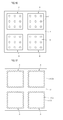
- FIG. 16 is a diagram showing a mask layer and protrusions.
- FIG. 17 is a diagram showing the same or another mask layer.
- FIG. 18 is a diagram showing one embodment of a light emitting device package that may include any of the aforementioned embodiments of the light emitting device.
- FIG. 19 is a diagram showing one embodiment of a backlight unit that may include any of the aforementioned embodiments of the light emitting device or package.
- FIG. 20 is a diagram showing one embodiment of a lighting unit that may include any of the aforementioned embodiments of the light emitting device or package.
- FIGS. 1 to 4 show one embodiment of a light emitting device and various stages of its manufacture.
- the light emitting device includes a light emitting structure layer 60 formed from a semiconductor layer 30 of a first conductivity type, an active layer 40 and a semiconductor layer 50 of a second conductivity type, all of which are suppored by a growth substrate 10.
- the LED further includes a first electrode 70 formed on the first conductivity type semiconductor layer 30, and a second electrode 80 formed on the second conductivity type semiconductor layer 50.
- a plurality of protrusions 11 are formed on the growth substrate 10.
- the protrusions 11 may be in a semi-spherical shape or another shape, and in terms of materials may be formed, for example, from one or more of SiO 2 , SiN, GaO, ZnO, or ITO.
- the protrusions 11 may serve to enhance the light extraction efficiency of the light emitting device by allowing light emitted from the active layer 40 to be scattered.
- the protrusions 11 may provided in various numbers and/or shapes in addition to those shown in FIG. 4 .
- the semiconductor layers on the growth substrate 10 include a first semiconductor layer, a second semiconductor layer, and the active layer between the first semiconductor layer and the second semiconductor layer.
- the first semiconductor layer is implemented by the first conductivity type semiconductor layer 30 and the second semiconductor layer is implemented by the second conductivity type semiconductor layer 50.
- the first conductivity type semiconductor layer 30 is formed with a stepped portion 31 at a lower edge surface thereof.
- the stepped portion 31 may be formed by extending the lower edge surfaces of the first conductivity type semiconductor layer 30. Some portions of the first conductivity type semiconductor layer 30 are spaced apart from the growth substrate 10. Also, in one embodiment, at least a portion of the stepped portion 31 and the protrusions 11 may be disposed on the same plane.
- the first conductivity type semiconductor layer 30 includes a first surface contacting the active layer 40 and a second surface oppositely facing the first surface.
- the area of the second surface may be smaller than a maximum area of the first conductivity type semiconductor layer due to the stepped portion 31.
- FIG. 4 One embodiment of a method for manufacturing the light emitting device shown in FIG. 4 will now be discussed with reference to FIGs. 1 to 4 .
- a growth substrate 10 is prepared and a plurality of protrusions 11 and a mask layer 12 are formed on the growth substrate 10.
- the growth substrate 10 may be formed, for example, of one or more of sapphire (A1 2 O 3 ), SiC, Si, GaAs, ZnO, MgO, GaN, Glass or Ga 2 O 3 .
- the mask layer 12 may be formed of the same material as that of the protrusions 11, e.g., SiO 2 , SiN, GaO, ZnO, or ITO.
- FIG. 16 shows an example of a plane view of mask layer 12 and protrusions 11.
- the mask layer 12 may be formed so that the growth substrate 10 is exposed so that the light emitting structure layer 60 may be grown. That is, a plurality of light emitting structure layer growth regions A may be defined by the mask layer 12.
- the light emitting structure layer 60 may not be grown on the mask layer 12, and in such a case the light emitting structure layer 60 on the light emitting structure layer growth regions A may be grown so that they are separated from each other by the mask layer 12.
- the protrusions may be partially formed on the light emitting structure layer growth regions A of the growth substrate 10 where the mask layer 12 is not formed.
- FIG. 17 shows another view of mask layer 12.
- the mask layer 12 formed on the growth substrate 10 and the light emitting structure layer growth regions A are defined by mask layer 12.
- the protrusions 11 are not formed on the growth substrate 10, but a protrusion pattern 12a may be formed on a side surface of the mask layer 12.
- This or another protrusion pattern corresponding to protrusion pattern 12a may be formed on a side surface of the first conductivity type semiconductor layer 30 grown on the light emitting structure layer growth regions A.
- a light emitting structure layer 60 including the first conductivity type semiconductor layer 30, an active layer 40 and a second conductivity type semiconductor layer 50, is grown on the growth substrate 10 on which the mask layer 12 and the protrusions 11 are formed.
- the first conductivity type semiconductor layer 30 is grown on the growth substrate 10 to cover the protrusions 11 through a horizontal growth and a vertical growth and to partially cover the mask layer 12.
- the mask layer 12 allows the light emitting structure layer 60 to be grown in multiple chip units on a substrate, for example, by dividing the growth substrate 10 into a plurality of light emitting structure layer growth regions A on which the light emitting structure 60 is grown. Thus, instead of scribing the substrate into individual chip units first (that is, right after formation of the light emitting structure layer), the light emitting structure layer is grown into multiple chip units on a single substrate.
- the crystallinity of a cleavage surface may not be good. As a result, leakage current may flow into the cleavage surface.
- the resulting light emitting structure layer 60 is grown into a high quality thin layer having improved properties in terms of crystallinity of the side surface.
- the first conductivity type semiconductor layer 30 may be grown, for example, as or into a GaN-based semiconductor layer including an n-type impurity such as silicon (Si), and the second conductivity type semiconductor layer 50 may be grown as or into a GaN-based semiconductor layer including a p-type impurity such as Mg.
- the active layer 40 may be formed of InGaN layer/GaN layer having a single quantum well structure or multi-quantum well structure by supplying ammonia (NH 3 ), trimethylgallium (TMGa), and trimethylindium (TMIn).
- NH 3 ammonia
- TMGa trimethylgallium
- TMIn trimethylindium
- a mesa etching step for partially removing the second conductivity type semiconductor layer 50, the active layer 40 and the first conductivity type semiconductor layer 30 is performed.
- mesa etching some of the first conductivity type semiconductor layer 30 is exposed in an upward direction.
- a first electrode 70 is formed on the first conductivity type semiconductor layer 30, and a second electrode 80 is formed on the second conductivity type semiconductor layer 50.
- the growth substrate 10 and the mask layer 12 are cut to divide the growth substrate 10 and the light emitting structure layer 60 into chip units.
- the growth substrate 10 may be cut by a scribing method or breaking method, and the mask layer 12 may be removed by an etching method.
- the mask layer 12 may be partially or completely removed.
- the stepped portion 31 is formed at a lower edge region of the first conductivity type semiconductor layer 30.
- a protrusion pattern may be formed on a side surface of the first conductivity type semiconductor layer.
- FIGS. 5 to 7 show a second embodiment of a light emitting device and various stages of its manufacture.
- the second embodiment of the light emitting device includes an undoped nitride layer 20 is formed on a growth substrate 10 and a light emitting structure layer 60 formed on the undoped nitride layer.
- the light emitting structure layer includes a first conductivity type semiconductor layer 30, an active layer 40, and a second conductivity type semiconductor layer 50.
- the LED includes a first electrode 70 formed on the first conductivity type semiconductor layer 30, and a second electrode 80 formed on the second conductivity type semiconductor layer 50.
- a plurality of protrusions 11 are formed on the growth substrate 10.
- the protrusions 11 may be in a semi-spherical shape or another shape, and may be formed, for example, of one or more of SiO 2 , SiN, GaO, ZnO, or ITO.
- the protrusions 11 may serve to enhance the light extraction efficiency of the light emitting device by allowing light emitted from the active layer 40 to be scattered.
- the protrusions 11 may be provided in various numbers and/or shapes in addition to those shown.
- the semiconductor layers on the growth substrate 10 include a first semiconductor layer, a second semiconductor layer, and the active layer between the first semiconductor layer and the second semiconductor layer.
- the first semiconductor layer includes the undoped nitride layer 20 and the first conductivity type semiconductor layer 30, and the second semiconductor layer is includes the second conductivity type semiconductor layer 50.
- the undoped nitride layer 20 is formed with a stepped portion 21 at one or more lower edge surfaces thereof. Some portions of the undoped nitride layer 20 may be spaced apart from the growth substrate 10. Also, at least a portion of the stepped portion 21 and the protrusions 11 may be disposed on the same plane.
- the undoped nitride layer 20 may include a first surface contacting the first conductivity type semiconductor layer 30 and a second surface oppositely facing the first surface, and the area of the second surface may be smaller than a maximum area of the first conductivity type semiconductor layer due to the stepped portion 21.
- a growth substrate 10 is prepared and a plurality of protrusions 11 and a mask layer 12 are formed on the growth substrate 10.
- the growth substrate 10 may be formed, for example, from one or more of of sapphire (A1 2 O 3 ), SiC, Si, GaAs, ZnO, MgO, GaN, Glass or Ga 2 O 3 .
- the mask layer 12 may be formed of the same material as the protrusions 11 and may be, for example, formed from one or more of SiO 2 , SiN, GaO, ZnO, or ITO.
- An undoped nitride layer 20 is grown on the growth substrate 10 on which the mask layer 12 and the protrusions 11 are formed.
- a light emitting structure layer 60 including a first conductivity type semiconductor layer 30, an active layer 40 and a second conductivity type semiconductor layer 50 is grown on the undoped nitride layer 20.
- the undoped nitride layer 20 is grown on the growth substrate 10 to cover the mask layer 12 and the protrusions 11 through a horizontal growth and a vertical growth.
- the undoped nitride layer 20 may not intentionally doped with a first conductivity type impurity, the undoped nitride layer 20 is a nitride layer which may have the first conductivity type conductivity, and may be, for example, formed of Un-GaN layer.
- the first conductivity type semiconductor layer 30 may be formed, for example, of a GaN-based semiconductor layer including an n-type impurity such as silicon (Si), and the second conductivity type semiconductor layer 50 may be formed of a GaN-based semiconductor layer including a p-type impurity such as Mg.
- the active layer 40 may be formed of InGaN layer/GaN layer having a single quantum well structure or multi-quantum well structure by supplying ammonia (NH 3 ), trimethylgallium (TMGa), and trimethylindium (TMIn).
- NH 3 ammonia
- TMGa trimethylgallium
- TMIn trimethylindium
- the result of a mesa etching technique is shown for partially removing the second conductivity type semiconductor layer 50, the active layer 40, and the first conductivity type semiconductor layer 30.
- mesa etching some of the first conductivity type semiconductor layer 30 is exposed in an upward direction.
- a first electrode 70 is formed on the first conductivity type semiconductor layer 30 and a second electrode 80 is formed on the second conductivity type semiconductor layer 50.
- the growth substrate 10 and the mask layer 12 are cut to divide the growth substrate 10 and the light emitting structure layer 60 into chip units.
- the growth substrate 10 may be cut by a scribing method or a breaking method, and the mask layer 12 may be removed by an etching method. At this time, the mask layer 12 may be completely or partially removed.
- the stepped portion 21 is formed at a lower edge region of the undoped nitride layer 20.
- a protrusion pattern may be formed on a side surface of the undoped nitride layer where the stepped portion 21 is formed.
- FIGS. 8 to 11 show a third embodiment of a light emitting device and various stages of its manufacture.
- the light emitting device includes a light emitting structure layer 60 formed from a first conductivity type semiconductor layer 30, an active layer 40, and a second conductivity type semiconductor layer 50.
- a first electrode 70 is formed on the first conductivity type semiconductor layer 30 and a second electrode 110 is formed under the second conductivity type semiconductor layer 50.
- the second electrode 110 includes an ohmic contact layer 111 under the second conductivity type semiconductor layer 50, a reflective layer 112 under the ohmic contact layer 111, and a conductivity supporting substrate 113 under the reflective layer 112.
- the semiconductor layers on the second electrode 110 include a first semiconductor layer, a second semiconductor layer, and the active layer between the first semiconductor layer and the second semiconductor layer.
- the first semiconductor layer is implemented by the first conductivity type semiconductor layer 30, and the second semiconductor layer is implemented by the second conductivity type semiconductor layer 50.
- the first conductivity type semiconductor layer 30 is formed with a stepped portion 31 at an upper side surface thereof and with upper grooves 32 at an upper surface thereof.
- the upper grooves 32 may act as photonic crystals which allow the light emitted from the active layer 40 to be effectively extracted to an outside.
- the first conductivity type semiconductor layer 30 includes a first surface contacting the active layer 40 and a second surface oppositely facing the first surface.
- the area of the second surface may be smaller than a maximum area of the first conductivity type semiconductor layer due to the stepped portion 31.
- a growth substrate 10 is prepared and a plurality of protrusions 11 and a mask layer 12 are formed on the growth substrate 10.
- the growth substrate 10 may be formed, for example, from one or more of sapphire (Al 2 O 3 ), SiC, Si, GaAs, ZnO, MgO, GaN, Glass or Ga 2 O 3
- mask layer 12 may be formed of the same material as protrusions 11, e.g., one or more of SiO 2 , SiN, GaO, ZnO, or ITO.
- a light emitting structure layer 60 including a first conductivity type semiconductor layer 30, an active layer 40, and a second conductivity type semiconductor layer 50, is grown on the growth substrate 10 on which the mask layer 12 and the protrusions 11 are formed.
- the first conductivity type semiconductor layer 30 is grown on the growth substrate 10 to cover the mask layer 12 and the protrusions 11 through a horizontal growth and a vertical growth.
- the first conductivity type semiconductor layer 30 may be formed, for example, from a GaN-based semiconductor layer including an n-type impurity such as silicon (Si), and the second conductivity type semiconductor layer 50 may be formed, for example, from a GaN-based semiconductor layer including a p-type impurity such as Mg.
- the active layer 40 may be formed of InGaN layer/GaN layer having a single quantum well structure or multi-quantum well structure by supplying ammonia (NH 3 ), trimethylgallium (TMGa), and trimethylindium (TMIn).
- NH 3 ammonia
- TMGa trimethylgallium
- TMIn trimethylindium
- a protective layer 90 is formed between the light emitting structure layer 60 and light emitting structure layer 60.
- the protective layer 90 may be formed of a material such as polyimide or SOG or another material.
- a second electrode 110 is formed on the light emitting structure layer 60 and the protective layer 90.
- the second electrode layer 110 may be formed by first forming an ohmic contact layer 111, forming a reflective layer 112 on the ohmic contact layer 111, and forming a conductivity supporting substrate 113 on the reflective layer 112.
- the conductivity supporting substrate 113 may be formed to include, for example, at least one of copper (Cu), titanium (Ti), molybdenum (Mo), chromium (Cr), nickel (Ni), aluminum (AI), platinum (Pt), gold (Au), tungsten (W), or conductivity semiconductor material.
- the reflective layer 112 may be formed from a metal including, for example, at least one of silver (Ag), aluminum (AI), copper (Cu), or nickel (Ni) having a high reflectivity.
- the ohmic contact layer 111 may be formed of a transparent conductivity oxide, such as indium tin oxide (ITO), aluminum-doped zinc oxide (AZO), indium zinc oxide (IZO), antimony tin oxide (ATO), or zinc indium tin oxide (ZITO).
- ITO indium tin oxide
- AZO aluminum-doped zinc oxide
- IZO indium zinc oxide
- ATO antimony tin oxide
- ZITO zinc indium tin oxide
- the growth substrate 10, mask layer 12, protective layer 90, and protrusions 11 are removed.
- the growth substrate 10 may be removed using, for example, a laser lift-off method or a chemical lift-off method. Since the mask layer 12 and the protrusions 11 are disposed between the growth substrate 10 and the light emitting structure layer 60, the growth substrate 10 can be easily separated from the light emitting structure layer 60. That is, because the mask layer 12 and the protrusions 11 are not strongly bonded to the light emitting structure layer 60, the more wide the area of the mask layer 12 and the protrusions 11, the easier the separation of the growth substrate 10.
- the protrusions 11 and the mask layer 12 can be easily separated, and the protective layer 90 can be removed by using an etchant.
- the protrusions 11 and the mask layer 12 are removed, upper grooves 32 and stepped portions 31 are formed in the first conductivity type semiconductor layer 30.
- a first electrode 70 is formed on the first conductivity type semiconductor layer 30 and then the second electrode 110 is separated.
- FIGS. 12 to 15 show a fourth embodiment of a light emitting device and various stages of its manufacture.
- the light emitting device includes a light emitting structure layer 60 formed from a first conductivity type semiconductor layer 30, an active layer 40, and a second conductivity type semiconductor layer 50 is formed, and an undoped nitride layer 20 is formed on the first conductivity type semiconductor layer 30.
- a first electrode 70 is formed on the first conductivity type semiconductor layer 30 exposed by selectively removing the undoped nitride layer 20, and a second electrode 80 is formed under the second conductivity type semiconductor layer 50.
- the semiconductor layers on the second electrode 110 include a first semiconductor layer, a second semiconductor layer, and the active layer between the first semiconductor layer and the second semiconductor layer.
- the first semiconductor layer is implemented by the undoped nitride layer 20 and the first conductivity type semiconductor layer 30, and the second semiconductor layer is implemented by the second conductivity type semiconductor layer 50.
- the undoped nitride layer 20 is formed with a stepped portion 21 at an upper side surface thereof and with upper grooves 22 at an upper surface thereof.
- the upper grooves 22 may act as photonic crystals, which allow the light emitted from the active layer 40 to be effectively extracted to an outside.
- the undoped layer may be formed from a material other than an nitride, and the same is true of the undoped layer in the third and other embodiments described herein.
- the undoped nitride layer 20 includes a first surface contacting the first conductivity type semiconductor layer 30 and a second surface oppositely facing the first surface.
- the area of the second surface may be smaller than a maximum area of the first conductivity type semiconductor layer due to the stepped portion 21.
- a growth substrate 10 is prepared and a plurality of protrusions 11 and a mask layer 12 are formed on the growth substrate 10.
- the growth substrate 10 may be formed, for example, from one or more of sapphire (Al 2 O 3 ), SiC, Si, GaAs, ZnO, MgO, GaN, Glass or Ga 2 O 3 .
- the mask layer 12 may be formed of the same material as that of the protrusions 11 and may be, for example, formed of one or more of SiO 2 , SiN, GaO, ZnO, or ITO.
- the undoped nitride layer 20 is grown on the growth substrate 10 on which the mask layer 12 and the protrusions 11 are formed.
- a light emitting structure layer 60 including a first conductivity type semiconductor layer 30, an active layer 40, and a second conductivity type semiconductor layer 50, is grown on the undoped nitride layer 20.
- the undoped nitride layer 20 is grown on the growth substrate 10 to cover the mask layer 12 and the protrusions 11 through a horizontal growth and a vertical growth.
- the first conductivity type semiconductor layer 30 may be formed, for example, from a GaN-based semiconductor layer including an n-type impurity such as silicon (Si), and the second conductivity type semiconductor layer 50 may be formed, for example, from a GaN-based semiconductor layer including a p-type impurity such as Mg.
- the active layer 40 may be formed of InGaN layer/GaN layer having a single quantum well structure or multi-quantum well structure by supplying ammonia (NH 3 ), trimethylgallium (TMGa), and trimethylindium (TMln).
- NH 3 ammonia
- TMGa trimethylgallium
- TMln trimethylindium
- a protective layer 90 may be formed between the light emitting structure layer 60 and the light emitting structure layer 60.
- the protective layer 90 may be formed of a material such as polyimide or SOG or another material.
- a second electrode 110 is formed on the light emitting structure layer 60 and the protective layer 90.
- the second electrode layer 110 may be formed by first forming an ohmic contact layer 111, forming a reflective layer 112 on the ohmic contact layer 111, and forming a conductivity supporting substrate 113 on the reflective layer 112.
- the conductivity supporting substrate 113 may be formed to include at least one of copper (Cu), titanium (Ti), molybdenum (Mo), chromium (Cr), nickel (Ni), aluminum (Al), platinum (Pt), gold (Au), tungsten (W), or conductivity semiconductor material.
- the reflective layer 112 may be formed to include a metal corresponding to at least one of silver (Ag), aluminum (Al), copper (Cu), or nickel (Ni) having a high reflectivity.
- the ohmic contact layer 111 may be formed of a transparent conductivity oxide, such as indium tin oxide (ITO), aluminum-doped zinc oxide (AZO), indium zinc oxide (IZO), antimony tin oxide (ATO), or zinc indium tin oxide (ZITO).
- ITO indium tin oxide
- AZO aluminum-doped zinc oxide
- IZO indium zinc oxide
- ATO antimony tin oxide
- ZITO zinc indium tin oxide
- the growth substrate 10, mask layer 12, protective layer 90, and protrusions 11 are removed.
- the growth substrate 10 may be removed using, for example, a laser lift-off method or a chemical lift-off method. Since the mask layer 12 and the protrusions 11 are disposed between the growth substrate 10 and the undoped nitride layer 20, the growth substrate 10 can be easily separated from the undoped nitride layer 20. That is, since the mask layer 12 and the protrusions 11 are not strongly bonded to the undoped nitride layer 20, the more wide the area of the mask layer 12 and the protrusions 11, the easier the separation of the growth substrate 10.
- the protrusions 11 and the mask layer 12 can be easily separated and the protective layer 90 can be removed by using an etchant. Accordingly upper grooves 32 and stepped portions 31 are formed in the undoped nitride layer 20.
- the undoped nitride layer 20 is selectively removed to expose the first conductivity type semiconductor layer 30, and a first electrode 70 is formed on the first conductivity type semiconductor layer 30.
- FIG. 18 shows a light emitting device package that includes any of the aforemtioned embodiments of the light emitting device.
- the light emitting device package 600 includes a package body 300, first and second conductivity layers 310 and 320 mounted on the package body 300, a light emitting device 200 mounted on the package body 300 and electrically coupled to the first and second conductivity layers 310 and 320, and a molding member 500 enclosing the light emitting device 200.
- the package body 300 may be formed to include, for example, one or more of a silicon material, a synthetic resin material, or a metallic material and may have an inclined surface around the light emitting device 200.
- the first conductivity layer 310 and the second conductivity layer 320 are electrically separated and supply electric power to the light emitting device 200. Also, the first and second conductivity layers 310 and 320 may reflect light generated from the light emitting device 200 to increase light efficiency and may emit heat generated from the light emitting device 200 to an outside or external location.
- the light emitting device 200 may be any of the light emitting devices previously described, and light emitting device 200 may be mounted on the package body 300 or on the first conductivity layer 310 or the second conductivity layer 320. The light emitting device 200 may be electrically coupled to the first conductivity layer 310 and the second conductivity layer 320 through a wire 400.
- the package of FIG. 18 is formed to include a light emitting device 200 according to the first or second embodiments, two wires 400 are used.
- the package is formed to include a light emitting device 200 according to the third or fourth embodiments, only one wire 400 may be used.
- the wire 400 may not be used at all.
- the molding member 500 may be provided to enclose and protect the light emitting device 100.
- a fluorescent material may be included in the molding member 500 to change the wavelength of light emitted from the light emitting device 200. Because the light emitting device package 600 employs a light emitting device 200 having enhanced light efficiency, it follows that light emitting device package 600 will also demonstrate superior light efficiency.
- the light emitting device package 600 may include a plurality of light emitting device packages arrayed onto a substrate.
- a plurality of optical members such as a light guide panel, a prism sheet, a diffusion sheet, a fluorescent sheet, and/or the like, may be arranged on a path of light emitted from the light emitting device package 600.
- the light emitting device package, substrate, and optical members may function as a backlight unit or lighting unit, and a lighting system may include, for example, a backlight unit, a lighting unit, an indicator unit, a lamp, a streetlamp, etc.
- FIG. 19 shows a disassembled view of a backlight unit 1100 that includes a light emitting device or package according to any one of the aforementioned embodiment.
- the backlight unit 1100 may serve as a lighting system for a variety of applications.
- the backlight unit 1100 may include a bottom frame 1140, a light guide member 1120 disposed in the bottom frame, and a light emitting module 1110 disposed on at least one side surface of light guide member 1120 and/or under light guide member 1120.
- a reflective sheet 1130 may be disposed under the light guide member 1120.
- the bottom frame 1140 may be formed in a box shape a top surface of which is opened such that the light guide member 1120, the light emitting module 1110 and the reflective sheet 1130 can be received.
- the bottom frame 1140 may be formed of a metal or resin material, but other materials are also possible.
- the light emitting module 1110 may include a substrate 700 and a plurality of light emitting device packages 600 mounted on the substrate 700.
- the plurality of light emitting device packages 600 may provide light to the light guide member 1120.
- the light emitting device packages 600 are mounted on substrate 700, but in other embodiments the light emitting devices may be mounted directly on the substrate 700.
- the light emitting module 1110 may be disposed on at least one of inner side surfaces of the bottom frame 1140, and thus may provide light to at least one of the side surfaces of the light guide member 1120.
- the light emitting module 1110 may be disposed under the light guide member 1120 inside the bottom frame 1140 to provide light toward a bottom surface of the light guide member 1120.
- the constitution may be modified according to the specific design requirements of the backlight unit 1100 according to, for example, an intended application.
- the light guide member 1120 may be disposed inside the bottom frame 1140.
- the light guide member 1120 may convert the light provided from the light emitting module to a planar light source and guide the converted plane light source to a display panel (not shown).
- the light guide member 1120 may be, for example, a light guide panel (LGP).
- LGP may be formed of, for example, one of acryl-series resin such as polymethyl metaacrylate (PMMA), polyethylene terephthlate (PET), poly carbonate (PC), COC, and polyethylene naphthalate resin.
- PMMA polymethyl metaacrylate
- PET polyethylene terephthlate
- PC poly carbonate
- COC polyethylene naphthalate resin
- An optical sheet 1150 may be disposed on the light guide member 1120, and may include, for example, at least one of a diffusion sheet, a light-condensing sheet, a brightness enhancement sheet and a fluorescent sheet.
- the optical sheet 1150 may be configured by the diffusion sheet, the light-condensing sheet, the brightness enhancement sheet and the fluorescent sheet stacked.
- the diffusion sheet 1150 diffuses the light emitted from the light emitting module 1110 uniformly, and the diffused light may be condensed on the display panel (not shown) by the light-condensing sheet.
- the light emitted from the light-condensing sheet is a randomly polarized light
- the brightness enhancement sheet may increase the polarization of the light emitted from the light-condensing sheet.
- the light-condensing sheet may be, for example, a horizontal and/or vertical prism sheet.
- the brightness enhancement sheet may be, for example, a dual brightness enhancement film.
- the fluorescent sheet may be a transparent plate or film including a fluorescent material.
- the reflective sheet 1130 may be disposed under the light guide member 1120, and may serve to reflect light emitted from the bottom surface of the light guide member 1120 toward a light emitting surface of the light guide member 1120.
- the reflective sheet 1130 may be formed, for example, of a resin material having good reflectivity such as PET, PC, or PVC resins or other materials.
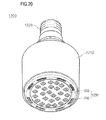
- FIG. 20 shows a lighting unit 1200 that includes any one or more of the aforementioned embodiments of the light emitting device or light emitting device package.
- This lighting unit includes a case body 1210, a light emitting module 1230 installed in the case body 1210, and a connection terminal 1220 installed in the case body 1210 to be supplied with an electric power from an external power source.
- the case body 1210 may be formed of a material having good heat shielding characteristic, for example, a metal material or a resin material.
- the light emitting module 1230 may include a substrate 700, and at least one light emitting device package 600 mounted on the substrate 700.
- the light emitting device packages 600 are mounted on the substrate 700, but the light emitting devices according to any of the embodiments described herein may be mounted directly on the substrate 700.
- the substrate 700 may be an insulator substrate on which a circuit pattern is printed and may include, for example, a general printed circuit board (PCB), a metal core PCB, a flexible PCB, a ceramic PCB, etc. Also, the substrate 700 may be formed of a material to efficiently reflect light, and a surface thereof may be formed in a color capable of efficiently reflecting light, for example, white color, silver color, or the like.
- PCB general printed circuit board
- At least one light emitting device package may be mounted on the substrate 700.
- Each of the light emitting device packages 200 may include at least one light emitting diode (LED).
- the light emitting diode may include a color LED emitting red, green, blue or white light, and a UV LED emitting ultraviolet (UV).
- the light emitting module 1230 may have a combination of several LEDs so as to obtain desired color and luminance.
- the light emitting module 1230 may have a combination of a white LED, a red LED, and a green LED so as to obtain a high color rendering index (CRI).
- a fluorescent sheet may be further disposed on a path of light emitted from the light emitting module 1230. The fluorescent sheet converts the wavelength of the light emitted from the light emitting module.
- the fluorescent sheet may include a yellow fluorescent material, so that the light, which is emitted from the light emitting module 1230 and passes through the fluorescent sheet, finally appears as white light.
- connection terminal 1220 may be electrically coupled to the light emitting module 1230 to supply an electric power to the light emitting module 1230. As shown in FIG. 19 , the connection terminal 1220 may be screwed and coupled to an external power, but the invention is not limited thereto. For example, the connection terminal 1220 may be made in a pin type and inserted into an external power, or may be connected to the external power through a power line.
- the lighting system may include at least one of a light guide member, a diffusion sheet, a light-condensing sheet, a brightness enhancement sheet and a fluorescent sheet on a traveling path of light to obtain a desired optical effect. Because the lighting system includes a light emitting device or package having superior light efficiency, the lighting system can show superior light efficiency as well.
- One or more embodiments described herein thus, provide a light emitting device having a novel structure and a method of manufacturing the same.
- One or more of these embodiments also provide a light emitting device with enhanced light efficiency, and a method of manufacturing the same.
- One or more of these embodiments also provide a light emitting device and a method of manufacturing the same in which a growth substrate can be easily separated.
- a light emitting device comprises: a first semiconductor layer; a second semiconductor layer; and an active layer between the first and second semiconductor layers, the first semiconductor layer includes a first surface facing the active layer, and a second surface oppositely facing the first surface, and the first semiconductor layer has a stepped portion formed at a side surface thereof and thus the area of the second surface is smaller than a maximum area of the first semiconductor layer.
- a light emitting device package comprises: a package body; a first conductivity layer and a second conductivity layer on the package body; a light emitting device disposed on the package body and electrically connected to the first conductivity layer and the second conductivity layer; and a molding member enclosing the light emitting device, wherein the light emitting device includes a first semiconductor layer, a second semiconductor layer, and an active layer between the first semiconductor layer and the second semiconductor layer, the first semiconductor layer includes a first surface facing the active layer, and a second surface oppositely facing the first surface, and the first semiconductor layer has a stepped portion formed at a side surface thereof and thus the area of the second surface is smaller than a maximum area of the first semiconductor layer.
- a lighting system comprises: a light emitting module including a substrate; and a light emitting device on the substrate, wherein the light emitting device comprises: a first semiconductor layer; a second semiconductor layer; and an active layer between the first semiconductor layer and the second semiconductor layer, the first semiconductor layer includes a first surface facing the active layer, and a second surface oppositely facing the first surface, and the first semiconductor layer has a stepped portion formed at a side surface thereof and thus the area of the second surface is smaller than a maximum area of the first semiconductor layer.
- a method of manufacturing a light emitting device comprises: forming a mask layer defining a plurality of light emitting structure layer growth regions on a growth substrate; forming a light emitting structure layer including a first conductivity type semiconductor layer, an active layer and a second conductivity type semiconductor layer from the light emitting structure layer growth regions; selectively removing the light emitting structure layer and forming a first electrode on the first conductivity type semiconductor layer and a second electrode on the second conductivity type semiconductor layer; and cutting the growth substrate and the mask layer to separate the growth substrate and the light emitting structure layer.
- a method of manufacturing a light emitting device comprises: forming a mask layer defining a plurality of light emitting structure layer growth regions on a growth substrate; forming a light emitting structure layer including a first conductivity type semiconductor layer, an active layer and a second conductivity type semiconductor layer from the light emitting structure layer growth regions; forming a protective layer between the light emitting structure layers; forming a second electrode on the light emitting structure layer and the protective layer; separating the growth substrate and removing the mask layer and the protective layer; forming a first electrode on the first conductivity type semiconductor layer; and cutting the second electrode to separate the second electrode and the light emitting structure layer.
- a light emitting device comprises a first semiconductor layer; a second semiconductor layer; and an active layer between the first and second semiconductor layers, wherein the first semiconductor layer includes a first surface facing the active layer, a second surface opposing the first surface, and a side surface that includes a stepped portion.
- the stepped portion causes the side surface to extend beyond one of the first surface or second surface.
- the area of the first surface may be greater than an area of the second surface, the area of the second surface may be less than the area of the first surface as a result of the stepped portion, or an area of the first surface may be less than an area of the second surface.
- the first semiconductor layer is a first conductivity type and the second semiconductor layer is a second conductivity type.
- the device may also include a buffer layer, wherein a first semiconductor layer is located between the buffer layer and active layer, the first semiconductor layer is of a first conductivity type, and the second semiconductor layer is of a second conductivity type.
- the buffer layer may be on a first portion of the first conductivity type semiconductor, and the device may further comprise a first electrode on the first semiconductor layer where the buffer layer is not formed and a second electrode under the second semiconductor layer.
- the buffer layer may be divided into first and second sections disposed on the first semiconductor layer, the first and second sections of the buffer layer separated to expose a portion of the first semiconductor layer, the first electrode electrically coupled to the exposed portion of the first semiconductor layer.
- the buffer layer may be an undoped layer or a doped layer, and if undoped may include a nitride.
- the device may further include at least one reflector to reflect light emitted from the active layer.
- the reflector is located adjacent the first semiconductor layer, and may be formed as a protrusion that extends from a surface of a substrate that supports or is coupled to the first semiconductor layer.
- the device may also include at least one diffuser, located on the second surface of the first semiconductor layer, to diffuse light emitted from the active layer.
- the diffuser may extend into the second surface of the first semiconductor layer, and may include a recess that extends into the second surface of the first semiconductor layer.
- a light emitting device comprises a buffer layer, a first semiconductor layer, a second semiconductor layer, and an active layer between the first and second semiconductor layers.
- the first semiconductor layer is between the buffer layer and active layer
- the active layer is between the first and second semiconductor layers
- a bottom surface of the buffer layer has an area smaller than an area of at least one of the surfaces of the first semiconductor layer
- a side surface of the buffer layer may includes a stepped portion which causes a top surface of the buffer layer facing the first semiconductor layer to have an area greater than the bottom surface of the buffer layer.
- a side surface of the buffer layer may includes a stepped portion which causes the side surface of the buffer layer to extend beyond at least one of a top surface or the bottom surface of the buffer layer.
- the buffer layer may be a doped layer or an undoped layer.
- the devoce may include at least one reflector to reflect light emitted from the active layer.
- the reflector may be adjacent the buffer layer and may include a protrusion that extends from a surface of a substrate that supports or is coupled to the buffer layer.
- a light emitting device package may be formed to comprise a light emitting device in accordance with any one of the aforementioned embodiments.
- a lighting system comprises a light emitting device as recited in claim 1, wherein said device is coupled to a substrate of a light emitting module.
- a method of manufacturing a light emitting device comprises forming a mask layer on a substrate to define a region of a light emitting device; forming a semiconductor layer of a first conductivity type, an active layer, and a semiconductor layer of a second conductivity type at said region; selectively removing the mask layer; and forming first and second electrodes electrically coupled to the first and second semiconductor layers respectively, wherein one of the semiconductor layers is formed to include a first surface facing the active layer, a second surface opposing the first surface, and a side surface that includes a stepped portion, and wherein the stepped portion causes the side surface to extend beyond one of the first surface or second surface.
- a method of manufacturing a light emitting device comprises forming a mask layer on a substrate to define a region of a light emitting device; forming a semiconductor layer of a first conductivity type, an active layer, and a semiconductor layer of a second conductivity type at said region;selectively removing the mask layer; and forming first and second electrodes electrically coupled to the first and second semiconductor layers respectively, wherein one of the semiconductor layers is formed to include a first surface facing the active layer.
- the method further includes forming a buffer layer coupled to the first and second semiconductor layers and the active layer, wherein a bottom surface of the buffer layer has an area smaller than an area of at least one of the surfaces of the semiconductor layer of the first conductivity type or the second conductivity type.
- buffer layer may include a stepped portion that causes the bottom surface of the buffer layer to have an area smaller than an area of at least one of the surfaces of the semiconductor layer of the first conductivity type or the second conductivity type.
- a layer or film
- it can be directly on the other layer or substrate, or that intervening layers may be present between them.
- intervening layers may be present between them.
- a layer is referred to as being "between” two layers, that layer may be the only one between the two layers or one or more intervening layers may also be present between them.
- any reference in this specification to "one embodiment,” “an embodiment,” “example embodiment,” etc. means that a particular feature, structure, or characteristic described in connection with the embodiment is included in at least one embodiment of the invention.
- the appearances of such phrases in various places in the specification are not necessarily all referring to the same embodiment.
Landscapes
- Led Devices (AREA)
Applications Claiming Priority (1)
| Application Number | Priority Date | Filing Date | Title |
|---|---|---|---|
| KR1020100010204A KR101658838B1 (ko) | 2010-02-04 | 2010-02-04 | 발광 소자 및 그 제조방법 |
Publications (2)
| Publication Number | Publication Date |
|---|---|
| EP2355175A2 true EP2355175A2 (fr) | 2011-08-10 |
| EP2355175A3 EP2355175A3 (fr) | 2014-04-30 |
Family
ID=43838005
Family Applications (1)
| Application Number | Title | Priority Date | Filing Date |
|---|---|---|---|
| EP10175066.9A Withdrawn EP2355175A3 (fr) | 2010-02-04 | 2010-09-02 | Appareil électroluminescent, son procédé de fabrication, paquet de dispositif électroluminescent et système d'éclairage |
Country Status (5)
| Country | Link |
|---|---|
| US (2) | US20110186889A1 (fr) |
| EP (1) | EP2355175A3 (fr) |
| KR (1) | KR101658838B1 (fr) |
| CN (1) | CN102148303B (fr) |
| TW (1) | TW201128802A (fr) |
Cited By (1)
| Publication number | Priority date | Publication date | Assignee | Title |
|---|---|---|---|---|
| EP2858130A1 (fr) * | 2013-10-04 | 2015-04-08 | LG Innotek Co., Ltd. | Dispositif électroluminescent |
Families Citing this family (12)
| Publication number | Priority date | Publication date | Assignee | Title |
|---|---|---|---|---|
| KR101259999B1 (ko) * | 2011-04-28 | 2013-05-06 | 서울옵토디바이스주식회사 | 반도체 기판 및 그 제조방법 |
| KR101259483B1 (ko) * | 2011-06-01 | 2013-05-06 | 서울옵토디바이스주식회사 | 반도체 발광 소자 및 그 제조 방법 |
| EP2888757A1 (fr) * | 2012-08-23 | 2015-07-01 | Sixpoint Materials Inc. | Substrat composite de nitrure de gallium et d'oxyde de métal |
| WO2014088322A1 (fr) * | 2012-12-04 | 2014-06-12 | 주식회사 세미콘라이트 | Diode électroluminescente à semi-conducteur, et procédé de fabrication de ladite diode électroluminescente à semi-conducteur |
| TWI597863B (zh) * | 2013-10-22 | 2017-09-01 | 晶元光電股份有限公司 | 發光元件及其製造方法 |
| JP6684541B2 (ja) * | 2014-01-20 | 2020-04-22 | ローム株式会社 | 発光素子 |
| CN105158831B (zh) * | 2015-10-23 | 2018-11-30 | 深圳市华星光电技术有限公司 | 一种柔性板 |
| KR102692637B1 (ko) * | 2016-11-24 | 2024-08-06 | 쑤저우 레킨 세미컨덕터 컴퍼니 리미티드 | 반도체 소자 및 이를 포함하는 반도체 소자 패키지 |
| KR102393071B1 (ko) * | 2017-03-27 | 2022-05-03 | 엘지전자 주식회사 | 반도체 발광 소자를 이용한 디스플레이 장치 |
| TWI870379B (zh) * | 2019-01-25 | 2025-01-21 | 晶元光電股份有限公司 | 發光元件及其製造方法 |
| KR102796432B1 (ko) * | 2020-01-30 | 2025-04-16 | 엘지전자 주식회사 | 반도체 발광소자를 이용한 디스플레이 장치 및 이의 제조방법 |
| CN115241338A (zh) * | 2022-08-01 | 2022-10-25 | 江苏第三代半导体研究院有限公司 | 一种氮化物半导体结构及其制备方法和应用 |
Citations (3)
| Publication number | Priority date | Publication date | Assignee | Title |
|---|---|---|---|---|
| US20050104081A1 (en) * | 2003-11-18 | 2005-05-19 | Kim Seong-Jin | Semiconductor light emitting diode and method for manufacturing the same |
| US20060225644A1 (en) * | 2005-04-07 | 2006-10-12 | Samsung Electro-Mechanics Co.,Ltd. | Vertical group III-nitride light emitting device and method for manufacturing the same |
| WO2009154215A1 (fr) * | 2008-06-20 | 2009-12-23 | 昭和電工株式会社 | Élément électroluminescent à semi-conducteurs de nitrure de groupe iii, procédé de fabrication dudit élément et lampe |
Family Cites Families (38)
| Publication number | Priority date | Publication date | Assignee | Title |
|---|---|---|---|---|
| US6274890B1 (en) * | 1997-01-15 | 2001-08-14 | Kabushiki Kaisha Toshiba | Semiconductor light emitting device and its manufacturing method |
| TW427039B (en) | 1997-06-16 | 2001-03-21 | Matsushita Electric Industrial Co Ltd | Manufacturing method for semiconductor, manufacturing method for semiconductor device, manufacturing method for semiconductor substrate |
| US6423984B1 (en) * | 1998-09-10 | 2002-07-23 | Toyoda Gosei Co., Ltd. | Light-emitting semiconductor device using gallium nitride compound semiconductor |
| DE10006738C2 (de) * | 2000-02-15 | 2002-01-17 | Osram Opto Semiconductors Gmbh | Lichtemittierendes Bauelement mit verbesserter Lichtauskopplung und Verfahren zu seiner Herstellung |
| US6657237B2 (en) | 2000-12-18 | 2003-12-02 | Samsung Electro-Mechanics Co., Ltd. | GaN based group III-V nitride semiconductor light-emitting diode and method for fabricating the same |
| US6791119B2 (en) * | 2001-02-01 | 2004-09-14 | Cree, Inc. | Light emitting diodes including modifications for light extraction |
| DE10112542B9 (de) * | 2001-03-15 | 2013-01-03 | Osram Opto Semiconductors Gmbh | Strahlungsemittierendes optisches Bauelement |
| EP1378949A4 (fr) * | 2001-03-21 | 2006-03-22 | Mitsubishi Cable Ind Ltd | Dispositif luminescent semiconducteur |
| JP3852000B2 (ja) * | 2001-09-28 | 2006-11-29 | 豊田合成株式会社 | 発光素子 |
| DE10148227B4 (de) * | 2001-09-28 | 2015-03-05 | Osram Opto Semiconductors Gmbh | Strahlungsemittierender Halbleiterchip, Verfahren zu dessen Herstellung und strahlungsemittierendes Bauelement |
| WO2003038957A1 (fr) * | 2001-10-29 | 2003-05-08 | Sharp Kabushiki Kaisha | Dispositif a semi-conducteur au nitrure, son procede de fabrication et appareil optique a semi-conducteur |
| KR100945984B1 (ko) | 2003-01-23 | 2010-03-09 | 엘지전자 주식회사 | 반도체 발광 다이오드 제조 방법 |
| EP1667241B1 (fr) * | 2003-08-19 | 2016-12-07 | Nichia Corporation | Diode électroluminescente semi-conductrice et son procédé de fabrication |
| KR100714639B1 (ko) | 2003-10-21 | 2007-05-07 | 삼성전기주식회사 | 발광 소자 |
| KR100497338B1 (ko) | 2003-12-30 | 2005-06-23 | 주식회사 이츠웰 | 발광 다이오드 및 그 제조 방법 |
| KR100530986B1 (ko) | 2003-11-18 | 2005-11-28 | 주식회사 이츠웰 | 발광 다이오드와 그 제조 방법 및 사파이어 기판의 식각방법 |
| JP2006086469A (ja) * | 2004-09-17 | 2006-03-30 | Matsushita Electric Ind Co Ltd | 半導体発光装置、照明モジュール、照明装置及び半導体発光装置の製造方法 |
| US8288942B2 (en) * | 2004-12-28 | 2012-10-16 | Cree, Inc. | High efficacy white LED |
| JP5016808B2 (ja) * | 2005-11-08 | 2012-09-05 | ローム株式会社 | 窒化物半導体発光素子及び窒化物半導体発光素子製造方法 |
| CN1964081A (zh) * | 2005-11-10 | 2007-05-16 | 中国科学院半导体研究所 | 氧化锌基的蓝光发光二极管及其制备方法 |
| JP2007173465A (ja) * | 2005-12-21 | 2007-07-05 | Rohm Co Ltd | 窒化物半導体発光素子の製造方法 |
| WO2007148866A1 (fr) | 2006-06-23 | 2007-12-27 | Lg Electronics Inc. | Diode électroluminescente ayant une topologie verticale et son procédé de fabrication |
| US20070295951A1 (en) | 2006-06-26 | 2007-12-27 | Jen-Inn Chyi | Light-emitting diode incorporating an array of light extracting spots |
| US20080042149A1 (en) * | 2006-08-21 | 2008-02-21 | Samsung Electro-Mechanics Co., Ltd. | Vertical nitride semiconductor light emitting diode and method of manufacturing the same |
| KR100867529B1 (ko) * | 2006-11-14 | 2008-11-10 | 삼성전기주식회사 | 수직형 발광 소자 |
| TWI354382B (en) * | 2007-06-01 | 2011-12-11 | Huga Optotech Inc | Semiconductor substrate with electromagnetic-wave- |
| KR20090002161A (ko) * | 2007-06-20 | 2009-01-09 | 엘지이노텍 주식회사 | 반도체 발광소자 및 반도체 발광소자의 제조 방법 |
| TW200908378A (en) | 2007-08-10 | 2009-02-16 | Tekcore Co Ltd | Manufacturing method of a light emitting diode |
| US20090085055A1 (en) | 2007-09-27 | 2009-04-02 | Hui Peng | Method for Growing an Epitaxial Layer |
| US8575633B2 (en) * | 2008-12-08 | 2013-11-05 | Cree, Inc. | Light emitting diode with improved light extraction |
| KR101382783B1 (ko) * | 2007-11-30 | 2014-04-08 | 엘지이노텍 주식회사 | 반도체 발광소자 및 그 제조방법 |
| KR20090073946A (ko) * | 2007-12-31 | 2009-07-03 | 주식회사 에피밸리 | 3족 질화물 반도체 발광소자 |
| KR101425167B1 (ko) * | 2008-01-07 | 2014-07-31 | 삼성전자주식회사 | 질화물 반도체 발광소자 제조방법 및 이에 의해 제조된질화물 반도체 발광소자 |
| KR101428066B1 (ko) | 2008-04-02 | 2014-08-07 | 엘지이노텍 주식회사 | 수직구조 그룹 3족 질화물계 반도체 발광다이오드 소자 및이의 제조 방법 |
| WO2009139376A1 (fr) * | 2008-05-14 | 2009-11-19 | 昭和電工株式会社 | Procédé de production d’un élément électroluminescent semi-conducteur en nitrure de groupe iii, élément électroluminescent semi-conducteur en nitrure de groupe iii et lampe |
| KR20100030472A (ko) * | 2008-09-10 | 2010-03-18 | 삼성전자주식회사 | 발광 소자 및 발광 장치의 제조 방법, 상기 방법을 이용하여 제조한 발광 소자 및 발광 장치 |
| KR101103882B1 (ko) * | 2008-11-17 | 2012-01-12 | 엘지이노텍 주식회사 | 반도체 발광소자 및 그 제조방법 |
| TWI487141B (zh) * | 2009-07-15 | 2015-06-01 | 榮創能源科技股份有限公司 | 提高光萃取效率之半導體光電結構及其製造方法 |
-
2010
- 2010-02-04 KR KR1020100010204A patent/KR101658838B1/ko not_active Expired - Fee Related
- 2010-09-02 EP EP10175066.9A patent/EP2355175A3/fr not_active Withdrawn
- 2010-09-16 CN CN201010289888.7A patent/CN102148303B/zh not_active Expired - Fee Related
- 2010-10-07 US US12/899,926 patent/US20110186889A1/en not_active Abandoned
- 2010-10-20 TW TW099135712A patent/TW201128802A/zh unknown
-
2014
- 2014-07-21 US US14/336,756 patent/US9484496B2/en not_active Expired - Fee Related
Patent Citations (3)
| Publication number | Priority date | Publication date | Assignee | Title |
|---|---|---|---|---|
| US20050104081A1 (en) * | 2003-11-18 | 2005-05-19 | Kim Seong-Jin | Semiconductor light emitting diode and method for manufacturing the same |
| US20060225644A1 (en) * | 2005-04-07 | 2006-10-12 | Samsung Electro-Mechanics Co.,Ltd. | Vertical group III-nitride light emitting device and method for manufacturing the same |
| WO2009154215A1 (fr) * | 2008-06-20 | 2009-12-23 | 昭和電工株式会社 | Élément électroluminescent à semi-conducteurs de nitrure de groupe iii, procédé de fabrication dudit élément et lampe |
Cited By (2)
| Publication number | Priority date | Publication date | Assignee | Title |
|---|---|---|---|---|
| EP2858130A1 (fr) * | 2013-10-04 | 2015-04-08 | LG Innotek Co., Ltd. | Dispositif électroluminescent |
| US9478703B2 (en) | 2013-10-04 | 2016-10-25 | Lg Innotek Co., Ltd. | Light emitting device |
Also Published As
| Publication number | Publication date |
|---|---|
| TW201128802A (en) | 2011-08-16 |
| KR101658838B1 (ko) | 2016-10-04 |
| KR20110090437A (ko) | 2011-08-10 |
| US9484496B2 (en) | 2016-11-01 |
| EP2355175A3 (fr) | 2014-04-30 |
| CN102148303B (zh) | 2015-05-06 |
| US20110186889A1 (en) | 2011-08-04 |
| US20140353580A1 (en) | 2014-12-04 |
| CN102148303A (zh) | 2011-08-10 |
Similar Documents
| Publication | Publication Date | Title |
|---|---|---|
| US9484496B2 (en) | Light emitting device, method of manufacturing the same, light emitting device package and lighting system | |
| US8319241B2 (en) | Light emitting device, light emitting device package, and lighting system | |
| US8748917B2 (en) | Light emitting device and method thereof | |
| CN102148322B (zh) | 发光器件和具有发光器件的发光器件封装 | |
| EP2362448B1 (fr) | Dispositif électroluminescent, son procédé de fabrication, conditionnement de dispositif électroluminescent et système d'éclairage | |
| KR101154709B1 (ko) | 발광 소자, 발광 소자 제조방법, 발광 소자 패키지 및 조명 시스템 | |
| CN102088018B (zh) | 发光器件和具有发光器件的发光器件封装 | |
| US8916891B2 (en) | Light emitting device, light emitting device package, method of manufacturing light emitting device, and lighting system | |
| EP2355196B1 (fr) | Boîtier de dispositif émetteur de lumière, son procédé de fabrication et système d'éclairage | |
| KR101916131B1 (ko) | 발광 소자, 발광 소자 제조방법 및 조명 시스템 | |
| US8878212B2 (en) | Light emitting device, method of manufacturing the light emitting device, light emitting device package, and lighting system | |
| US8368107B2 (en) | Light emitting device, method of manufacturing the same, and light emitting device package | |
| CN102117874B (zh) | 发光器件 | |
| KR101081169B1 (ko) | 발광 소자 및 그 제조방법, 발광 소자 패키지, 조명 시스템 | |
| US8513697B2 (en) | Light emitting device, method of manufacturing the same, light emitting device package, and illumination system | |
| KR20120130914A (ko) | 발광 소자 | |
| EP2381492B1 (fr) | Appareil électroluminescent avec une couche semi-conductrice ayant une epaisseur de résonance | |
| KR20110115384A (ko) | 발광 소자 및 그 제조방법, 발광 소자 패키지 및 조명 시스템 | |
| US20110089435A1 (en) | Light emitting device, method of manufacturing the same, light emitting device package, and lighting system | |
| KR20120014972A (ko) | 발광 소자, 발광 소자 제조방법, 발광 소자 패키지, 및 조명 시스템 | |
| KR20110118333A (ko) | 발광 소자, 발광 소자 제조방법, 발광 소자 패키지, 및 조명 시스템 | |
| KR20120000974A (ko) | 발광 소자, 발광 소자 제조방법, 발광 소자 패키지 및 조명 시스템 | |
| KR101664501B1 (ko) | 발광 소자, 발광 소자 제조방법, 발광 소자 패키지 및 조명 시스템 | |
| KR20120020599A (ko) | 발광 소자 및 발광 소자 패키지 | |
| KR20120029869A (ko) | 발광 소자 |
Legal Events
| Date | Code | Title | Description |
|---|---|---|---|
| PUAI | Public reference made under article 153(3) epc to a published international application that has entered the european phase |
Free format text: ORIGINAL CODE: 0009012 |
|
| 17P | Request for examination filed |
Effective date: 20100902 |
|
| AK | Designated contracting states |
Kind code of ref document: A2 Designated state(s): AL AT BE BG CH CY CZ DE DK EE ES FI FR GB GR HR HU IE IS IT LI LT LU LV MC MK MT NL NO PL PT RO SE SI SK SM TR |
|
| AX | Request for extension of the european patent |
Extension state: BA ME RS |
|
| PUAL | Search report despatched |
Free format text: ORIGINAL CODE: 0009013 |
|
| AK | Designated contracting states |
Kind code of ref document: A3 Designated state(s): AL AT BE BG CH CY CZ DE DK EE ES FI FR GB GR HR HU IE IS IT LI LT LU LV MC MK MT NL NO PL PT RO SE SI SK SM TR |
|
| AX | Request for extension of the european patent |
Extension state: BA ME RS |
|
| RIC1 | Information provided on ipc code assigned before grant |
Ipc: H01L 33/22 20100101ALN20140327BHEP Ipc: H01L 33/12 20100101ALN20140327BHEP Ipc: H01L 33/20 20100101ALI20140327BHEP Ipc: H01L 33/00 20100101AFI20140327BHEP |
|
| RAP1 | Party data changed (applicant data changed or rights of an application transferred) |
Owner name: LG INNOTEK CO., LTD. |
|
| RBV | Designated contracting states (corrected) |
Designated state(s): AL AT BE BG CH CY CZ DE DK EE ES FI FR GB GR HR HU IE IS IT LI LT LU LV MC MK MT NL NO PL PT RO SE SI SK SM TR |
|
| 17Q | First examination report despatched |
Effective date: 20150715 |
|
| STAA | Information on the status of an ep patent application or granted ep patent |
Free format text: STATUS: THE APPLICATION IS DEEMED TO BE WITHDRAWN |
|
| 18D | Application deemed to be withdrawn |
Effective date: 20160630 |