EP2355255A1 - Anschlussbuchse und damit ausgestatteter Steckverbinder - Google Patents
Anschlussbuchse und damit ausgestatteter Steckverbinder Download PDFInfo
- Publication number
- EP2355255A1 EP2355255A1 EP10016042A EP10016042A EP2355255A1 EP 2355255 A1 EP2355255 A1 EP 2355255A1 EP 10016042 A EP10016042 A EP 10016042A EP 10016042 A EP10016042 A EP 10016042A EP 2355255 A1 EP2355255 A1 EP 2355255A1
- Authority
- EP
- European Patent Office
- Prior art keywords
- terminal fitting
- locking
- locking lance
- main portion
- cavity
- Prior art date
- Legal status (The legal status is an assumption and is not a legal conclusion. Google has not performed a legal analysis and makes no representation as to the accuracy of the status listed.)
- Granted
Links
Images



Classifications
-
- H—ELECTRICITY
- H01—ELECTRIC ELEMENTS
- H01R—ELECTRICALLY-CONDUCTIVE CONNECTIONS; STRUCTURAL ASSOCIATIONS OF A PLURALITY OF MUTUALLY-INSULATED ELECTRICAL CONNECTING ELEMENTS; COUPLING DEVICES; CURRENT COLLECTORS
- H01R13/00—Details of coupling devices of the kinds covered by groups H01R12/70 or H01R24/00 - H01R33/00
- H01R13/02—Contact members
- H01R13/10—Sockets for co-operation with pins or blades
- H01R13/11—Resilient sockets
- H01R13/113—Resilient sockets co-operating with pins or blades having a rectangular transverse section
-
- H—ELECTRICITY
- H01—ELECTRIC ELEMENTS
- H01R—ELECTRICALLY-CONDUCTIVE CONNECTIONS; STRUCTURAL ASSOCIATIONS OF A PLURALITY OF MUTUALLY-INSULATED ELECTRICAL CONNECTING ELEMENTS; COUPLING DEVICES; CURRENT COLLECTORS
- H01R13/00—Details of coupling devices of the kinds covered by groups H01R12/70 or H01R24/00 - H01R33/00
- H01R13/40—Securing contact members in or to a base or case; Insulating of contact members
- H01R13/42—Securing in a demountable manner
- H01R13/422—Securing in resilient one-piece base or case, e.g. by friction; One-piece base or case formed with resilient locking means
- H01R13/4223—Securing in resilient one-piece base or case, e.g. by friction; One-piece base or case formed with resilient locking means comprising integral flexible contact retaining fingers
-
- H—ELECTRICITY
- H01—ELECTRIC ELEMENTS
- H01R—ELECTRICALLY-CONDUCTIVE CONNECTIONS; STRUCTURAL ASSOCIATIONS OF A PLURALITY OF MUTUALLY-INSULATED ELECTRICAL CONNECTING ELEMENTS; COUPLING DEVICES; CURRENT COLLECTORS
- H01R13/00—Details of coupling devices of the kinds covered by groups H01R12/70 or H01R24/00 - H01R33/00
- H01R13/40—Securing contact members in or to a base or case; Insulating of contact members
- H01R13/42—Securing in a demountable manner
- H01R13/436—Securing a plurality of contact members by one locking piece or operation
- H01R13/4364—Insertion of locking piece from the front
-
- H—ELECTRICITY
- H01—ELECTRIC ELEMENTS
- H01R—ELECTRICALLY-CONDUCTIVE CONNECTIONS; STRUCTURAL ASSOCIATIONS OF A PLURALITY OF MUTUALLY-INSULATED ELECTRICAL CONNECTING ELEMENTS; COUPLING DEVICES; CURRENT COLLECTORS
- H01R13/00—Details of coupling devices of the kinds covered by groups H01R12/70 or H01R24/00 - H01R33/00
- H01R13/40—Securing contact members in or to a base or case; Insulating of contact members
- H01R13/42—Securing in a demountable manner
- H01R13/436—Securing a plurality of contact members by one locking piece or operation
- H01R13/4361—Insertion of locking piece perpendicular to direction of contact insertion
-
- H—ELECTRICITY
- H01—ELECTRIC ELEMENTS
- H01R—ELECTRICALLY-CONDUCTIVE CONNECTIONS; STRUCTURAL ASSOCIATIONS OF A PLURALITY OF MUTUALLY-INSULATED ELECTRICAL CONNECTING ELEMENTS; COUPLING DEVICES; CURRENT COLLECTORS
- H01R43/00—Apparatus or processes specially adapted for manufacturing, assembling, maintaining, or repairing of line connectors or current collectors or for joining electric conductors
- H01R43/16—Apparatus or processes specially adapted for manufacturing, assembling, maintaining, or repairing of line connectors or current collectors or for joining electric conductors for manufacturing contact members, e.g. by punching and by bending
Definitions
- the present invention relates to a terminal fitting and to a connector provided therewith.
- Japanese Unexamined Patent Publication No. 2009-252558 discloses such a connector that terminal fittings are inserted into cavities in a housing and locked by locking lances in the form of cantilevers extending along inner walls of the cavities to be retained.
- a locking structure for the locking lance is composed of a locking hole formed in a main portion of the terminal fitting having a rectangular tube shape and a projection-like locking portion formed on an outer surface of the locking lance, and a locked state is attained by inserting the locking portion into the locking hole.
- the present invention was developed in view of the above situation and an object thereof is to prevent a locking lance from being pulled into a main body of a terminal fitting while being undesirably deformed.
- a terminal fitting comprising a main portion substantially in the form of a rectangular tube formed with a locking hole open in an outer surface to be engaged with a locking lance to retain the terminal fitting in a cavity formed in a housing of a connector, wherein at least one restricting portion to be brought into contact with the locking lance to prevent any further entering movement of the locking lance when the locking lance enters the main portion in an undesirable manner is formed in the main portion.
- the locking lance having entered the main portion while being undesirably deformed is prevented from entering any further upon coming into contact with the restricting portion, there is no likelihood that the locking lance is plastically deformed beyond its resiliency limit. Therefore, the locking lance can be prevented from being pulled into the main portion of the terminal fitting while being undesirably deformed.
- a terminal fitting comprising a main portion substantially in the form of a rectangular tube formed with a locking hole open in an outer surface, the terminal fitting being inserted into a cavity formed in a housing made of synthetic resin and retained by engaging the locking hole with a locking lance in the form of a cantilever extending along an inner wall of the cavity, wherein a restricting portion to be brought into contact with the locking lance to prevent any further entering movement of the locking lance when the locking lance enters the main portion in an undesirable manner is formed in the main portion.
- the restricting portion is formed by partially hammering a wall portion constituting or forming part of the main portion to project.
- the restricting portion Since the restricting portion is formed by hammering the wall portion to project, it is connected to the wall portion at a plurality of positions. Therefore, the restricting portion of the present invention has higher strength as compared with the one supported only at one end.
- a pair of restricting portions are provided while being spaced apart in a width direction intersecting with (preferably both) an inserting direction of the terminal fitting and/or a resiliently deforming direction of the locking lance.
- the pair of restricting portions are provided while being spaced apart in the width direction, the posture of the locking lance is stabilized when the locking lance comes into contact with the restricting portions. This can prevent an undesirable deformation of the locking lance.
- an area of the restricting portion facing the locking lance is formed by bending a wall portion constituting or forming part of the main portion.
- an area of a restricting portion facing a locking lance is a cutting surface of a wall portion constituting a main portion or an edge portion formed by cutting, the locking lance may be damaged when coming into contact with the restricting portion.
- the area of the restricting portion facing the locking lance is formed by bending the wall portion constituting the main portion, there is no likelihood that the locking lance is damaged when coming into contact with the restricting portion.
- the restricting portion is narrow and long in forward and backward directions as a whole and/or has a cross-sectional shape thereof cut along a plane perpendicular to forward and backward directions bent substantially in L-shape.
- the locking hole is formed over the entire width of a wall of the main portion while cutting also distal end edges of adjacent lateral walls.
- a connector comprising:
- an entire width of the locking lance is slightly smaller than that of the terminal fitting.
- a front holder is to be assembled into or onto or to a housing main body, preferably after the terminal fitting is properly inserted into the cavity, to define part of the cavity.
- an inner surface of the front holder is recessed to form at least one terminal insertion space substantially corresponding to the respective cavity, wherein with the front holder assembled with the housing main body, the terminal insertion space is fitted on or to the terminal fitting.
- the front holder comes into contact with the locking lance, to prevent the locking lance from being resiliently deformed toward a retracted position.
- a retainer assembled into the housing is engageable with the terminal fitting so as to retain it by this locking action.
- a connector of this embodiment is constructed by at least partly inserting one or more, particularly a plurality of terminal fittings 30 into a housing 10 made e.g. of synthetic resin.
- the housing 10 includes a housing main body 11 and particularly a front holder 20 constituting or forming part of front end portions of one or more cavities 12 by being assembled into or onto or to the housing main body 11.
- One or more, particularly a plurality of cavities 12 are formed to penetrate through the housing main body 11 substantially in forward and backward directions.
- the one or more terminal fittings 30 are to be individually at least partly inserted into the respective cavities 12 from an insertion side, particularly substantially from behind (from right in FIG. 1 ).
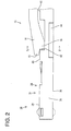
- a locking lance 13 particularly substantially in the form of a cantilever substantially extending forward is formed along a lateral or ceiling surface (upper inner wall in FIG. 1 ) in a part of each cavity 12 particularly slightly behind the front end thereof.
- the locking lance 13 is normally held or positioned at a locking position (see FIG. 1 ) where it can lock the terminal fitting 30 and resiliently deformable towards or to a retracted position (not shown) located above or more outward than (retracting direction from an insertion path for the terminal fitting 30 in the cavity 12) the locking position.
- Each locking lance 13 includes a lance main body 14 (particularly in the form of a plate substantially parallel to the ceiling or lateral wall) and a locking portion 15 projecting from the lateral or inner or lower surface (surface substantially facing the insertion path for the terminal fitting 30) of the lance main body 14.
- the locking portion 15 locks the terminal fitting 30 inserted up to a proper position in the cavity 12, thereby retaining the terminal fitting 30.
- the front end of the locking portion 15 is located slightly behind the front end of the lance main body 14, and an area (front end portion) of the lance main body 14 before the locking portion 15 serves as a jig contact portion 16.
- a jig (not shown) for resiliently deforming the locking lance 13 from the locking position toward the retracted position is or can be brought into contact with this jig contact portion 16 from inside or below.
- the entire width of the locking lance 13 including the lance main body 14 and the locking portion 15 particularly is slightly smaller than that of the terminal fitting 30.
- the lance main body 14 With the locking lance 13 located at the locking position, the lance main body 14 is located above the ceiling wall and the locking portion 15 is located below (or more inward than) the ceiling or lateral wall to at least partly enter the insertion path for the terminal fitting 30 to be locked.
- the locking portion 15 With the locking lance 13 located or positioned at the locking position, the locking portion 15 is located at a position retracted laterally or upward from the insertion path for the terminal fitting 30 to be locked.
- the front holder 20 is to be assembled into or onto or to the housing main body 11 particularly substantially from front after the one or more terminal fittings 30 are properly inserted into all the cavities 12.
- the rear surface of the front holder 20 is recessed to form one or more, particularly a plurality of terminal insertion spaces 21 substantially corresponding to the respective cavities 12.
- the front holder 20 assembled with the housing main body 11 the one or more respective terminal insertion spaces 21 are fitted on or to the front end portions of the one or more corresponding terminal fittings 30 (the front end portions of the respective terminal fittings 30 are at least partly accommodated in the corresponding terminal insertion spaces 21), wherefore the postures of the terminal fittings 30 in the cavities 12 are stabilized.
- the front holder 20 comes into contact with the upper or outer surfaces (surfaces vertically opposite to the locking portions 15) of the locking lances 13, thereby preventing the locking lances 13 from being resiliently deformed toward the retracted position.
- Each terminal fitting 30 particularly is a female terminal narrow and long in forward and backward directions (directions substantially parallel to a connecting direction with an unillustrated mating male terminal) as a whole.
- a front end part of the terminal fitting 30 is a main portion 31 (particularly substantially in the form of a rectangular or polygonal tube) having a resilient contact piece 32 accommodated therein, and a rear end part thereof is a wire connecting portion 34 (particularly in the form of at least one open barrel) to be connected to a wire 33 particularly by being crimped and connected to the wire 33.
- the main portion 31 particularly is formed into a rectangular or polygonal tube composed of a plurality of connected wall portions bent along folding lines substantially extending in forward and backward directions.
- the plurality of wall portions particularly include a bottom wall 35, lateral (left and right) walls 36, 37 projecting from or standing up (connected) at an angle different from 0° or 180°, preferably substantially at right angles from the (particularly substantially opposite) lateral (left and/or right) edges of the bottom wall 35, and an upper wall 38 particularly divided into three front, middle and rear parts.
- the upper wall 38 is composed of a front wall 39 extending at an angle different from 0° or 180°, preferably substantially at a right angle from a front end portion of the upper or outer end edge (extending end edge) of the left wall 36, a middle or intermediate wall 40 extending at an angle different from 0° or 180°, preferably substantially at a right angle from a position of the upper end edge of the left wall 36 behind the front wall 39, and a rear wall 41 extending at an angle different from 0° or 180°, preferably substantially at a right angle from a rear end portion of the left wall 36.
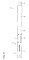
- a part between the middle or intermediate wall 40 and the rear wall 41 in an outer surface (upper surface) of the main portion 31 serves as a locking hole or recess 42 exposed to the outside of the main portion 31.
- the locking hole 42 particularly is formed over the entire width of the upper surface of the main portion 31 while cutting also the upper end edges of the lateral (right and left) walls 37, 36.
- the rear edge of the rear wall 41 of the main portion 31 serves as a locking edge portion 43 facing an upward or outward opening of a coupling portion.
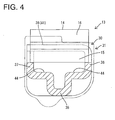
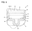
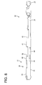
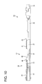
- the locking lance 13 may be deformed in such an undesirable manner that the lance main body 14 at least partly enters the main portion 31.
- at least either one or both of the opposite outer lateral walls of the locking lance 13 may be slightly scraped by edge portion(s) of the upper end edge(s) of either one or both of the opposite side walls of the terminal fitting 30. Since the jig contact portion 16 is caught by the rear end edge of the middle wall 40, the locking lance 13 is deformed to be curved as a whole. If a degree of this curved deformation exceeds resiliency limit of the locking lance 13, the locking lance 13 is plastically deformed or destroyed and cannot be reused.
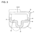
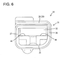
- the terminal fitting 30 is formed with one or more, particularly a pair of lateral (left and/or right) restricting portions 44 particularly spaced apart in a width direction (direction intersecting with both an inserting direction of the terminal fitting 30 and/or a resiliently deforming direction of the locking lance 13) as a means for preventing not only the locking portion 15, but also the lance main body 14 from being excessively deformed in an undesirable manner to enter the main portion 31 in a state where the locking lance 13 is located at the locking position.
- the restricting portions 44 particularly are formed by bending (i.e. partially hammering) at least one lateral portion (particularly substantially opposite lateral (left and right) edge portions) of the bottom wall 35 and/or one or more lower edge portions of the lateral (left and/or right) walls 36, 37 at an angle different from 0° or 180°, preferably substantially at right angles to project into the main portion 31.
- the restricting portions 44 particularly are narrow and long in forward and backward directions as a whole and cross-sectional shapes (shapes when viewed from front) thereof cut along a plane perpendicular to forward and backward directions are bent substantially in L-shape (substantially right angled).
- the lateral (upper) surface of the main portion 31 interferes with the locking portion 15, whereby the locking lance 13 is resiliently deformed in a direction intersecting with the insertion direction or outward (upward) from the locking position toward the retracted position.
- the terminal fitting 30 substantially reaches a proper insertion position, the locking lance 13 resiliently at least partly returns to the locking position, the locking portion 15 is engaged with the locking hole 42, and the terminal fitting 30 is held retained by this locking action.
- the restricting portions 44 particularly are formed by partially hammering the bottom wall 35 and/or the (particularly substantially opposite) lateral (left and/or right) walls 36, 37 constituting or forming part of the main portion 31, they are connected to the bottom wall 35 and/or the lateral (left and/or right) wall(s) 36, 37 particularly at a plurality of positions. Therefore, the restricting portions 44 of this embodiment have higher strength as compared with those supported only at one ends.
- the pair of restricting portions 44 particularly are provided while being spaced apart in the width direction intersecting with (particularly both) the inserting direction of the terminal fitting 30 and/or the resiliently deforming direction of the locking lance 13, the posture of the locking lance 13 is stabilized when the locking lance 13 comes into contact with the restricting portions 44, whereby it is possible to prevent inclination of the locking lance 13 to left and right and prevent an undesirable deformation of the locking lance 13 resulting from the inclination to left and right.
- areas of restricting portions facing a locking lance are cut surfaces of wall portions constituting a main portion or edge portions formed by cutting, the locking lance may be damaged when coming into contact with the restricting portions.
- areas (upper surfaces) of the restricting portions 44 facing the locking lance 13 are formed particularly by bending the bottom wall 35 and/or the lateral (left and/or right) wall(s) 36, 37 constituting the main portion 31, wherefore there is no likelihood of damaging the locking lance 13 even if the locking lance 13 comes into contact with the restricting portions 44.
- a terminal fitting 30 includes a main portion 31 (particularly substantially in the form of a rectangular or polygonal tube) formed with a locking hole or recess 42 open in an outer surface.
- the terminal fitting 30 is to be at least partly inserted into a cavity 12 formed in a housing 10 made e.g. of synthetic resin and retained by engaging the locking hole 42 with a locking lance 13, particularly substantially in the form of a cantilever extending along an inner wall of the cavity 12.
- One or more restricting portions 44 to be brought into contact with the locking lance 13 to prevent any further entering movement of the locking lance 13 when the locking lance 13 at least partly enters the main portion 31 in an undesirable manner is formed in the main portion 31.
Landscapes
- Connector Housings Or Holding Contact Members (AREA)
- Quick-Acting Or Multi-Walled Pipe Joints (AREA)
Applications Claiming Priority (1)
| Application Number | Priority Date | Filing Date | Title |
|---|---|---|---|
| JP2010021593A JP5446948B2 (ja) | 2010-02-02 | 2010-02-02 | 端子金具 |
Publications (2)
| Publication Number | Publication Date |
|---|---|
| EP2355255A1 true EP2355255A1 (de) | 2011-08-10 |
| EP2355255B1 EP2355255B1 (de) | 2014-08-20 |
Family
ID=43513966
Family Applications (1)
| Application Number | Title | Priority Date | Filing Date |
|---|---|---|---|
| EP10016042.3A Not-in-force EP2355255B1 (de) | 2010-02-02 | 2010-12-23 | Anschlussbuchse und damit ausgestatteter Steckverbinder |
Country Status (4)
| Country | Link |
|---|---|
| US (1) | US8226436B2 (de) |
| EP (1) | EP2355255B1 (de) |
| JP (1) | JP5446948B2 (de) |
| CN (1) | CN102170067B (de) |
Families Citing this family (13)
| Publication number | Priority date | Publication date | Assignee | Title |
|---|---|---|---|---|
| JP5629530B2 (ja) * | 2010-08-23 | 2014-11-19 | 矢崎総業株式会社 | コネクタ |
| WO2013135849A1 (en) * | 2012-03-16 | 2013-09-19 | Delphi Connection Systems Holding France | Electrical connector |
| JP5757426B2 (ja) * | 2012-03-28 | 2015-07-29 | 住友電装株式会社 | コネクタ |
| DE102013013632A1 (de) * | 2012-09-26 | 2014-04-10 | Lear Corp. | Elektrischer Anschluss |
| JP6211563B2 (ja) * | 2015-07-31 | 2017-10-11 | 矢崎総業株式会社 | 端子金具 |
| JP6760147B2 (ja) * | 2017-03-10 | 2020-09-23 | 株式会社オートネットワーク技術研究所 | シールド端子及びシールドコネクタ |
| JP2019050169A (ja) * | 2017-09-12 | 2019-03-28 | 住友電装株式会社 | コネクタ |
| JP6868596B2 (ja) * | 2018-08-28 | 2021-05-12 | 矢崎総業株式会社 | 防水コネクタ構造および防水コネクタ構造のコネクタ嵌合方法 |
| CN209282467U (zh) * | 2018-11-30 | 2019-08-20 | 泰科电子(上海)有限公司 | 端子保持架、连接器壳体、连接器、及连接器组件 |
| JP7146717B2 (ja) * | 2019-10-01 | 2022-10-04 | 矢崎総業株式会社 | コネクタ |
| DE102021100806A1 (de) | 2021-01-15 | 2022-07-21 | Te Connectivity Germany Gmbh | Kontakteinrichtung und Verfahren zur Herstellung der Kontakteinrichtung |
| JP7480716B2 (ja) * | 2021-01-21 | 2024-05-10 | 住友電装株式会社 | コネクタ |
| JP7622617B2 (ja) * | 2021-11-26 | 2025-01-28 | 住友電装株式会社 | コネクタ |
Citations (7)
| Publication number | Priority date | Publication date | Assignee | Title |
|---|---|---|---|---|
| US5630733A (en) * | 1994-02-16 | 1997-05-20 | Yazaki Corporation | Female terminal |
| US6179671B1 (en) * | 1998-06-08 | 2001-01-30 | Yazaki Corporation | Electric connector with terminal locking member |
| US20030008557A1 (en) * | 2001-07-04 | 2003-01-09 | Yazaki Corporation | Holder-equipped connector |
| EP1303008A2 (de) * | 2001-10-12 | 2003-04-16 | Delphi Technologies, Inc. | Verbinderteil eines elektrischen Steckverbinders |
| EP1635426A1 (de) * | 2003-06-18 | 2006-03-15 | Ryosei Electro-Circuit Systems, Ltd. | Verbindungsanschluss |
| JP2009252558A (ja) | 2008-04-07 | 2009-10-29 | Sumitomo Wiring Syst Ltd | コネクタ |
| EP2180553A2 (de) * | 2008-10-27 | 2010-04-28 | Hirose Electric Co., Ltd. | Elektrischer Anschluss und Endgerät für elektrischen Anschluss |
Family Cites Families (5)
| Publication number | Priority date | Publication date | Assignee | Title |
|---|---|---|---|---|
| JPS61133979U (de) * | 1985-02-12 | 1986-08-21 | ||
| JPH01158671U (de) * | 1988-04-22 | 1989-11-01 | ||
| JP3912204B2 (ja) * | 2002-06-28 | 2007-05-09 | 住友電装株式会社 | コネクタ |
| JP3763574B2 (ja) * | 2003-03-14 | 2006-04-05 | 日本航空電子工業株式会社 | コネクタ |
| JP2007250530A (ja) * | 2006-02-17 | 2007-09-27 | Auto Network Gijutsu Kenkyusho:Kk | 端子付電線 |
-
2010
- 2010-02-02 JP JP2010021593A patent/JP5446948B2/ja not_active Expired - Fee Related
- 2010-12-23 EP EP10016042.3A patent/EP2355255B1/de not_active Not-in-force
-
2011
- 2011-01-25 CN CN201110030748.2A patent/CN102170067B/zh not_active Expired - Fee Related
- 2011-01-31 US US13/017,073 patent/US8226436B2/en not_active Expired - Fee Related
Patent Citations (7)
| Publication number | Priority date | Publication date | Assignee | Title |
|---|---|---|---|---|
| US5630733A (en) * | 1994-02-16 | 1997-05-20 | Yazaki Corporation | Female terminal |
| US6179671B1 (en) * | 1998-06-08 | 2001-01-30 | Yazaki Corporation | Electric connector with terminal locking member |
| US20030008557A1 (en) * | 2001-07-04 | 2003-01-09 | Yazaki Corporation | Holder-equipped connector |
| EP1303008A2 (de) * | 2001-10-12 | 2003-04-16 | Delphi Technologies, Inc. | Verbinderteil eines elektrischen Steckverbinders |
| EP1635426A1 (de) * | 2003-06-18 | 2006-03-15 | Ryosei Electro-Circuit Systems, Ltd. | Verbindungsanschluss |
| JP2009252558A (ja) | 2008-04-07 | 2009-10-29 | Sumitomo Wiring Syst Ltd | コネクタ |
| EP2180553A2 (de) * | 2008-10-27 | 2010-04-28 | Hirose Electric Co., Ltd. | Elektrischer Anschluss und Endgerät für elektrischen Anschluss |
Also Published As
| Publication number | Publication date |
|---|---|
| JP2011159547A (ja) | 2011-08-18 |
| US20110189899A1 (en) | 2011-08-04 |
| EP2355255B1 (de) | 2014-08-20 |
| CN102170067A (zh) | 2011-08-31 |
| JP5446948B2 (ja) | 2014-03-19 |
| US8226436B2 (en) | 2012-07-24 |
| CN102170067B (zh) | 2014-03-05 |
Similar Documents
| Publication | Publication Date | Title |
|---|---|---|
| EP2355255B1 (de) | Anschlussbuchse und damit ausgestatteter Steckverbinder | |
| EP2530787B1 (de) | Steckverbinder und Montageverfahren dafür | |
| US8602819B2 (en) | Connector | |
| EP2058905B1 (de) | Steckverbinder | |
| US8708739B2 (en) | Connector | |
| US7445524B2 (en) | Connector | |
| JP2008153074A (ja) | 端子金具及びコネクタ | |
| EP3220490A1 (de) | Verbinderpositionbestätigungsvorrichtung, verbindergehäuse und elektrisches verbindersystem | |
| US20110250805A1 (en) | Terminal fitting | |
| EP2530788A1 (de) | Verbinder | |
| JP2018125167A (ja) | リテーナ付きコネクタ | |
| US20170352974A1 (en) | Connector | |
| EP1378968B1 (de) | Verbinder | |
| EP1376769B1 (de) | Verbinder mit elastischem Verriegelungselement | |
| JPH09330757A (ja) | コネクタ | |
| US20030190842A1 (en) | Terminal fitting and a connector provided therewith | |
| EP1294056A2 (de) | Anschlusskontakt, damit ausgestatteter Steckverbinder und Herstellungsverfahren des Anschlusskontaktes | |
| US6817901B2 (en) | Connector | |
| KR101752009B1 (ko) | 커넥터 | |
| US8241078B2 (en) | Male terminal fitting with a reduced space portion | |
| EP1560297B1 (de) | Verbinder mit gegen übermässige Deformation geschützter Halterung | |
| EP1391970B1 (de) | Verbinder | |
| JP4321417B2 (ja) | 端子金具及びコネクタ | |
| JP4457987B2 (ja) | コネクタ | |
| US7001224B2 (en) | Connector with retainer for locking terminal fitings |
Legal Events
| Date | Code | Title | Description |
|---|---|---|---|
| PUAI | Public reference made under article 153(3) epc to a published international application that has entered the european phase |
Free format text: ORIGINAL CODE: 0009012 |
|
| AK | Designated contracting states |
Kind code of ref document: A1 Designated state(s): AL AT BE BG CH CY CZ DE DK EE ES FI FR GB GR HR HU IE IS IT LI LT LU LV MC MK MT NL NO PL PT RO RS SE SI SK SM TR |
|
| AX | Request for extension of the european patent |
Extension state: BA ME |
|
| 17P | Request for examination filed |
Effective date: 20110825 |
|
| GRAP | Despatch of communication of intention to grant a patent |
Free format text: ORIGINAL CODE: EPIDOSNIGR1 |
|
| RIC1 | Information provided on ipc code assigned before grant |
Ipc: H01R 13/11 20060101AFI20140318BHEP Ipc: H01R 13/422 20060101ALI20140318BHEP |
|
| INTG | Intention to grant announced |
Effective date: 20140422 |
|
| RAP1 | Party data changed (applicant data changed or rights of an application transferred) |
Owner name: SUMITOMO WIRING SYSTEMS, LTD. |
|
| GRAS | Grant fee paid |
Free format text: ORIGINAL CODE: EPIDOSNIGR3 |
|
| GRAA | (expected) grant |
Free format text: ORIGINAL CODE: 0009210 |
|
| AK | Designated contracting states |
Kind code of ref document: B1 Designated state(s): AL AT BE BG CH CY CZ DE DK EE ES FI FR GB GR HR HU IE IS IT LI LT LU LV MC MK MT NL NO PL PT RO RS SE SI SK SM TR |
|
| REG | Reference to a national code |
Ref country code: GB Ref legal event code: FG4D |
|
| REG | Reference to a national code |
Ref country code: CH Ref legal event code: EP |
|
| REG | Reference to a national code |
Ref country code: AT Ref legal event code: REF Ref document number: 683897 Country of ref document: AT Kind code of ref document: T Effective date: 20140915 |
|
| REG | Reference to a national code |
Ref country code: IE Ref legal event code: FG4D |
|
| REG | Reference to a national code |
Ref country code: DE Ref legal event code: R096 Ref document number: 602010018331 Country of ref document: DE Effective date: 20141002 |
|
| REG | Reference to a national code |
Ref country code: AT Ref legal event code: MK05 Ref document number: 683897 Country of ref document: AT Kind code of ref document: T Effective date: 20140820 |
|
| REG | Reference to a national code |
Ref country code: NL Ref legal event code: VDEP Effective date: 20140820 |
|
| REG | Reference to a national code |
Ref country code: LT Ref legal event code: MG4D |
|
| PG25 | Lapsed in a contracting state [announced via postgrant information from national office to epo] |
Ref country code: FI Free format text: LAPSE BECAUSE OF FAILURE TO SUBMIT A TRANSLATION OF THE DESCRIPTION OR TO PAY THE FEE WITHIN THE PRESCRIBED TIME-LIMIT Effective date: 20140820 Ref country code: PT Free format text: LAPSE BECAUSE OF FAILURE TO SUBMIT A TRANSLATION OF THE DESCRIPTION OR TO PAY THE FEE WITHIN THE PRESCRIBED TIME-LIMIT Effective date: 20141222 Ref country code: SE Free format text: LAPSE BECAUSE OF FAILURE TO SUBMIT A TRANSLATION OF THE DESCRIPTION OR TO PAY THE FEE WITHIN THE PRESCRIBED TIME-LIMIT Effective date: 20140820 Ref country code: LT Free format text: LAPSE BECAUSE OF FAILURE TO SUBMIT A TRANSLATION OF THE DESCRIPTION OR TO PAY THE FEE WITHIN THE PRESCRIBED TIME-LIMIT Effective date: 20140820 Ref country code: NO Free format text: LAPSE BECAUSE OF FAILURE TO SUBMIT A TRANSLATION OF THE DESCRIPTION OR TO PAY THE FEE WITHIN THE PRESCRIBED TIME-LIMIT Effective date: 20141120 Ref country code: BG Free format text: LAPSE BECAUSE OF FAILURE TO SUBMIT A TRANSLATION OF THE DESCRIPTION OR TO PAY THE FEE WITHIN THE PRESCRIBED TIME-LIMIT Effective date: 20141120 Ref country code: ES Free format text: LAPSE BECAUSE OF FAILURE TO SUBMIT A TRANSLATION OF THE DESCRIPTION OR TO PAY THE FEE WITHIN THE PRESCRIBED TIME-LIMIT Effective date: 20140820 Ref country code: GR Free format text: LAPSE BECAUSE OF FAILURE TO SUBMIT A TRANSLATION OF THE DESCRIPTION OR TO PAY THE FEE WITHIN THE PRESCRIBED TIME-LIMIT Effective date: 20141121 |
|
| PG25 | Lapsed in a contracting state [announced via postgrant information from national office to epo] |
Ref country code: RS Free format text: LAPSE BECAUSE OF FAILURE TO SUBMIT A TRANSLATION OF THE DESCRIPTION OR TO PAY THE FEE WITHIN THE PRESCRIBED TIME-LIMIT Effective date: 20140820 Ref country code: IS Free format text: LAPSE BECAUSE OF FAILURE TO SUBMIT A TRANSLATION OF THE DESCRIPTION OR TO PAY THE FEE WITHIN THE PRESCRIBED TIME-LIMIT Effective date: 20141220 Ref country code: HR Free format text: LAPSE BECAUSE OF FAILURE TO SUBMIT A TRANSLATION OF THE DESCRIPTION OR TO PAY THE FEE WITHIN THE PRESCRIBED TIME-LIMIT Effective date: 20140820 Ref country code: LV Free format text: LAPSE BECAUSE OF FAILURE TO SUBMIT A TRANSLATION OF THE DESCRIPTION OR TO PAY THE FEE WITHIN THE PRESCRIBED TIME-LIMIT Effective date: 20140820 Ref country code: AT Free format text: LAPSE BECAUSE OF FAILURE TO SUBMIT A TRANSLATION OF THE DESCRIPTION OR TO PAY THE FEE WITHIN THE PRESCRIBED TIME-LIMIT Effective date: 20140820 |
|
| PG25 | Lapsed in a contracting state [announced via postgrant information from national office to epo] |
Ref country code: NL Free format text: LAPSE BECAUSE OF FAILURE TO SUBMIT A TRANSLATION OF THE DESCRIPTION OR TO PAY THE FEE WITHIN THE PRESCRIBED TIME-LIMIT Effective date: 20140820 |
|
| PG25 | Lapsed in a contracting state [announced via postgrant information from national office to epo] |
Ref country code: DK Free format text: LAPSE BECAUSE OF FAILURE TO SUBMIT A TRANSLATION OF THE DESCRIPTION OR TO PAY THE FEE WITHIN THE PRESCRIBED TIME-LIMIT Effective date: 20140820 Ref country code: EE Free format text: LAPSE BECAUSE OF FAILURE TO SUBMIT A TRANSLATION OF THE DESCRIPTION OR TO PAY THE FEE WITHIN THE PRESCRIBED TIME-LIMIT Effective date: 20140820 Ref country code: IT Free format text: LAPSE BECAUSE OF FAILURE TO SUBMIT A TRANSLATION OF THE DESCRIPTION OR TO PAY THE FEE WITHIN THE PRESCRIBED TIME-LIMIT Effective date: 20140820 Ref country code: RO Free format text: LAPSE BECAUSE OF FAILURE TO SUBMIT A TRANSLATION OF THE DESCRIPTION OR TO PAY THE FEE WITHIN THE PRESCRIBED TIME-LIMIT Effective date: 20140820 Ref country code: SK Free format text: LAPSE BECAUSE OF FAILURE TO SUBMIT A TRANSLATION OF THE DESCRIPTION OR TO PAY THE FEE WITHIN THE PRESCRIBED TIME-LIMIT Effective date: 20140820 Ref country code: CZ Free format text: LAPSE BECAUSE OF FAILURE TO SUBMIT A TRANSLATION OF THE DESCRIPTION OR TO PAY THE FEE WITHIN THE PRESCRIBED TIME-LIMIT Effective date: 20140820 |
|
| REG | Reference to a national code |
Ref country code: DE Ref legal event code: R097 Ref document number: 602010018331 Country of ref document: DE |
|
| PG25 | Lapsed in a contracting state [announced via postgrant information from national office to epo] |
Ref country code: PL Free format text: LAPSE BECAUSE OF FAILURE TO SUBMIT A TRANSLATION OF THE DESCRIPTION OR TO PAY THE FEE WITHIN THE PRESCRIBED TIME-LIMIT Effective date: 20140820 |
|
| PLBE | No opposition filed within time limit |
Free format text: ORIGINAL CODE: 0009261 |
|
| STAA | Information on the status of an ep patent application or granted ep patent |
Free format text: STATUS: NO OPPOSITION FILED WITHIN TIME LIMIT |
|
| PG25 | Lapsed in a contracting state [announced via postgrant information from national office to epo] |
Ref country code: BE Free format text: LAPSE BECAUSE OF NON-PAYMENT OF DUE FEES Effective date: 20141231 |
|
| 26N | No opposition filed |
Effective date: 20150521 |
|
| PG25 | Lapsed in a contracting state [announced via postgrant information from national office to epo] |
Ref country code: LU Free format text: LAPSE BECAUSE OF FAILURE TO SUBMIT A TRANSLATION OF THE DESCRIPTION OR TO PAY THE FEE WITHIN THE PRESCRIBED TIME-LIMIT Effective date: 20141223 |
|
| REG | Reference to a national code |
Ref country code: CH Ref legal event code: PL |
|
| GBPC | Gb: european patent ceased through non-payment of renewal fee |
Effective date: 20141223 |
|
| REG | Reference to a national code |
Ref country code: IE Ref legal event code: MM4A |
|
| PG25 | Lapsed in a contracting state [announced via postgrant information from national office to epo] |
Ref country code: IE Free format text: LAPSE BECAUSE OF NON-PAYMENT OF DUE FEES Effective date: 20141223 Ref country code: GB Free format text: LAPSE BECAUSE OF NON-PAYMENT OF DUE FEES Effective date: 20141223 Ref country code: LI Free format text: LAPSE BECAUSE OF NON-PAYMENT OF DUE FEES Effective date: 20141231 Ref country code: CH Free format text: LAPSE BECAUSE OF NON-PAYMENT OF DUE FEES Effective date: 20141231 |
|
| REG | Reference to a national code |
Ref country code: FR Ref legal event code: PLFP Year of fee payment: 6 |
|
| PG25 | Lapsed in a contracting state [announced via postgrant information from national office to epo] |
Ref country code: SI Free format text: LAPSE BECAUSE OF FAILURE TO SUBMIT A TRANSLATION OF THE DESCRIPTION OR TO PAY THE FEE WITHIN THE PRESCRIBED TIME-LIMIT Effective date: 20140820 |
|
| PG25 | Lapsed in a contracting state [announced via postgrant information from national office to epo] |
Ref country code: SM Free format text: LAPSE BECAUSE OF FAILURE TO SUBMIT A TRANSLATION OF THE DESCRIPTION OR TO PAY THE FEE WITHIN THE PRESCRIBED TIME-LIMIT Effective date: 20140820 |
|
| PG25 | Lapsed in a contracting state [announced via postgrant information from national office to epo] |
Ref country code: MC Free format text: LAPSE BECAUSE OF FAILURE TO SUBMIT A TRANSLATION OF THE DESCRIPTION OR TO PAY THE FEE WITHIN THE PRESCRIBED TIME-LIMIT Effective date: 20140820 |
|
| PG25 | Lapsed in a contracting state [announced via postgrant information from national office to epo] |
Ref country code: CY Free format text: LAPSE BECAUSE OF FAILURE TO SUBMIT A TRANSLATION OF THE DESCRIPTION OR TO PAY THE FEE WITHIN THE PRESCRIBED TIME-LIMIT Effective date: 20140820 |
|
| PG25 | Lapsed in a contracting state [announced via postgrant information from national office to epo] |
Ref country code: HU Free format text: LAPSE BECAUSE OF FAILURE TO SUBMIT A TRANSLATION OF THE DESCRIPTION OR TO PAY THE FEE WITHIN THE PRESCRIBED TIME-LIMIT; INVALID AB INITIO Effective date: 20101223 Ref country code: TR Free format text: LAPSE BECAUSE OF FAILURE TO SUBMIT A TRANSLATION OF THE DESCRIPTION OR TO PAY THE FEE WITHIN THE PRESCRIBED TIME-LIMIT Effective date: 20140820 Ref country code: BE Free format text: LAPSE BECAUSE OF FAILURE TO SUBMIT A TRANSLATION OF THE DESCRIPTION OR TO PAY THE FEE WITHIN THE PRESCRIBED TIME-LIMIT Effective date: 20140820 Ref country code: MT Free format text: LAPSE BECAUSE OF FAILURE TO SUBMIT A TRANSLATION OF THE DESCRIPTION OR TO PAY THE FEE WITHIN THE PRESCRIBED TIME-LIMIT Effective date: 20140820 |
|
| REG | Reference to a national code |
Ref country code: FR Ref legal event code: PLFP Year of fee payment: 7 |
|
| REG | Reference to a national code |
Ref country code: FR Ref legal event code: PLFP Year of fee payment: 8 |
|
| PGFP | Annual fee paid to national office [announced via postgrant information from national office to epo] |
Ref country code: FR Payment date: 20171113 Year of fee payment: 8 |
|
| PGFP | Annual fee paid to national office [announced via postgrant information from national office to epo] |
Ref country code: DE Payment date: 20171220 Year of fee payment: 8 |
|
| PG25 | Lapsed in a contracting state [announced via postgrant information from national office to epo] |
Ref country code: MK Free format text: LAPSE BECAUSE OF FAILURE TO SUBMIT A TRANSLATION OF THE DESCRIPTION OR TO PAY THE FEE WITHIN THE PRESCRIBED TIME-LIMIT Effective date: 20140820 |
|
| PG25 | Lapsed in a contracting state [announced via postgrant information from national office to epo] |
Ref country code: AL Free format text: LAPSE BECAUSE OF FAILURE TO SUBMIT A TRANSLATION OF THE DESCRIPTION OR TO PAY THE FEE WITHIN THE PRESCRIBED TIME-LIMIT Effective date: 20140820 |
|
| REG | Reference to a national code |
Ref country code: DE Ref legal event code: R119 Ref document number: 602010018331 Country of ref document: DE |
|
| PG25 | Lapsed in a contracting state [announced via postgrant information from national office to epo] |
Ref country code: FR Free format text: LAPSE BECAUSE OF NON-PAYMENT OF DUE FEES Effective date: 20181231 Ref country code: DE Free format text: LAPSE BECAUSE OF NON-PAYMENT OF DUE FEES Effective date: 20190702 |