EP2355276A2 - Armoire électrique avec panneaux en plastique - Google Patents
Armoire électrique avec panneaux en plastique Download PDFInfo
- Publication number
- EP2355276A2 EP2355276A2 EP11152311A EP11152311A EP2355276A2 EP 2355276 A2 EP2355276 A2 EP 2355276A2 EP 11152311 A EP11152311 A EP 11152311A EP 11152311 A EP11152311 A EP 11152311A EP 2355276 A2 EP2355276 A2 EP 2355276A2
- Authority
- EP
- European Patent Office
- Prior art keywords
- frame
- air
- cabinet
- switchgear cabinet
- cover part
- Prior art date
- Legal status (The legal status is an assumption and is not a legal conclusion. Google has not performed a legal analysis and makes no representation as to the accuracy of the status listed.)
- Withdrawn
Links
- 238000009423 ventilation Methods 0.000 claims description 8
- 230000002093 peripheral effect Effects 0.000 description 10
- 229910052751 metal Inorganic materials 0.000 description 6
- 239000002184 metal Substances 0.000 description 6
- 239000004412 Bulk moulding compound Substances 0.000 description 2
- 238000004519 manufacturing process Methods 0.000 description 2
- 239000011159 matrix material Substances 0.000 description 2
- 229910000831 Steel Inorganic materials 0.000 description 1
- 229910052782 aluminium Inorganic materials 0.000 description 1
- XAGFODPZIPBFFR-UHFFFAOYSA-N aluminium Chemical compound [Al] XAGFODPZIPBFFR-UHFFFAOYSA-N 0.000 description 1
- 150000001875 compounds Chemical class 0.000 description 1
- 238000010276 construction Methods 0.000 description 1
- 238000011161 development Methods 0.000 description 1
- 230000018109 developmental process Effects 0.000 description 1
- 238000001125 extrusion Methods 0.000 description 1
- 238000007731 hot pressing Methods 0.000 description 1
- 238000001746 injection moulding Methods 0.000 description 1
- 238000009434 installation Methods 0.000 description 1
- 238000000034 method Methods 0.000 description 1
- 238000000465 moulding Methods 0.000 description 1
- 238000002360 preparation method Methods 0.000 description 1
- 238000003825 pressing Methods 0.000 description 1
- 239000011265 semifinished product Substances 0.000 description 1
- 239000010959 steel Substances 0.000 description 1
- 230000032258 transport Effects 0.000 description 1
- 238000003466 welding Methods 0.000 description 1
Images


Classifications
-
- H—ELECTRICITY
- H02—GENERATION; CONVERSION OR DISTRIBUTION OF ELECTRIC POWER
- H02B—BOARDS, SUBSTATIONS OR SWITCHING ARRANGEMENTS FOR THE SUPPLY OR DISTRIBUTION OF ELECTRIC POWER
- H02B1/00—Frameworks, boards, panels, desks, casings; Details of substations or switching arrangements
- H02B1/26—Casings; Parts thereof or accessories therefor
- H02B1/30—Cabinet-type casings; Parts thereof or accessories therefor
- H02B1/301—Cabinet-type casings; Parts thereof or accessories therefor mainly consisting of a frame onto which plates are mounted
-
- H—ELECTRICITY
- H02—GENERATION; CONVERSION OR DISTRIBUTION OF ELECTRIC POWER
- H02B—BOARDS, SUBSTATIONS OR SWITCHING ARRANGEMENTS FOR THE SUPPLY OR DISTRIBUTION OF ELECTRIC POWER
- H02B1/00—Frameworks, boards, panels, desks, casings; Details of substations or switching arrangements
- H02B1/56—Cooling; Ventilation
- H02B1/565—Cooling; Ventilation for cabinets
-
- H—ELECTRICITY
- H02—GENERATION; CONVERSION OR DISTRIBUTION OF ELECTRIC POWER
- H02B—BOARDS, SUBSTATIONS OR SWITCHING ARRANGEMENTS FOR THE SUPPLY OR DISTRIBUTION OF ELECTRIC POWER
- H02B1/00—Frameworks, boards, panels, desks, casings; Details of substations or switching arrangements
- H02B1/26—Casings; Parts thereof or accessories therefor
- H02B1/30—Cabinet-type casings; Parts thereof or accessories therefor
- H02B1/303—Bases or feet
Definitions
- the invention relates to a control cabinet with a frame consisting of a plurality of interconnected horizontal and vertical frame profiles and attached thereto, substantially plate-shaped covers.
- Such cabinets are known from the prior art, in which a substantially cuboid frame is constructed of frame profiles, which are made of metal.
- the horizontal frame profiles are firmly connected to each other with the vertical frame profiles via corner connectors.
- In the known control cabinets are on the frame by means of screw on the front side at least one door hinged to one of the front vertical frame profiles door, each side left and right of the door a side wall and rear side mounted a rear wall.
- the top of the cabinet is by means of a Screw fasteners attached lid part closed.
- a base part can be attached.
- At least the door or the doors, the side walls, the rear wall and the cover part are formed in the known control cabinets of a metal sheet.
- the substantially plate-shaped covers made of plastic and have at least two plastic layers, which are at least partially connected to each other.
- the covers are accordingly made in sandwich construction.
- the plastic layers may be made of a sheet-matrix compound (SMC) or bulk molding compound (BMC) fiber-matrix semifinished product, which are shaped and joined together by hot pressing.
- the plastic layers can also be produced by injection molding or extrusion, wherein the layers to be joined are in turn hot-pressed or thermoformed.
- the plastic used has a compared to conventional manner used sheet metal on a lower specific weight parts and allows the versatile design possibilities the simple realization of additional attachments, such as air ducts.
- At least one air duct extending parallel to at least one boundary edge may extend between at least two of the plastic layers.
- Such an air duct serves to dissipate the heated by electronic fittings in the interior of the cabinet air to the outside.
- the ventilation duct according to the invention can be realized in a simple manner in the production of the plate-shaped cover as an integral part of the plate-shaped cover.
- the ventilation duct can be formed during the molding in the pressing process. Additional additional measures are not necessary in such air ducts.
- the air duct may have towards the interior at least one breakthrough.
- the heated air can flow through the opening into the air duct and be removed.
- a plurality of such apertures may be provided in the air duct, wherein the individual apertures may be arranged at equal distances from each other.
- the distances between the apertures may be determined by the need for dissipated heat.
- the apertures may be spaced less from each other than in areas where no or only slightly heated air is generated.
- the size of the breakthroughs depending on abreteder Heat to be varied.
- individual, already formed breakthroughs for example, completely or partially cover.
- the substantially plate-shaped cover can form a side wall, rear wall or door and can be attached laterally to the frame frame.
- the air duct can extend in the direction from the bottom to the top.
- the substantially plate-shaped cover can form a cover part, which is attached to the upper side of the frame adjacent to the side of the frame mounted plate-shaped covers.
- an air duct extends on the cover part of the air ducts of the side of the frame mounted plate-shaped covers to an outwardly leading breakthrough in the lid part.
- the air ducts of the laterally mounted on the frame plate-shaped covers may have upwardly directed flow openings.
- Each air duct of the cover part in this case has a connection opening in the direction of the associated flow opening.
- the top part mounted on the frame cover part closes with the connection openings of its air ducts to the flow openings the air ducts of the laterally mounted on the frame plate-shaped covers.
- a single leading to the outside breakthrough may be attached to the cover part, in which open the air ducts of the cover part substantially star-shaped.
- a fan device which generates an air flow from the interior through the air ducts to the outside.
- a base part may be mounted on the underside, which has at least one leading from the outside into the interior ventilation opening. Through the ventilation opening, new fresh air can flow into the interior space to compensate for the heated, heated interior air to the outside.
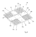
- FIG. 1 shows a schematic and perspective view of a cabinet 10 with partially open door 18.
- the cabinet 10 has a substantially cuboid cabinet body, which has a frame frame 12 inside.
- the door 18 is hinged on the front side right.
- a door lock 19 is attached approximately centrally with a manually operable opener.
- FIG. 2 shows in a schematic and perspective view of the cabinet body defining frame 12 of the in the FIG. 1 shown cabinet.
- the frame 12 is clamped cuboid.
- the door frame of the control cabinet 10 is formed by the front lower horizontal frame profile 12h, the two front vertical frame profiles 12i and 12l extending vertically upwardly therefrom, and the front upper horizontal frame profile 12d on the upper side.
- the rear frame of the cabinet 10 is formed by the rear lower horizontal frame profile 12f, the two extending vertically upwards thereto rear vertical frame profiles 12k and 12j and top side bounded by the rear upper horizontal frame profile 12b.
- the front door frame and rear frame are connected on the left side of the door frame by the lower left frame profile 12e and the left upper frame profile 12a and right side by the right lower frame profile 12g and the right upper frame profile 12c.
- the respective adjacent frame profiles are perpendicular to each other and are each connected by corner connectors 13 firmly together.
- the frame profiles 12a-l can be made of metal, for example aluminum or steel, or of plastic.
- FIG. 3 shows in a schematic and perspective exploded view in the FIG. 1 shown control cabinet.
- the cabinet 10 has the in the FIG. 2 shown frame frame 12, on which the following plate-shaped covers are mounted: the front side, the door 18 is hinged right to the front right vertical frame profile 12l. Laterally to the left of the door 18 is a left side wall 14a and to the right of the door 18, a right side wall 14b is attached to the frame 12. On the rear side, a rear wall 16 is attached to the rear frame of the frame 12. The top of the cabinet is closed by the lid member 30 which is attached to the upper horizontal frame profiles 12a-d.
- a base part 40 On the underside, a base part 40, with which the control cabinet 10 is on the floor, attached to the frame 12.
- the side walls 14a and 14b, the rear wall 16, the cover part 30 and the base part 40 are attached to the frame by screw connectors (not shown).
- FIG. 4 shows in a schematic and perspective view, the left side wall 14a of the in the FIGS. 1 and 3 shown cabinet.
- the right side wall 14b and the rear wall 16 of the cabinet 10 are equal to the left side wall 14a built.
- the door 18 may be constructed the same as the left side wall 14a.
- the left side wall 14a is substantially formed as a rectangular, plate-shaped cover, which consists of plastic and two plastic layers 20a and 20b, which are interconnected.
- the in the view of FIG. 4 Facing away from the viewer outer plastic layer 20a forms a flat outer side, which has an inwardly bent, circumferential edge 21 at its peripheral edges. The edge 21 serves to stiffen.
- a second, inner plastic layer 20b is inserted and firmly pressed to the outer plastic layer 20a.
- the inner plastic layer 20b opposite the outer plastic layer 20a forms a in the FIG. 4 perpendicularly from the bottom towards the top of the cabinet 10 in the middle between the two long sides of the left side wall 14a extending air duct 22.
- the air duct 22 is formed between the two plastic layers 20a and 20b and faces the applied to the outer plastic layer 20a inner plastic layer 20b as far as the circumferential edge 21st
- the inner plastic layer 20b has in the two formed by the air duct 22, on each of three sides by the peripheral edge 21 and on each side by the air duct 22 bounded areas 24a and 24b, a plurality of small, circular openings / rivets 26. At the in the view of FIG. 4 facing away from the viewer side of the inner plastic layer 20b, the openings 26 are covered by the outer plastic layer 20a.
- This hole grid / Nietraster serves for a stiffening. By providing the apertures 26, on the other hand, a weight saving is achieved.
- the air duct 22 has to the interior 11 of the cabinet 10 toward a plurality of equally spaced apart openings 28 of the same shape and size.
- the apertures connect the interior 11 of the control cabinet 10 with the interior of the air duct 22.
- the apertures 28 may be spaced apart at different distances.
- the breakthroughs 28 may differ in shape and size from each other.
- only a single breakthrough 28 may be provided in the air duct 22 or existing openings may be completely or partially covered by suitable (not shown) cover.
- the air duct 22 has an upwardly directed, slot-shaped flow opening 36, which is formed in the peripheral edge 21.
- FIG. 5 shows in a schematic and perspective view of the lid part 30 of the in the FIGS. 1 and 3 shown cabinet.
- the cover part 30 is attached to the upper side of the frame 12 adjacent to the laterally attached to the frame 12 side walls 14a and 14b and the rear wall 16.
- the lid member 30 is substantially formed as a square, plate-shaped cover, which consists of plastic and two plastic layers 20a and 20b, which are interconnected.
- the in the view of FIG. 5 Facing away from the viewer outer plastic layer 20a forms a flat outer side, which has an inwardly bent, circumferential edge 21 at its peripheral edges.
- the edge 21 serves to stiffen.
- a second, inner plastic layer 20b is inserted and firmly pressed to the outer plastic layer 20a.
- the inner plastic layer 20b relative to the outer plastic layer 20a four air ducts 32a, 32b, 32c and 32d extending from the edge portion 21 is substantially star-shaped to an outwardly leading opening 34 in the center of the cover member 30 and end there in slot-shaped outflow openings 35.
- the air ducts 32a, 32b, 32c and 32d are formed between the two plastic layers 20a and 20b and protrude as far as the peripheral edge 21 against the inner plastic layer 20b applied to the outer plastic layer 20a.
- the inner plastic layer 20b has in the four formed by the air ducts 32a-d, on two sides by the peripheral edge 21 and on two sides by the air ducts 32a-d limited areas 37a-d, a plurality of small, circular openings 26 , At the in the view of FIG. 5 facing away from the viewer side of the inner plastic layer 20b, the openings 26 are covered by the outer plastic layer 20a.
- This hole / Nietraster serves for a stiffening.
- the air ducts 32 ad of the cover part 30 each have a connection opening 38 which are aligned in the direction of the associated flow openings 36 of the air ducts 22 of the side walls 14 a and 14 b and the rear wall 16 and in the assembled state of the cabinet 10 with the flow openings 36 are brought into contact.
- a (not shown) fan means is arranged, which a flow of (not shown) by electronic installations heated air from the interior 11 of the cabinet 10 through the air ducts 24 of the side walls 14 a and 14 b and the rear wall 16 and through the air ducts 32 ad of the cover member 30 generated to the outside.
- the fan device may have a radial fan, which deflects the air from the opening in the opening 34 of the cover part 30, the air ducts 32 a-d of the cover part 30 to the outside in a known manner.
- FIG. 6 shows a schematic and perspective view of a base part 40 of the in the FIGS. 1 and 3
- the base part 40 is how the representations of FIGS. 1 and 3 show, mounted on the underside of the frame 12 of the cabinet 10.
- the base part 40 has a plurality of outside leading into the interior 11 ventilation openings 42. Through the ventilation openings 42 flows to compensate for the through the air ducts 24 and 32 ad outwardly discharged heated indoor air new fresh air from the outside into the interior 11 after.
- the base part 40 of FIG. 6 is made of plastic, especially designed as a plastic press, but may alternatively be made of metal.
- FIG. 7 shows in a schematic and perspective view of the door in the FIGS. 1 and 3 shown cabinet.
- the door 18 is substantially formed as a rectangular, plate-shaped cover, which consists of plastic and two plastic layers 20a and 20b, which are interconnected.
- the in the view of FIG. 7 the viewer facing outer plastic layer 20a forms an outer side, which is provided with a plurality of raised structures 44 which serve the stiffening.
- a recessed lettering 46 is embossed in the lower region of the outer side in the outer plastic layers 20a.
- a colored mark 48 is still applied.
- the outer plastic layer 20a has at its peripheral edges on an inwardly bent, circumferential edge 21.
- the edge 21 serves to stiffen.
- a second, inner plastic layer 20b is inserted and firmly pressed to the outer plastic layer 20a.
- the door 18 in an alternative embodiment may be substantially similar to that shown in Figs FIG. 4 shown left side wall 14a to be constructed.
- the door 18 may also have an air duct 22 formed between the two plastic layers 20a and 20b with an upwardly directed flow opening 36 which in the closed state of the door 18 is in air flow contact with a connection opening 38 of one of the air ducts 32 ad of the cover part 30.
- door lock 19 is in the illustration of FIG. 7 omitted.
- the door according to the FIG. 7 can be hinged to the frame 12 on the right or left side.
Landscapes
- Engineering & Computer Science (AREA)
- Power Engineering (AREA)
- Patch Boards (AREA)
Applications Claiming Priority (1)
| Application Number | Priority Date | Filing Date | Title |
|---|---|---|---|
| DE102010000243A DE102010000243B4 (de) | 2010-01-28 | 2010-01-28 | Schaltschrank |
Publications (2)
| Publication Number | Publication Date |
|---|---|
| EP2355276A2 true EP2355276A2 (fr) | 2011-08-10 |
| EP2355276A3 EP2355276A3 (fr) | 2013-03-20 |
Family
ID=43722099
Family Applications (1)
| Application Number | Title | Priority Date | Filing Date |
|---|---|---|---|
| EP11152311A Withdrawn EP2355276A3 (fr) | 2010-01-28 | 2011-01-27 | Armoire électrique avec panneaux en plastique |
Country Status (2)
| Country | Link |
|---|---|
| EP (1) | EP2355276A3 (fr) |
| DE (1) | DE102010000243B4 (fr) |
Cited By (1)
| Publication number | Priority date | Publication date | Assignee | Title |
|---|---|---|---|---|
| CN104992856A (zh) * | 2015-05-26 | 2015-10-21 | 天津平高智能电气有限公司 | 操动机构及其框架组件 |
Families Citing this family (2)
| Publication number | Priority date | Publication date | Assignee | Title |
|---|---|---|---|---|
| CN112736694B (zh) * | 2021-01-18 | 2024-04-23 | 宁波共盛电气科技有限公司 | 一种便捷安装的高低压开关柜 |
| DE102023115997A1 (de) * | 2023-06-19 | 2024-12-19 | Martin Hess | Quaderförmiges Schutzgehäuse, insbesondere quaderförmiges Anlagen- und/oder Instrumentenschutzhaus |
Family Cites Families (5)
| Publication number | Priority date | Publication date | Assignee | Title |
|---|---|---|---|---|
| DE29609776U1 (de) * | 1996-06-01 | 1996-10-10 | Stewing Feinblechtechnik GmbH & Co. KG, 46282 Dorsten | Gehäusewand für das Gehäuse und/oder die Tür eines Schrankes, insbesondere Lan- oder Kabelverzweigerschrankes zur Aufnahme elektrischer und/oder elektronischer Baugruppen |
| DE20121414U1 (de) * | 2001-08-09 | 2002-09-05 | Hess, Martin, 85051 Ingolstadt | Schutzgehäuse, insbesondere Instrumentenschutzhaus |
| JP2004200594A (ja) * | 2002-12-20 | 2004-07-15 | Agilent Technol Inc | 排気構造を有するシステムラック |
| DE102005017770A1 (de) * | 2005-04-13 | 2006-10-26 | Siemens Ag | Schrank für die Unterbringung von elektrischen Komponenten |
| DE102006024682B4 (de) * | 2006-05-19 | 2008-12-04 | Adc Gmbh | Geräteschrank mit zwei Kühlkanälen und Anordnung mit dem Geräteschrank |
-
2010
- 2010-01-28 DE DE102010000243A patent/DE102010000243B4/de not_active Expired - Fee Related
-
2011
- 2011-01-27 EP EP11152311A patent/EP2355276A3/fr not_active Withdrawn
Non-Patent Citations (1)
| Title |
|---|
| None |
Cited By (1)
| Publication number | Priority date | Publication date | Assignee | Title |
|---|---|---|---|---|
| CN104992856A (zh) * | 2015-05-26 | 2015-10-21 | 天津平高智能电气有限公司 | 操动机构及其框架组件 |
Also Published As
| Publication number | Publication date |
|---|---|
| DE102010000243B4 (de) | 2011-11-03 |
| DE102010000243A1 (de) | 2011-08-18 |
| EP2355276A3 (fr) | 2013-03-20 |
Similar Documents
| Publication | Publication Date | Title |
|---|---|---|
| DE102014101405B4 (de) | Bodenbaugruppe für das Rahmengestell eines Schaltschranks | |
| EP2986090B1 (fr) | Boîtier avec une partie inférieure et une partie supérieure | |
| EP3103168B1 (fr) | Profilé de cadre pour une armoire électrique ou de distribution | |
| EP2487429A9 (fr) | Boîtier carré, notamment en forme de cube, pour la réception de composants d'une installation technique de climatisation et/ou d'air ambiant | |
| CH619283A5 (fr) | ||
| WO2004106679A1 (fr) | Porte coulissante | |
| EP3589811A1 (fr) | Meuble comprenant un élément composite en forme de panneau démontable pourvu d'une ferrure intégrée | |
| DE102008059464A1 (de) | Verbindungssystem und Verbindungsvorrichtung | |
| DE102010000243B4 (de) | Schaltschrank | |
| CH700901B1 (de) | Bausatz zum Herstellen einer Transportbox für ein Tier. | |
| DE102014119303B3 (de) | Gehäuseanordnung eines Reisekoffers | |
| DE102007046936A1 (de) | Zweiteiliges Türschließergehäuse | |
| EP3825506B1 (fr) | Coffre de volet roulant pourvu d'une joue | |
| DE69815857T2 (de) | Fahrzeugtür | |
| EP1529187B1 (fr) | Porte d'appareil frigorifique | |
| DE2755135C2 (fr) | ||
| EP1352456B1 (fr) | Boitier, utilise notamment pour encastrer des composants electriques et electroniques | |
| DE9301542U1 (de) | Lüftergehäuse zur Anordnung in einer Durchlaßöffnung | |
| EP1511141B1 (fr) | Canalisation pour câblage et/ou montage d'appareillage | |
| EP1223648B1 (fr) | Porte comportant des moyens d'étanchéité pour la fermeture d'un tableau ou d'une armoire de commutation | |
| EP2997862B1 (fr) | Ensemble de boîtes aux lettres avec boîtier en forme de caisson | |
| EP2645503B1 (fr) | Boîtier pour la réception d'un support de système pour l'installation électrique du bâtiment et la technique de communication | |
| EP0413125A2 (fr) | Volet roulant pour meubles | |
| DE202017106174U1 (de) | Möbelkorpus für ein stapelbares Möbel | |
| DE2302988C3 (de) | Schränk für elektrische und elektronische Einrichtungen |
Legal Events
| Date | Code | Title | Description |
|---|---|---|---|
| PUAI | Public reference made under article 153(3) epc to a published international application that has entered the european phase |
Free format text: ORIGINAL CODE: 0009012 |
|
| AK | Designated contracting states |
Kind code of ref document: A2 Designated state(s): AL AT BE BG CH CY CZ DE DK EE ES FI FR GB GR HR HU IE IS IT LI LT LU LV MC MK MT NL NO PL PT RO RS SE SI SK SM TR |
|
| AX | Request for extension of the european patent |
Extension state: BA ME |
|
| PUAL | Search report despatched |
Free format text: ORIGINAL CODE: 0009013 |
|
| AK | Designated contracting states |
Kind code of ref document: A3 Designated state(s): AL AT BE BG CH CY CZ DE DK EE ES FI FR GB GR HR HU IE IS IT LI LT LU LV MC MK MT NL NO PL PT RO RS SE SI SK SM TR |
|
| AX | Request for extension of the european patent |
Extension state: BA ME |
|
| RIC1 | Information provided on ipc code assigned before grant |
Ipc: H02B 1/30 20060101AFI20130214BHEP Ipc: H02B 1/56 20060101ALI20130214BHEP |
|
| STAA | Information on the status of an ep patent application or granted ep patent |
Free format text: STATUS: THE APPLICATION IS DEEMED TO BE WITHDRAWN |
|
| 18D | Application deemed to be withdrawn |
Effective date: 20130921 |